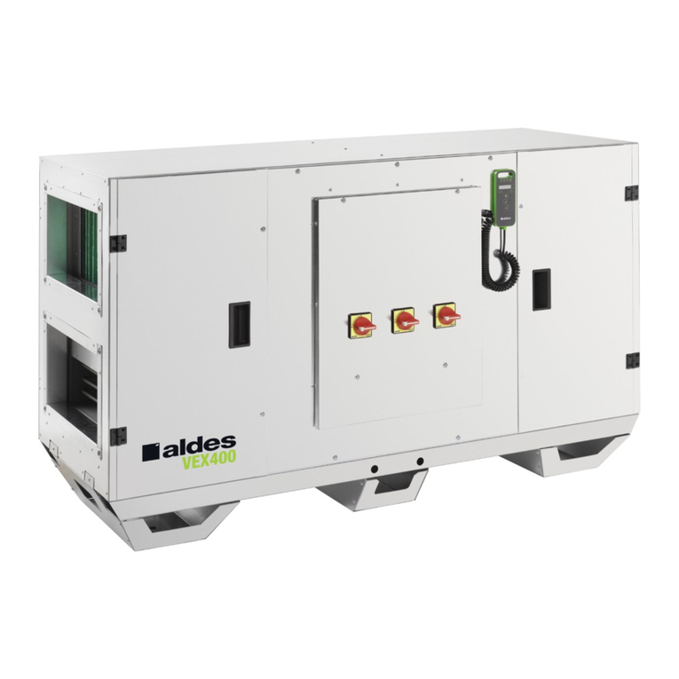
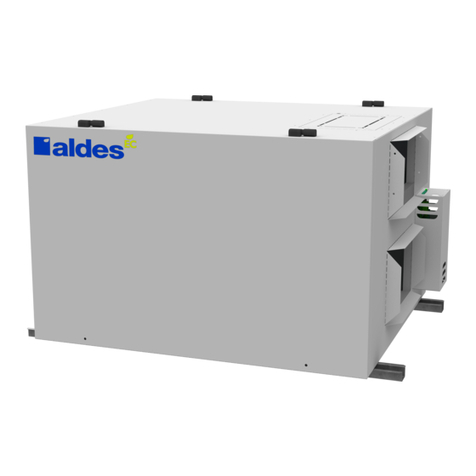
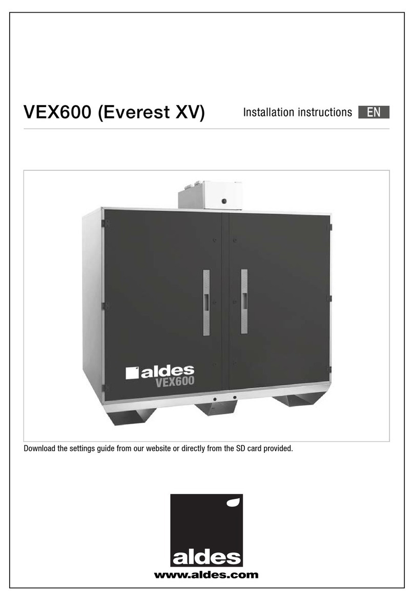
aldes VEX500 User manual

VEX500 (Everest XH) Installation instructions
EN
www.aldes.com

22
TABLE OF CONTENTS
1. RECOMMENDATIONS AND SAFETY SETPOINTS .................................................................................................4
1.1 Individuel protection ...........................................................................................................................................4
1.2 Installation and maintenance precautions .......................................................................................................4
2. INSTALLATION ..........................................................................................................................................................5
2.1 General information ............................................................................................................................................5
2.2 On-site transportation .......................................................................................................................................6
2.3 Parts included in the package ...........................................................................................................................6
2.3.1 Air input temperature probe..........................................................................................................................6
2.3.2 Documentation envelope ..............................................................................................................................6
2.4 Unit Assembly .....................................................................................................................................................7
2.4.1 General information.......................................................................................................................................7
2.4.2 Exterior version .............................................................................................................................................7
2.5 Direction of flow..................................................................................................................................................7
2.5.1 Right Version .................................................................................................................................................7
2.5.2 Left Version ...................................................................................................................................................7
2.6 Installing the temperature probe (air input sensor) .........................................................................................8
2.7 Installation options/accessories .......................................................................................................................8
2.7.1 Transformer component connection ............................................................................................................8
2.7.2 Canopy installation ......................................................................................................................................8
2.7.3 Installing air input/exhaust dampers.............................................................................................................9
2.7.4 Internal water cooling coil option ...............................................................................................................10
2.7.5 Constant pressure option ...........................................................................................................................11
2.7.6 LON option..................................................................................................................................................12
2.8 Hydraulic connection........................................................................................................................................12
2.8.1 Generalities on condensate connection .....................................................................................................12
2.8.2 Condensate exchanger connection............................................................................................................13
2.8.3 Condensate cooling coil connection ..........................................................................................................13
2.8.4 Internal cooling coil water collector connection .........................................................................................13
2.9 Connection to the mains power supply ..........................................................................................................14
2.9.1 Main Control – Power .................................................................................................................................14
2.9.2 Connections Electrical cables-power and control connections .................................................................15
2.9.3 Unit General power supply .........................................................................................................................16
2.9.4 De-icing battery pack power supply (optional) ...........................................................................................17
2.9.5 Connection electric heater battery power supply (optional) .......................................................................17
2.10 Filter maintenance ..........................................................................................................................................18
2.11 Configuring TCP/IP communication .............................................................................................................18
2.12 Remote control communication....................................................................................................................22
2.12.1 Using the remote control ..........................................................................................................................22
2.12.2 Menu access.............................................................................................................................................22

3
3. DIMENSIONS...........................................................................................................................................................23
3.1 Unit dimensions ...............................................................................................................................................23
3.1.1 VEX520-525-530.........................................................................................................................................23
3.1.2 VEX540-550 ................................................................................................................................................24
3.1.3 VEX560-570-580.........................................................................................................................................25
3.2 Exterior accessory dimensions .......................................................................................................................26
3.2.1 Roof.............................................................................................................................................................26
3.2.2 Rain canopies .............................................................................................................................................26
3.3 Transformer component drawings..................................................................................................................27
3.4 Diameter of internal water cooling coil collectors.........................................................................................28
4. CONTROL OPTIONS...............................................................................................................................................29

4
1. RECOMMENDATIONS AND SAFETY
SETPOINTS
Read the instructions in the manual carefully before starting to install the apparatus and keep the manual in good condition close to the apparatus
throughout its working life.
1.1 Individuel protection
• This apparatus can be used by children aged over aged 8 years and people with reduced physical, sensory or mental capabilities, or lacking in expe-
rience or know-how, (providing they) are properly monitored or are instructed in the safe use of the apparatus, and if any possible risks are clearly
understood.
• Children should not be allowed to play with the apparatus. User cleaning and maintenance must not be carried out by unsupervised children.
1.2 Installation and maintenance precautions
• Installation of an VEX unit can be dangerous due to moving or powered up components. This equipment should be installed, commissioned and
serviced by trained and qualied personnel, observing Standards and standard good practices.
• All servicing or maintenance operations requiring the access doors to be opened or one or more components to be removed must be carried out by
a qualied technician.
• All electrical connections to the equipment must carried out by a technician in accordance with requirements laid down in the NF C 15-100 Standard.
• In particular, a contact separation device with an opening of at least 3mm on each pole as well as a protection device with an appropriate rated
current should be installed in the inbuilt raceways (circuit breaker). Copper conductor sections are dened in sections 2.9.3, 2.9.4 and 2.9.5 of the
installation manual.
• The product must be powered down before any maintenance or cleaning operation.
• Make sure that the unit cannot be accidentally started up.
• To avoid any risk of accident, if a power cable is damaged it must be replaced by the technician who installed the product, or another qualied
technician.
• In the event that the motor overheats, its linear modulation will be reduced. When it exceeds its maximum internal temperature, the controller powers
down the motor and restarts it automatically after cooling. In the event of motor failure (motor integrated circuit failure signal, phase failure, motor stal-
led, shorted to ground or internal short circuit, intermediary or network reduced or excessive voltage, peak current fault) an alarm triggers apparatus
power down. Disconnect power supply (circuit breaker on the electrical panel), check that nothing is restricting unit operation (e.g. blocking, friction,
clogged wheel, abnormal noise...) and wait one hour before powering up again.
• If the problem persists, contact your installer or dealer.
• Use only manufacturer’s original parts.
• For units tted with an electric heating coil: in the event of multiple failures in electrical coil power control (at least two sensors failed) and in case of
overheating in the air input chamber (Ambient temperature > 80°C), an automatic rearming thermostat triggers electrical coil shutdown. In addition,
the electrical coil is tted with a manual reset thermostat which triggers at 120°C and is located in a sleeve between the resistors.
• To maintain the guarantee, no modications must be made to the apparatus.
• To ensure correct operation, the apparatus must be regularly maintained.

5
2. INSTALLATION
2.1 General information
Attention: the purpose of this document is to help in installing the unit. To attain complete installation compliance, please refer to the legislation in force
in the country of installation (e.g.: NF DTU 68-3 section 1.1.4).
• Access points•
A
ccess po
i
n
t
s
Access to controls
Switches, PLC’s of settings
Terminal block:
power supplies, ducts, signals etc.
unit power supply:
Single phase 230VAC to VEX520-VEX580
Three phase 400VAC+N+T for the others
Battery power supply:
Three phase 400VAC +N +T
Side panel:
2 opening frames
Side panel:
2 opening frames
Access door to
internal components
protected by a CHC
8mm key
The unit’s identication plate is located on the side panel.
The unit is supplied shrink-wrapped and protected with cardboard corners.
All accessories ordered with the unit are supplied unassembled. See section 2.7 for installing accessories.
Caution: do not pierce the surface between the two access doors and dividers because they integrate wiring systems!

6
2.2 On-site transportation
The unit is mounted on cross members. During transport by forklift, make sure forks are long enough so that all support struts are resting upon them.
Be careful not to damage the cross members when passing the forks under the unit (allow a minimum space of 350mm).
Support struts
Cross members
Fork separation 350mm min.
Handling using slings: Use the lifting bars placed inside the cross members. The bars' exural rigidity must be appropriate for the weight of the unit.
Place the sling loops around the lifting bars and place spacers above the unit so as not to damage the casing. See Diagram below.
Separators
Sings
Lifting bars
2.3 Parts included in the package
2.3.1 Air input temperature probe
A 3m long wire probe is provided, connected inside the lower connection box . It must be placed in the air input duct. The probe is equipped with a
metal support rod and a PG 9 cable gland, for installation see section 1.6.
2.3.2 Documentation envelope
All documents relating to using the unit are located behind the black door.
A SD card with a USB adapter containing the control and software conguration instructions are included in the documentation envelope.

7
2.4 Unit Assembly
2.4.1 General information
Assemble the unit’s cross members on a at, stable surface (at surface for condensates).
It is advisable to install an anti-vibration device between the Unit’s legs and the frame (e.g.: pads or mats) and between the pipe ttings and the duct
system (e.g.: exible cuff) to dampen any vibration generated by the motorised fans.
During unit installation and connection of ducts and electrical cables, make sure not to block the access points so that internal operational components
can be easily extracted, thus enabling electrical connection of the unit.
Space required for maintenance: to enable lter replacement, the 2 side doors must be able to open to a min. of 90°. The central black door must be
able to open to 180° for access to switches and controls.
Provide the space and height required for connecting a siphon to drain the condensates from the exchanger and cooling coil. See section 2.8.1.
700
700
2.4.2 Exterior version
The Everest units have IPX4 protection against water damage and pitting. units destined for exterior use are equipped with a weatherproof cover. To
ensure protection against rain entering into the unit’s internal compartments, it is necessary to install a rain canopy (sold as an option) on the air inputs
and exhausts, if they are not equipped with gutters. Alternatively, we recommend installing on the exterior version, insulation dampers on the air input
and exhaust orices.
Caution: Installation of the weatherproof cover must comply with DTU 43.1, Chap. 5.4. The overall size of the unit is greater with the weatherproof
cover and canopy! To install the canopy, see section 2.7.2, for dimensions see section 3.2.
2.5 Direction of flow
There are right and left air ow versions
2.5.1 Right Version
Fresh Air
Discharge
Exhaust
Air Supply
Fresh air ow to the right
2.5.2 Left Version
Fresh Air
Discharge
Exhaust
Air Supply
Fresh air ow to the left

88
2.6 Installing the temperature probe (air input sensor)
The air input temperature probe is delivered connected to the control terminal, terminals M16-M17. It must be located in the input duct. The probe must
pass through the connection terminal cable gland in order to ensure an IP54 seal.
Important: When the system includes heating or cooling coils, the probe must be placed after these heat components at a minimum distance of
1.5 metres – in order to ensure an even temperature on the section.
In terms of the duct, the probe, passes through a PG 9 cable gland, ensuring that the duct is sealed. It is maintained the entire length by a metal rod.
2.7 Installation options/accessories
The 2 side panels are equipped with M8 inserts at each corner of the opening frame in order to accommodate external accessories (transformer com-
ponents-dampers–Canopies).
Dampers Transformer
components
Rain canopy
2.7.1 Transformer component connection
Provide M8 screws and a EPDM foam self adhesive seal for installing transformer components on the unit. Glue the seal on the ange of the transformer
component to ensure that the structure is sealed. Then screw each transformer component into the inserts of the frame. To connect the circular ducts,
these must be tted with a rubber O-ring. See diameters per machine in Section 3.3.
Insulate ducts and shaped parts in accordance with the Standards and regulations in force.
2.7.2 Canopy installation
Canopies are supplied with M8 screws and a 5x10mm thick EPDM self adhesive seal.
Glue the seal onto the ange of the canopy to ensure that the structure is sealed.
Canopies help protect the unit from rainwater intrusion. They can be attached to the opening frame, on a damper or a rectangular sleeve.
Caution: To prevent the recirculation of exhausted air towards the the fresh air, allow a minimum distance of 4m between the air input and exhaust outlet
(See for DTU 68-3 section 1-1-4 residential buildings). For commercial buildings the RSDT requires that «the exhaust air extracted from the rooms must
be ejected at least eight metres from any window or fresh air input».
For canopy dimensions see section 3.2.2

99
2.7.3 Installing air input/exhaust dampers
Dampers are supplied with pre-wired actuators, an "RG" linking cable (whether there are one or two dampers), a junction box, self tapping screws, M8
screws and a 5x10mm thick EPDM self adhesive seal. Glue the seal onto the ange of the damper to ensure that the structure is sealed. Then screw
each damper in the inserts of the opening frame.
Connect the "RG" cable to the terminals RG1-RG2 terminals of the terminal block (see diagram below). For technical details on the terminals, see
section 2.9.2
Air input-exhaust damper connection
Labels Denition Comments
M17 Air input temperature
probe
Factory connected probe
to be placed in the air
input duct
M16
M12 CO2-0-10V Probe active if option has been
M4 GND Closed by default on the
terminal
M5 External unit stop
M4 GND NO
M3 High speed
M8 Fire Alarm contact Closed by default on the
terminal
M7 GND
RG1 ON/OFF- insulation
damper relay
NO (active if option has
been selected)
RG2
+24 24V AC actuator damper
GND
+24 24V AC CO2probe
GND
M36 unit Alarm return relay NO
M37
2 or 3 horizontal terminal jumper
2 vertical terminal jumper
Fast connector terminal-cable section 0.14
1.5mm 2-rigid or crimped contacts recommended.
Thread the cable through the junction box cable gland to ensure that the terminal is sealed. Thread the cable into the raceway, and through the grom-
met provided, and pull it out onto the side panel containing the insulation dampers. Attach the distribution box using self tapping screws between two
dampers, on the side panel. Thread the "RG" cable through the grommets of the distribution box.
The distribution box is used to connect the damper actuator cable to the "RG" linking cable. When there are 2 dampers (input and exhaust), the
2 actuator cables are connected in parallel. Installing cables (see diagram below) depending on your conguration-one or two dampers.
0
0
$,
*1'
0
5*
0
0
$,
$,
$5 $5
$5
$5
$5
$,
$,
$,
0
5*
*1'
0
0
0
$5
7YHU
0
0
0
*1'
0
0
0
0
0
0
5*
0
0
0
7MDX
0
0
0
0
0
0
0
0
0
0
0 0 0
0 0

1010
Distribution box Distribution box
3-way
connector
3-way
connector
3-way
connector
3-way
connector
RG Cable RG Cable
Towards terminal Towards terminal
Damper actuator cable Damper actuator cable
Towards damper Towards damper
Only one damper
Air input or exhaust
Two dampers in parallel
input and air exhaust
Black
Red
2.7.4 Internal water cooling coil option
The internal water cooling coils are supplied with a motorised 3 way and pre-wired valve, "BW" control cable and a temperature probe (for measuring
the temperature of the uid circulating in the cooling coil). The "BW" cable and temperature probe are connected on one side of the control terminal.
On the other side, they are located in the raceway, ready to be connected by the installer.
Hydraulic connection of the 3-way valve and the cooling coil collectors (see section 2.8.4). When the hydraulic connections are completed, carry out
the cable connections for the internal water cooling coil (see wiring diagram below).
Internal water cooling coil 3-way valve actuator connection drawing
Towards unit connection terminal block
BW Cable
Temperature
probe
on 3-way valve
Heat pump-ON/OFF
Connector
male 3 pin
Connector
female 3-pin 3-way valve actuator cable
Towards 3-way valve
Collar clips
Water circuit
cooling coil
Temperature
probe
Insulation
3 way
valve
Actuators
Water circuit
cooling coil
Cold pump-ON/OFF
Connect the male "BW" cable plug to the actuator female socket ("BW" cable wires 1, 2, 3).
If required, connect the 4 free wires of the of the "BW" cable enabling the cooling coil water circuit pump (hot or cold) to be switched on or off. In the event
of a reversible cooling coil, the two pumps can be switched on or off ("BW" cable wires 4 and 5. power supply to hot water pump; "BW" cable wires 6 and 7
Power supply to cold water pump). Wires 4-5 and 6-7 are non-voltage relays.
Caution: electrical connections of external appliances or those used in a damp environment must be watertight. It is recommended to protect the
connections between the actuator cable and the «BW» cable to a minimum of protection class of IPX5.
Locate the temperature probe on the 3-way valve of the internal cooling coil using a plastic snap fastener. To increase the accuracy of uid temperature
measurement, insulate the probe and 3-way valve.

1111
2.7.5 Constant pressure option
The kit consists of three RJ12 cables (labelled R8, R9 and R10) connected to the two PTH pressure sensors. Each sensor is linked to two metres of
transparent exible tube which is connected to 1 black pressure outlet. 4 self-tapping screws are provided in a plastic bag. The assembly is wired up
and constructed in the Factory and placed on the air input and output sidewall. Only the black pressure outlets are to be installed in ducts.
The upper PTH sensor should measure the pressure difference between the air outlet and the ambient air outside the unit. Its address arrow is set at
position “6”. The transparent hose is connected to the «-» sensor terminal (depressurised duct). Leave the «+» terminal exposed to fresh air. Drill a
10mm Ø hole in the outlet duct in order to insert the pressure outlet. Secure the pressure outlet, using two self-tapping screws. Remember to carefully
seal around each pressure outlet.
The lower PTH sensor should measure the pressure difference between the air inlet and the ambient air outside the unit. Its address arrow is set at
position “5”. The transparent hose is connected to the «+» sensor terminal (pressurised duct). Leave the «-» terminal exposed to fresh air. Drill a 10mm
Ø hole in the outlet duct in order to insert the pressure outlet. Secure the pressure outlet, using two self-tapping screws. Remember to carefully seal
around each pressure outlet.
DETAIL D
SCALE 1 : 5
Outlet sensor address arrow
is set at position 6.
Inlet sensor address arrow
is set at position 5.
Flexible Transparent hose slopes
towards the black pressure outlet
No low point!
Warning: the transparent tube must descend from the PTH pressure sensor to the duct’s black pressure inlet without allowing a low point beneath it.
Under certain conditions the air in the hose could condense. Water stagnation in the hose causes incorrect measurement leading to poor unit control!
Warning: for the best results, pressure should be measured where there is less risk of turbulence, that is to say, on a straight length of duct. The mini-
mum distance to be maintained from any turbulence is at least twice the diagonal of a rectangular cross section, and at least twice the diameter of a
circular section.

1212
2.8 Hydraulic connection
2.8.1 Generalities on condensate connection
Fit all condensate drains with a siphon (plate heat exchanger and cooling coil optional). Siphon height is calculated according to the under or excess
pressure in the apparatus, in order to enable the evacuation of condensates and prevent leakage of air from the unit.
Caution: the siphon must always be lled with water before the unit is started up. Risk of water evaporation during summer months. In order to have
greater water capacity, it is advisable to use a minimum of a Ø32mm diameter siphon (for VEX520-525-530 sizes, use a Ø20 to Ø32 reducing sleeve).
Caution, if risk of freezing in winter, be
prepared to insulate the siphon and the
drainage components if they are in an
unheated atmosphere.
Siphon calculation
"P" being the maximum pressure in Pa inside an operating unit, with a safety factor increase of 20
% (10 Pa=1mm of water column). Warning, be
prepared for more load reductions, (higher or lower pressure) with clogged lters!
Section of the unit with low pressure (at exchanger connection):
H1(mm) >= P/10
Hs >= Px0,075
Example: calculating a low pressure of 500 Pa, i.e. P=600 Pa with safety coefcient.
H1 >= 600/10 →H1 >= 60 mm et
Hs >= 600x0,075 →Hs >= 45mm

1313
In terms of exchanger condensates, the following, maximum total fan pressure can be safely used:
VEX520 à VEX540 (Everest XH 1000 à 2300) P max. = 800 Pa
VEX550 (Everest XH 3500) P max. = 1100 Pa
VEX560 à VEX580 (Everest XH 4500 à 7000) P max. = 1400 Pa
Section of the unit under pressure (at cooling coil connection):
H1 >= 35 mm
Hs(mm) >= P/10
Example: calculating a pressure of 500 Pa, i.e. P=600 Pa with safety coefcient. H1 >= 35 mm et Hs >= 600/10 →Hs >= 60 mm
In terms of internal cooling coil condensates, the aerolic blower system pressure can be used.
2.8.2 Condensate exchanger connection
Our condensate tanks are equipped with an aluminium diameter female tube.
Glue a corresponding male diameter PVC tube (for siphon connection) (see diagram below).
Ø20 mm inside dia.(female) Aluminium tube,
model VEX520 to VEX530
Ø32 mm inside dia. (female) Aluminium tube,
model VEX540 to VEX580
2.8.3 Condensate cooling coil connection
Our cooling coil condensate tanks are tted with a drain plug connected to a exible extensible tube opening at the front at the height of the raceway,
and under the cooling coil. The end of the exible PVC has an Ø32 male tting. Connect the exhaust outlet to a siphon (see section 2.8.1) by gluing
on an Ø32 female PVC cap.
2.8.4 Internal cooling coil water collector connection
For collector diameters and their location, see section 3.4
Collectors have a standard thread. Connect the cooling coil water collector’s water inputs and exhaust outlets.
The water input and outlet collectors are marked on the side panels of the unit (the water circuit is always counter to the air ow, for a cooling coil of at
least two rows). It is advisable to hold the collector with pair of pliers during connection in order to avoid damaging which can cause leakage.
Br sure to seal the collector connectors and provide either an expansion joint or exible connector in order to absorb any possible expansion or
contraction.
For nominal diameters of 3-way valves, see section 3.4
Caution: The cooling coils accept a maximum pressure of 8 bars.

1414
2.9 Connection to the mains power supply
Caution: electrical connections must be carried out by qualied electrician, wearing appropriate Personal Protective Equipment. Never work on the
unit when it is powered up. Electrical connection must be carried out in compliance with the NF C 15-100 Standard. Each power supply network must
be protected by an omnipolar circuit breaker with a contact opening distance of 3mm. For a single-phase power supply, use a Type A leakage current
differential circuit breaker. For a three-phase phase power supply, use a Type B leakage current differential circuit breaker. For these two types of power
supply, we recommend a differential sensitivity of 300mA. The recommended amperage for each circuit breaker, depending on size of unit, is dened
in sections 2.9.3, 2.9.4 and 2.9.5. Maximum recommended ambient temperature <45°C. Do not forget to connect the Earth.
2.9.1 Main Control – Power
The unit has an electric mains power circuit and a electric battery circuit. Each circuit has its own built-in "control - switch" in a compartment located
behind the black door at the top of the unit.
Electrical connections are carried out in the terminal block located in the lower part of the front of the unit (see diagram below).
Access to controls
Switches, control PLCs
• Access points
Terminal block:
power supplies, ducts, signals etc.
unit power supply:
Single phase 230VAC to VEX520-VEX580
Three phase 400VAC+N+T for the others
Battery power supply:
Three phase 400VAC +N + T
Control
SD card access - RJ45 - RJ12 cable
Control PLC
Master
Optional
Control PLC
Extension
Control terminal access
Control
terminal
Optional
Control terminal
Extension
Control Cables: Terminal-PLC
Power supply cables:
Switch-terminal
Junction box
Power
Switch access
Optional: Internal
battery power supply
switch (three-phase)
Optional : De-icing
battery power supply
switch (three-phase)
unit power supply switch (single
or three phase):
- Extraction fan/blower motor
-PLC
Power supply terminal access
Power-supply terminal
distribution
Transformer

1515
2.9.2 Connections Electrical cables-power and control connections
Unscrew the cruciform screw of the access door to the terminal block. Then unscrew the 2 cable gland support screws. Thread the cables through
cable glands in order to ensure they are sealed. After connecting the power and control cables, install a seal between the edges of the cable gland
support and the junction box.
Watertight seal on the edges of
the cable gland support
The rigid power cable conductors tted with connectors can be plugged directly into the spring terminals (no tools required). Conductors can be
released using a screwdriver and turning the orange latch located in front of the conductor’s insertion hole.
Flexible conductors without connectors must be inserted by pressing the latch to release the spring (see photo below).
By applying a very light force on the latch, you can check that the conductor is correctly inserted if the latch goes in without resistance by 1mm.
The jumpers plug into the holes in the terminal provided for this purpose (see photo below).
Conductor to terminal connection Jumper connection to terminal (for input/exhaust dampers)
3 terminal jumper 2 terminal jumper

1616
2.9.3 Unit General power supply
We recommend a 20A circuit breaker with a sensitivity differential of 300mA and a 1.5mm section cable for the general power supply.
Caution: three-phase power supply from the VEX560 (4500 XH) unit.
Unit power supply
Models Power supply Frequency Max. power
consumption (W)
Type of terminal
VEX520 1 ~ 230VAC +T 50Hz 1000 Snap-lock
connector terminal
- cable section
0.14 to 4 mm ² -
rigid conductor or
crimped contacts
recommended
VEX525 1 ~ 230VAC +T 50Hz 1000
VEX530 1 ~ 230VAC +T 50Hz 1000
VEX540 1 ~ 230VAC +T 50Hz 1420
VEX550 1 ~ 230VAC +T 50Hz 2720
VEX560 3 ~ 400VAC +N +T 50Hz 4420
VEX570 3 ~ 400VAC +N +T 50Hz 5020
VEX580 3 ~ 400VAC +N +T 50Hz 7220
Connection
power supply terminals
VEX520 - 525 - 530
VEX540 - 550
unit single phase 230V+T:
- 2 Motorised-Fans
extraction/blowing
- PLC
3(
/
1
$1
$/
$7
$1
$/
$7
Power supply terminal connection
VEX560 - 570 - 580
unit three phase power supply
3 x 400V +N +T :
- 2 Motorised-Fans
extraction/blowing
- PLC
3(
/
/
1
/
$1
$/
$/
$1
$7
$/
$/
$/
$7
$/

1717
2.9.4 De-icing battery pack power supply (optional)
VEX520 à VEX550 unit: We recommend a 20A circuit breaker with a sensitivity differential of
300mA and 4mm section cable for the general power supply.
VEX560 à VEX580 unit: We recommend a 40A circuit breaker with a sensitivity differential of
300mA and 6mm section cable for the general power supply.
Caution: three-phase power supply for all sizes.
Battery power supply
Models Power supply Frequency Max. power
consumption (W)
Type of terminal
VEX520 3 ~ 400VAC +N +T 50Hz 2620 Snap-lock
connector terminal
- cable section
0.5 to 10 mm² -
rigid conductor or
crimped contacts
recommended
VEX525 3 ~ 400VAC +N +T 50Hz 3740
VEX530 3 ~ 400VAC +N +T 50Hz 5610
VEX540 3 ~ 400VAC +N +T 50Hz 7480
VEX550 3 ~ 400VAC +N +T 50Hz 11220
VEX560 3 ~ 400VAC +N +T 50Hz 14960
VEX570 3 ~ 400VAC +N +T 50Hz 18700
VEX580 3 ~ 400VAC +N +T 50Hz 22440
Caution: Each coil is controlled by a solid state relay. The solid state relay may cause radio interference. The use of mains lters can be necessary in
the event the user has to meet CEM (EN/IEC 55011 Standard) requirements.
- Unit VEX520 à VEX550 (XH1000 to XH3500):220nF/760V/X1 lter
- Unit VEX560 à VEX580 (XH4500 to XH7000):330nF/760V/X1 lter
2.9.5 Connection electric heater battery power supply (optional)
VEX520 à VEX550 unit: We recommend a 20A circuit breaker with a sensitivity differential of
300mA and 4mm section cable for the general power supply.
VEX560 à VEX580 unit: We recommend a 40A circuit breaker with a sensitivity differential of
300mA and 6mm section cable for the general power supply.
Caution: three-phase power supply for all sizes.
Battery power supply
Models Power supply Frequency Max. power
consumption (W)
Type of terminal
VEX520 3 ~ 400VAC +N +T 50Hz 2620 Snap-lock
connector terminal
- cable section
0.5 to 10 mm² -
rigid conductor or
crimped contacts
recommended
VEX525 3 ~ 400VAC +N +T 50Hz 3740
VEX530 3 ~ 400VAC +N +T 50Hz 5610
VEX540 3 ~ 400VAC +N +T 50Hz 7480
VEX550 3 ~ 400VAC +N +T 50Hz 11220
VEX560 3 ~ 400VAC +N +T 50Hz 14960
VEX570 3 ~ 400VAC +N +T 50Hz 18700
VEX580 3 ~ 400VAC +N +T 50Hz 22440
Internal battery power supply
to terminal connection
Three phase power supply
internal electric battery
3 x 400V +N +T
N
L1
L2 L3
A9T
A9L3
A9L2
A9L1
A9N
De-icing battery power
supply to terminal
connection
De-icing battery three phase
power supply 3x400V+N+T
N
L1
L2 L3
A7T
A7L3
A7L2
A7L1
A7N

1818
Caution: Each coil is controlled by a solid state relay. The solid state relay may cause radio interference. The use of mains lters can be necessary in
the event the user has to meet CEM (EN/IEC 55011 Standard) requirements):
- Unit VEX520 to VEX550: 220nF/760V/X1 lter
- Unit VEX560 to VEX580: 330nF/760V/X1 lter
2.10 Filter maintenance
Caution: lter cleaning must be carried out by a qualied electrician and with the unit powered down (BT conductor powered up)
It is advisable to change the lters when the following nal load losses occur:
G4 lters: 250 Pa max.
F7 lters Drawing: 250 Pa ECO - 450 Pa max.
HE F7 lters: 250 Pa ECO - 450 Pa max.
Consult the parameters notice for resetting the load loss when changing lters in dynamic alarm.
2.11 Configuring TCP/IP communication
Connect the RJ45 cable to the TCP/IP plug of the Master PLC:
(1) Using the remote control, nd the IP control address, subnet mask, gateway and DNS
server as follows:
- User/Internet
- (To change the window: turn the control wheel. To change a value:
press the centre button and rotate the control wheel to the value required).
- Static/Dynamic IP:
• Set «Static» if direct PC/unit connection
• Set «Dynamic» if connection via a router
- Examples :
• IP address, e.g.: Default 172.20.20.3
• Default Subnet Mask, e.g.: 255.255.255.0
• Default Gateway, e.g.: 172.20.20.1
• DNS server required, e.g.: 172.20.20.3 (same IP address)
• Alternative DNS server: 0.0.0.0

19
2) On your PC, congure the IP address and DNS server address. Depending on the version of Windows, these are the 2 access paths:
a. With Windows XP
- Start/Connections/Show All Connections/Right click "local area connection"/properties:
- Internet Protocol/Properties:

20
b. With Windows 7
- Control Panel\Network and Internet\Network
and Sharing Centre
- Local network connection/Properties
- Click on Internet Protocol Version 4/Properties
This manual suits for next models
1
Table of contents
Other aldes Heating System manuals
Popular Heating System manuals by other brands

El-Björn
El-Björn TF 100HWI manual

CALEFFI
CALEFFI SATK50 Series quick start guide

Armstrong
Armstrong SH-2000 Installation and operation manual

Rinnai
Rinnai iHeat Operation manual

Fast
Fast RHE Series SELECTION, USE, INSTALLATION AND MAINTENANCE MANUAL

Oxygen
Oxygen X-Air C200 Installation and operation manual

Soler & Palau
Soler & Palau AKOR CONNECTION, INSTALLATION, MAINTENANCE

ComfortHeat
ComfortHeat ETN Series Operation manual

Jaga
Jaga DBEC.11 installation instructions

CALEFFI
CALEFFI SATK60 Series instruction sheet

Lochinvar
Lochinvar TISUN SCH-I-O Installation & operation manual

Apator Metra
Apator Metra E-ITN 10 Series Installation and service manual