Empty tank
Before the tank approaches maximum fill (as
seen through the sight-gauge (19), empty
the tank by connecting camlock fitting (5) to
an evacuation system. The length of suction
pipe (2) ensures that it clears the tank
bottom to prevent solids and sediments from
being sucked into and damaging the
evacuation pump.
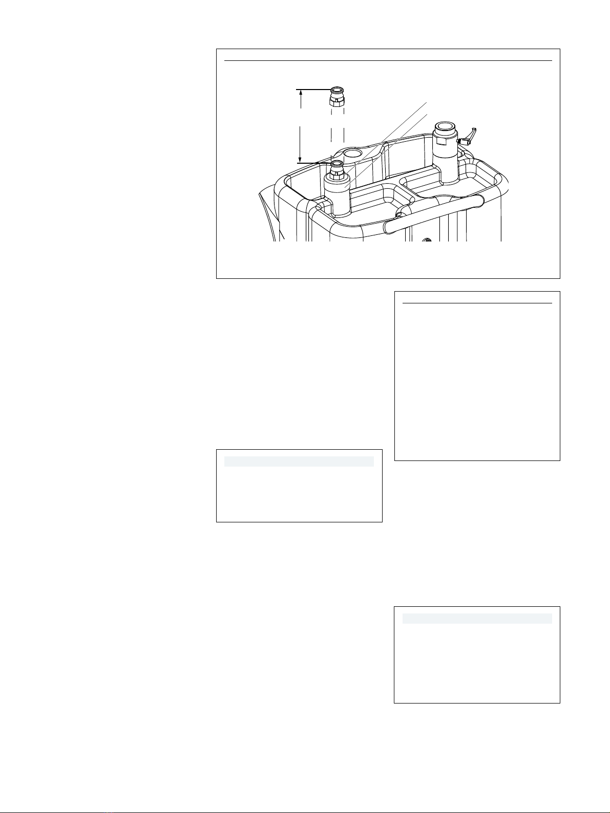
Sediments may build up high enough to
start clogging the suction pipe (2) before the
next scheduled tank purge. A stop-gap
feature has been designed into the suction
pipe (2) to enable oil evacuation to proceed
temporarily (→Fig. 1, page 4).
1 Apply wrench to camlock fitting (5) and
turn counter-clockwise. If necessary,
secure plug (4) with pipe wrench to hold
stationary.
2 Raise suction pipe (2) to maximum
height of 1 5/8in (41 mm).
3 Connect camlock fitting (5) to evacuation
system and complete emptying of tank.
4 Schedule tank purge as soon as possible
before tank fills up with sediments
and solids.
5 Upon completion of tank purge, turn
camlock fitting (5) clockwise as far down
as possible to reset suction tube (2)
height.
Purge tank
It may not be possible to safely purge the
tank of solids and sediments on the tank
bottom using the suction of an evacuation
system. We recommend the following steps
to completely purge the tank bottom of
sediments:
1 Evacuate tank of all fluids using
evacuation system.
2 Remove plug (22) on lower
connection (21).
3 Flush tank with water and normal
detergent until tank bottom is free of all
solids and sediments.
4 Reinstall plug (22) and check for leaks.
5 Turn camlock fitting (5) clockwise as far
down as possible to reset suction
tube (2) height.
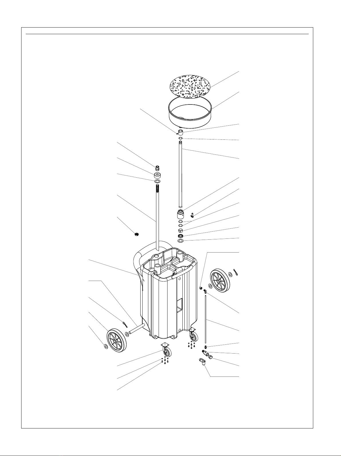
Parts list
Item Description Part number Quantity Kit number
1 Plastic cap 343341 1
2 Pipe, suction 1 393808-9
3 Seal, 2 in 2 393808-7, 393808-8,
393808-9
4 Plug, 2 in 1 393808-9
5 Connector, camlock 3/4in 343343 1 393808-9
6 Screw, SH cap 1 393808-6
7 Screen 343326 1
8 Funnel assembly 343327 1
9 O-ring 4100 1 393808-5, 393808-6
10 Bushing 1 393808-6
11 Drain tube 1 393808-7
12 Fitting, pipe holder 1 393808-7
13 Knob 343340 1 393808-7
14 O-ring 4131 2 393808-5, 393808-7,
393808-8
15 Lock-ring, split 1 393808-7, 393808-8
16 Ring-nut 1 393808-7
17 Adapter, 1/2in external × 1/4in internal 1 393808-4
18 Compression fitting (elbow) 1 393808-4
19 Sight gauge 1 393808-4
20 Compression fitting (straight) 1 393808-4
21 Lower connection 1 393808-10
22 Plug, 3/4in NPT 1 393808-10
23 Spigot, plastic - 3/4in NPT 343349 1) 1
24 Screw, cross head - M6 × 16 8 393808-1
25 Washer, lock 8 393808-1
26 Wheel, castor 2 393808-1
27 Washer, flat - 26 mm 4 393808-2, 393808-3
28 Wheel rubber 2 393808-3
29 Pin, cotter 2 393808-2, 393808-3
30 Axle 1 393808-2
31 Plastic tank 1
Part numbers left blank are not available separately.
1) Accessory - not part of drain assembly
5