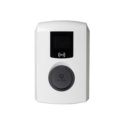
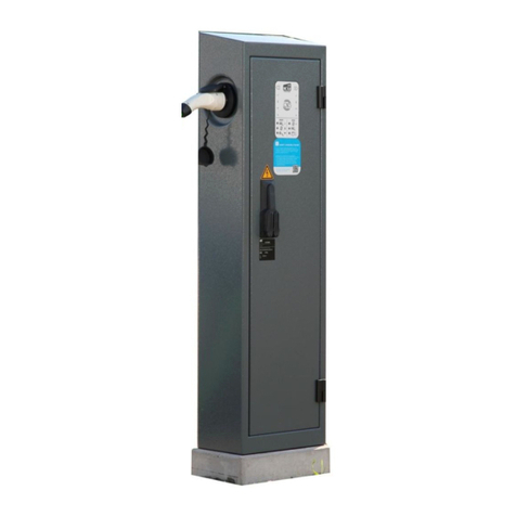
alfen Eve Single S-Line Installation and operating instructions

Suspend Charging mode
–
Installation guide
Addendum
Eve Single S-line
Eve Single Pro-line
Eve Double Pro-line

2
EVE SINGLE S-LINE
EVE SINGLE PRO-LINE
EVE DOUBLE PRO-LINE
with charging cable
with charging cable with socket
EVE SINGLE S-LINE
EVE SINGLE PRO-LINE
with socket

ENGLISH
3
Background information on
the Suspend Charging mode
–
Section 14a of the Energiewirtschaftsgesetz (German energy law) species the possibility
for consumers to use electricity at reduced standing charges if it complies with certain
conditions. The option only applies to customers who have a controllable device containing
an independent measuring module (for instance an EV charging station) connected to their
domestic energy connection.
The grid operator’s energy meter is equipped with a potential free contact. By connecting
the customer’s device to the grid operator’s energy meter via data cables, the grid operator
can send a signal to the charging station to temporarily abort the energy demand to
avoid an overload of the grid. During the shut-o time the customer will not be able to
charge, but will still be able to use other household equipment. Temporarily disabling the
possibility to charge is called the Suspend Charging mode.
This document describes the installation and conguration of the Suspend Charging mode
functionality.

4Suspend Charging mode installation guide |Version 1.0 |July 2019
ENGLISH
1 Safety and usage instructions 5
1.1 Purpose and intended audience 5
1.2 General safety 5
1.3 Copyright 5
1.4 Registered trademarks 5
1.5 Disclaimer of liability 5
1.6 Addendum to the manual and
installation guide 5
2 Functionality 6
2.1 Functionality 6
3 Assembly and connecting 7
3.1 Hardware setup 7
4 Installation 8
4.1 Requirements 8
4.2 Installationandcongurationprocedure 9
5 Conguration 10
5.1 Conguration 10
5.2 Enabling Suspend Charging mode using
a central management system 11
5.3 Enabling suspend Charging mode via
the Service installer 11
TABLE OF CONTENT

5
Suspend Charging mode installation guide |Version 1.0 |July 2019
ENGLISH
1. SAFETY AND USAGE INSTRUCTIONS
1.1 Purpose and intended audience
Make use of this addendum to the installation manual to
properly install and commission the charging station.
Installation, commissioning and maintenance of this
installationmayonlybeperformedbyaqualiedelectrician
(Alfen-ICUcertiedpartner).Itisessentialthatthe
qualiedtechnicianhas:
• Expertiseonallrelevantgeneralandspecicrules
regarding safety and incident prevention
• Comprehensive knowledge of applicable electrical
regulations.
• The ability to identify risks and avoid potential hazards.
• Received and read these installation and operation
instructions.
1.2 General safety
DANGER!
These safety instructions are important to ensure safe
operation. Failure to comply with them in accordance with
general electrical safety regulations could result in a risk of
electricalshock,reand/orlifethreateninginjury.
Using this product is expressly prohibited in the following
situations:
• Inthevicinityofexplosiveorhighlyammable
substances.
• If the product is located in or close to water.
• If the product or its individual components are damaged.
• Usage by children or individuals not able to properly
assess the risks associated with using this product.
Alfen ICU B.V. shall not be liable in any way, for any kind
of damage, and all warranties on both the product and
accessoriesshallbecomevoidwhere:
• There has been a failure to comply with the instructions
in this manual.
• Improper use.
• Installation and commissioning has been undertaken
byunqualiedpersons.
• The product or accessories have been expanded or
modiedwithoutourknowledge.
• Replacement parts have been used that are not
approved or manufactured by Alfen.
• The ambient temperature is below -25 °C or
above40°C.
• Situations have occurred that are beyond our control.
More extensive safety information is available in the
relevant sections of this document.
1.3 Copyright
Copyright©AlfenN.V.2019.Allrightsreserved.The
disclosure, duplication, distribution and editing of this
document, or utilization and communication of the content
are not permitted, unless authorized in writing. All rights,
including rights created by patent grant or registration of a
utility model or a design, are reserved.
1.4 Registered Trademarks
Eve ® is a registered trademarks of Alfen B.V. Therefore
unauthorized use of the trademark Eve or Eve Double Pro
Line® or Eve Double P.G. Line is illegal.
All other designations in this document can be trademarks
whose use by third parties for their own purposes can
infringe the rights of the owner.
1.5 Disclaimer of Liability
Thisdocumenthasbeensubjectedtorigoroustechnical
review before being published. It is revised at regular
intervals,andanymodicationsandamendmentsare
included in the subsequent issues. The content of this
document has been compiled for information purposes only.
Although Alfen ICU B.V. and Alfen B.V. have made best
eortstokeepthedocumentaspreciseandup-to-dateas
possible, Alfen ICU B.V. and Alfen B.V. shall not assume any
liability for defects and damage which result through use of
the information contained herein.
All obligations of Alfen ICU B.V. and Alfen B.V. are stated
in the relevant contractual agreements. Alfen ICU B.V. and
Alfen B.V. reserve the right to revise this document from
time to time.
1.6 Addendum to the manual and installation
guide
This installation guide is an addendum to the Alfen Eve
single(S-line,Pro-line)andEvedoubleusermanualsand
installationguides.Refertothespecicsectionsinthe
User manuals for relevant safety information.

6Suspend Charging mode installation guide |Version 1.0 |July 2019
ENGLISH
2.1 Functionality
Alfen has developed a solution to suspend a running
charging session on request of the grid operator.
Suspending the charging session is done in a controlled
way, according to the Mode 3 protocol.
The grid operators energy meter is equipped with a
potential free contact. The grid operator controls the
energymeterandcaneitheropenorclosethecontact(S1).
When the contact is closed, the charging station can charge
at full power. When the contact is open, the charging power
isreducedto0W.
The charging station makes sure a running transaction is
suspended according to the Mode 3 protocol. The screen
onthechargingstationwillshowamessagefortheuser:
‘Charging session halted by energy supplier’. In case the
charging station is not equipped with a screen, the blue
led will blink to indicate the power supply is halted by the
energysupplier.Duringtheshut-otimeitispossibleto
start a new charging session; the session, however, will be
paused immediately. As soon as the potential free contact
(S1)closesagain,thechargingstationwillcontinuethe
suspended charging session.
Image 1: Overview of the energy meter and charging station
2. FUNCTIONALITY
DANGER!
In this document the contact is considered to be closed
when charging is allowed. In practice it is possible that the
contact is open when charging is allowed. The installer is
responsible to assess the situation and act accordingly.
NOTICE!
This functionality is developed for all Eve (Single and
Double)chargingstationsandavailablefromsoftware
version 3.4.2 and higher.
S1

7
Suspend Charging mode installation guide |Version 1.0 |July 2019
ENGLISH
3. ASSEMBLY AND CONNECTING
RJ11
RJ12
RJ11
RJ12
RJ11
RJ12
3.1 Hardware setup
AnRJ11(orRJ12)datacableisusedtosendtheS1contactsignalstothechargingstation.Thedatacablesofthepotential
freecontactshouldbeconnectedtotheRJ11/RJ12connectoronthecontrollerboardofthechargingstation.
Image 2: Location RJ11/RJ12 connector CTL910 controller board
Image 3: Location RJ11/RJ12 connector on CTL920 controller board
Image 4: Location RJ11/RJ12 connector CTL910 controller board
EVE SINGLE S-LINE EVE SINGLE PRO-LINE
EVE DOUBLE PRO-LINE NOTICE!
Refer to the user manual and quick installation guide on
how to remove and install the front cover of the charging
station.
DANGER!
Refertothespecicsectionsintheusermanualandquick
installation guide manuals for relevant safety information.

8Suspend Charging mode installation guide |Version 1.0 |July 2019
ENGLISH
4. INSTALLATION
4.1 Requirements
Connecting the potential free contact with the charging station controller board should be done under the following strict
conditions:
1. No other connection is allowed. The two signal cables can only be connected to a potential free contact.
Image 5: Overview of the energy meter and charging station
2. The charging station should be the only device connected to the potential free contact
Image 6: Overview of the energy meter and charging station
3. NeveroeranexternalvoltageonthecontactsoftheRJ11connector.
S1
S1

9
Suspend Charging mode installation guide |Version 1.0 |July 2019
ENGLISH
4.2 Installation and conguration procedure
1. Verifythetypeofcontactintheenergymeterofthegridoperator(NOorNCcontact).
2. AdjustthechargingstationcongurationtoSuspendChargingmodebeforecontinuingtheinstallation.
Checkthecongurationchapterhowtocongurethechargingstation.
3. Dependingonthechosencongurationsetting,followthetestprocedureasshownbelow:
4. When the test is done successfully, the data cables can be attached to the potential free contact of the energy meter.
RJ11connector:Usesignalcable2and4toconnectwiththeenergymeterofthegridoperator.
RJ12connector:Usesignalcable3and5toconnectwiththeenergymeterofthegridoperator.
Image 7: RJ11 and RJ 12 connector
5. Start a charging session and check whether the behaviour of the charging station is as expected.
4. INSTALLATION
Station response Normally Closed (NC) contact Normally Open (NO) contact
Allow charging Suspend when closed Suspend when opened
Suspend charging Suspend when closed Suspend when opened
NOTICE!
Before installing the system read the requirements as described in the paragraph 'Requirements'.
NOTICE!
Selectingtherightsettingshouldbedoneaccordingtothecongurationofthecontactintheenergymeterofthegrid
operator.
Station response Test procedure
Suspend when closed Test procedure A
Step1:Shortcircuitpin2and4(RJ11)orpin3and5(RJ12).
Startachargingsession.Whenthecongurationissetright,thechargingstationwill
respondby(dependingonthetypeofchargingstation):
• Showing the message ‘Charging session halted by energy supplier’ on the screen
• Blinking the blue led when starting the charging process
Step2:Undotheshortcircuitingandstartachargingsession.Chargingispossible.
Suspend when opened Test procedure B
Step1:Shortcircuitpin2and4(RJ11)orpin3and5(RJ12).Startachargingsession.
Charging is possible.
Step2:Undotheshortcircuitingandstartachargingsession.Whenthecongurationis
setright,thechargingstationwillrespondby(dependingonthetypeofchargingstation):
• Showing the message ‘Charging session halted by energy supplier’ on the screen
• Blinking the blue led when starting the charging process

10 Suspend Charging mode installation guide |Version 1.0 |July 2019
ENGLISH
5.1 Conguration
CongurationoftheSuspendChargingmodecanbedoneviathebackoce(e.g.ICUConnect)orviatheServiceInstaller
application.
TocongurethestationforSuspendChargingMode,thefollowingcongurationkeyisavailable:
ThenameofthecongurationkeytosettheSuspendChargingmodedierspersoftwareversion:
Image 8: ICU Connect Conguration tab
5. CONFIGURATION
Conguration key Meaning Values
Direct external suspend
signal
Congureforwhich
purposetheRJ11/RJ12
port is used.
DSMR P1
Suspend when closed
Suspend when open
Conguration key Firmware version
Direct external signal 4.2.0andhigher
RJ11- Mode 3.4.1-3.4.3
(Not available) 3.4.0andearlier
NOTICE!
The Suspend Charging mode cannot be activated in combination with the Active Load Balancing functionality via P1
(SmartMeter).WhentheActiveLoadBalancingfunctionalityviaP1isenabledandthesettingforSuspendCharging
mode is activated, then this will be reverted to ‘DSMR P1’ when the charging station reboots. Therefore make sure P1 load
balancing is disabled before enabling the Suspend Charging mode. This can be done by deactivating the Active
LoadBalancingfunctionalityintheServiceInstallerapp(notpossibleviathebackoce).

11
Suspend Charging mode installation guide |Version 1.0 |July 2019
ENGLISH
5. CONFIGURATION
5.2 Enabling Suspend Charging mode using
a central management system
InthisparagraphthestepstocongureSuspendCharging
Mode are described using Alfen ICU Connect as an example.
Thecongurationparametersarealsomadeavailablein
third party central management systems. In case a third
party central management system is used to connect to
the stations, please refer to the third party’s description
aboutchangingcongurations.
1. Open ICU Connect and navigate to the charging
stations of interest
2. Go to tab Conguration
3. Press on Get Conguration
4. Gotoitem‘Directexternalsuspendsignal/RJ11-Mode’
andpressonEdit;thefollowingscreenwillappear:
Image 9: Edit conguration item screen
5. Adjustthevaluetooneofthefollowing:
6. Press Save
7. Sendthechangedcongurationbyclickingonthe
button
Image 10: Edit conguration item menu bar
8. Resetchargingstationtoeectuatethechanged
conguration
.
5.3 Enabling Suspend Charging mode via the
Service installer
The Suspend Charging mode is available in version 3.4.1
(andhigher)oftheServiceInstallerapplication.Ifapplicable
disable the Active Load Balancing functionality, before
settingthecongurationtoenableSuspendCharging
mode.
Value Function
DSMR Ready for P1 load balancing
Suspend when closed Suspends charging when closed
Suspend when open Suspends charging when open
Thiscanbedoneasfollows:
1. Go to the Load balancing tab
2. Go to Active Load Balancing
3. Deactivate the box at Active Load Balancing.
The functionality is now disabled.
4. Click on Save
Image 11: Service installer load balancing tab
ToenableSuspendchargingmode:
1. Go to the Power tab
2. Go to Installation
3. Select Allowed, suspend when closed or Allowed,
suspend when open
4. Click on Save.
5. Reboot the charging station by clicking the button
Image 12: Service installer Power settings tab
NOTICE!
Refer to the user manual and quick installation guide on
how to remove and install the front cover of the charging
station.
DANGER!
Refertothespecicsectionsintheusermanualandquick
installation guide manuals for relevant safety information.

Contact
–
Alfen ICU B.V.
Hefbrugweg 28
1332 AP Almere
The Netherlands
P.O. Box 1042
1300 BA Almere
The Netherlands
Tel. Sales Support: +31 (0)36 54 93 402
Tel. Service: +31 (0)36 54 93 401
Website: www.alfen.com/nl/oplaadpunten-ev
www.alfen.com/en/ev-charge-points
Contact
–
Alfen ICU B.V.
Hefbrugweg 28
1332 AP Almere
The Netherlands
P.O. box 1042
1300 BA Almere
The Netherlands
Tel. Sales Support: +31 (0)36 54 93 402
Tel. Service: +31 (0)36 54 93 401
Website: www.alfen.com/en/ev-charge-points
Other manuals for Eve Single S-Line
1
This manual suits for next models
2
Table of contents
Other alfen Automobile Accessories manuals