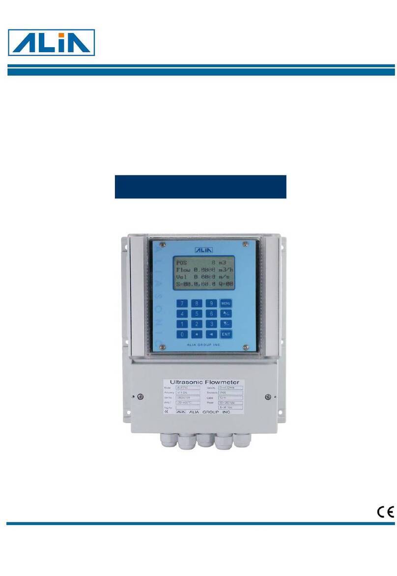
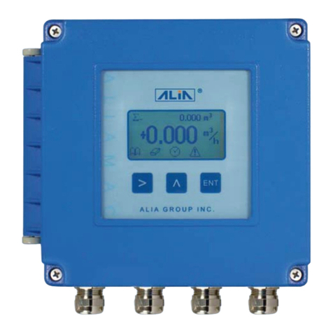
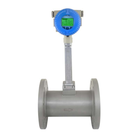
Alia AUF760 Series User manual

AUF760 Series Operation Manual OP760.1.1.7ENG
1
Transit-Time Ultrasonic Flowmeter
Model AUF760 Series
Operation Manual
Alia Group Inc. URL: http://www.alia-inc.com
TEL : +1 - 302 - 213 - 0106 FAX : +1 - 302 - 213 - 0107 OP760.1.1.7ENG
ALIASONIC
®

AUF760 Series Operation Manual OP760.1.1.7ENG
2
Index
1. Introduction- - - - - - - - - - - - - - - - - - - - - - - - - - - - - - - - - - - - - - - - - - - - - - - - - - - - - - - - - - - 4
1.1 Preface - - - - - - - - - - - - - - - - - - - - - - - - - - - - - - - - - - - - - - - - - - - - - - - - - - - - - - - - - - -4
1.2 Features - - - - - - - - - - - - - - - - - - - - - - - - - - - - - - - - - - - - - - - - - - - - - - - - - - - - - - - - - - 4
1.3 Principle of Measurement - - - - - - - - - - - - - - - - - - - - - - - - - - - - - - - - - - - - - - - - - - - - - 4
1.4 Applications- - - - - - - - - - - - - - - - - - - - - - - - - - - - - - - - - - - - - - - - - - - - - - - - - - - - - - - - 5
1.5 Packing List (standard) - - - - - - - - - - - - - - - - - - - - - - - - - - - - - - - - - - - - - - - - - - - - - - - 5
1.6 Figures and Wiring Diagram - - - - - - - - - - - - - - - - - - - - - - - - - - - - - - - - - - - - - - - - - - - 6
2. Starting Installation and Measurement - - - - - - - - - - - - - - - - - - - - - - - - - - - - - - - - - - - - - - 7
2.1 Inspection prior to Installation - - - - - - - - - - - - - - - - - - - - - - - - - - - - - - - - - - - - - - - - - - 7
2.2 Power supply- - - - - - - - - - - - - - - - - - - - - - - - - - - - - - - - - - - - - - - - - - - - - - - - - - - - - - - 7
2.3 Powering on - - - - - - - - - - - - - - - - - - - - - - - - - - - - - - - - - - - - - - - - - - - - - - - - - - - - - - - 7
2.4 Keypad Functions - - - - - - - - - - - - - - - - - - - - - - - - - - - - - - - - - - - - - - - - - - - - - - - - - - - 7
2.5 Keypad Operation- - - - - - - - - - - - - - - - - - - - - - - - - - - - - - - - - - - - - - - - - - - - - - - - - - - 7
2.6 Window Descriptions- - - - - - - - - - - - - - - - - - - - - - - - - - - - - - - - - - - - - - - - - - - - - - - - - 8
2.7 Pipe Parameter Entry Shortcuts - - - - - - - - - - - - - - - - - - - - - - - - - - - - - - - - - - - - - - - - 8
2.8 Transducer Wiring- - - - - - - - - - - - - - - - - - - - - - - - - - - - - - - - - - - - - - - - - - - - - - - - - - - 9
2.9 Installation - - - - - - - - - - - - - - - - - - - - - - - - - - - - - - - - - - - - - - - - - - - - - - - - - - - - - - - 9
2.10 Transducer spacing- - - - - - - - - - - - - - - - - - - - - - - - - - - - - - - - - - - - - - - - - - - - - - - - - 10
2.11 Transducer Mounting Methods - - - - - - - - - - - - - - - - - - - - - - - - - - - - - - - - - - - - - - - - 10
2.12 Z Method- - - - - - - - - - - - - - - - - - - - - - - - - - - - - - - - - - - - - - - - - - - - - - - - - - - - - - - - - 10
2.13 Transducer Mounting Inspection- - - - - - - - - - - - - - - - - - - - - - - - - - - - - - - - - - - - - - - 10
2.14 Signal Strength - - - - - - - - - - - - - - - - - - - - - - - - - - - - - - - - - - - - - - - - - - - - - - - - - - - - 10
2.15 Total Time and Delta Time - - - - - - - - - - - - - - - - - - - - - - - - - - - - - - - - - - - - - - - - - - - 10
2.16 Transit Time Ratio- - - - - - - - - - - - - - - - - - - - - - - - - - - - - - - - - - - - - - - - - - - - - - - - - - 10
2.17 Install Question - - - - - - - - - - - - - - - - - - - - - - - - - - - - - - - - - - - - - - - - - - - - - - - - - - - - 11
3. Operating Instructions- - - - - - - - - - - - - - - - - - - - - - - - - - - - - - - - - - - - - - - - - - - - - - - - - - - 12
3.1 System Normal Identification- - - - - - - - - - - - - - - - - - - - - - - - - - - - - - - - - - - - - - - - - - - 12
3.2 Measurement Units Options - - - - - - - - - - - - - - - - - - - - - - - - - - - - - - - - - - - - - - - - - - - 12
3.3 Flow Rate Units Options - - - - - - - - - - - - - - - - - - - - - - - - - - - - - - - - - - - - - - - - - - - - - - 12
3.4 Totalizer Units Options - - - - - - - - - - - - - - - - - - - - - - - - - - - - - - - - - - - - - - - - - - - - - - - 12
3.5 Totalizer Multiplier Options - - - - - - - - - - - - - - - - - - - - - - - - - - - - - - - - - - - - - - - - - - - - 12
3.6 On/off Net Totalizer- - - - - - - - - - - - - - - - - - - - - - - - - - - - - - - - - - - - - - - - - - - - - - - - - - 12
3.7 Totalizer Reset - - - - - - - - - - - - - - - - - - - - - - - - - - - - - - - - - - - - - - - - - - - - - - - - - - - - - 12
3.8 Factory Default Recovery - - - - - - - - - - - - - - - - - - - - - - - - - - - - - - - - - - - - - - - - - - - - - 12
3.9 Damping - - - - - - - - - - - - - - - - - - - - - - - - - - - - - - - - - - - - - - - - - - - - - - - - - - - - - - - - - - 13

AUF760 Series Operation Manual OP760.1.1.7ENG
3
3.10 Low Flow Cutoff- - - - - - - - - - - - - - - - - - - - - - - - - - - - - - - - - - - - - - - - - - - - - - - - - - - - 13
3.11 Zero Set Calibration - - - - - - - - - - - - - - - - - - - - - - - - - - - - - - - - - - - - - - - - - - - - - - - - 13
3.12 Scale Factor - - - - - - - - - - - - - - - - - - - - - - - - - - - - - - - - - - - - - - - - - - - - - - - - - - - - - - 13
3.13 System Lock (Unlock) - - - - - - - - - - - - - - - - - - - - - - - - - - - - - - - - - - - - - - - - - - - - - - - 13
3.14 4~20mA Current Loop Verification - - - - - - - - - - - - - - - - - - - - - - - - - - - - - - - - - - - - - 14
3.15 Frequency Output - - - - - - - - - - - - - - - - - - - - - - - - - - - - - - - - - - - - - - - - - - - - - - - - - - 14
3.16 Totalizer Pulse Output- - - - - - - - - - - - - - - - - - - - - - - - - - - - - - - - - - - - - - - - - - - - - - - 14
3.17 Alarm Programming - - - - - - - - - - - - - - - - - - - - - - - - - - - - - - - - - - - - - - - - - - - - - - - - 14
3.18 OCT Output- - - - - - - - - - - - - - - - - - - - - - - - - - - - - - - - - - - - - - - - - - - - - - - - - - - - - - - 15
3.19 Relay Output- - - - - - - - - - - - - - - - - - - - - - - - - - - - - - - - - - - - - - - - - - - - - - - - - - - - - - 15
3.20 Date and Time Settings- - - - - - - - - - - - - - - - - - - - - - - - - - - - - - - - - - - - - - - - - - - - - - 15
3.21 LCD Backlit Options - - - - - - - - - - - - - - - - - - - - - - - - - - - - - - - - - - - - - - - - - - - - - - - - 15
3.22 Daily, Monthly, Yearly Totalized Flow - - - - - - - - - - - - - - - - - - - - - - - - - - - - - - - - - - - 15
3.23 Automatic Flow Correction - - - - - - - - - - - - - - - - - - - - - - - - - - - - - - - - - - - - - - - - - - - 15
3.24 Working Timer- - - - - - - - - - - - - - - - - - - - - - - - - - - - - - - - - - - - - - - - - - - - - - - - - - - - - 15
3.25 Batch Controller- - - - - - - - - - - - - - - - - - - - - - - - - - - - - - - - - - - - - - - - - - - - - - - - - - - - 15
3.26 Analog Output Calibration- - - - - - - - - - - - - - - - - - - - - - - - - - - - - - - - - - - - - - - - - - - - 16
3.27 Software Version and ESN - - - - - - - - - - - - - - - - - - - - - - - - - - - - - - - - - - - - - - - - - - - 16
4. Windows Display Explanations- - - - - - - - - - - - - - - - - - - - - - - - - - - - - - - - - - - - - - - - - - - - 17
4.1 Windows Display Codes - - - - - - - - - - - - - - - - - - - - - - - - - - - - - - - - - - - - - - - - - - - - - - 17
4.2 Display explanation- - - - - - - - - - - - - - - - - - - - - - - - - - - - - - - - - - - - - - - - - - - - - - - - - - 18
5. Error Diagnoses - - - - - - - - - - - - - - - - - - - - - - - - - - - - - - - - - - - - - - - - - - - - - - - - - - - - - - - 30
6. Frequently Asked Questions and Answers- - - - - - - - - - - - - - - - - - - - - - - - - - - - - - - - - - - 32

AUF760 Series Operation Manual OP760.1.1.7ENG
4
1. Introduction
1.1 Preface
Welcome to the AUF760 series ultrasonic flow meter that has been manufactured with the newest technologies and is
equipped with more functions and advanced performance than our previous versions.
The AUF760 Series flow meter incorporates the latest ICs manufactured from the famous semiconductor manufacturers
like Philips, TI, Winbond, and Xilinx. The hardware features the ease of operation, high accuracy and outstanding
reliability, while the software provides a very user friendly interface and much more functions. It employs a patent
balanced lower voltage multi-pulse igniting circuit which increases the anti-interference ability magnificently so that the
flow meter will work properly even in demanding industrial environments such as those with power frequency transverter
working nearby.
Other outstanding features:
----the signal receiving circuits feature self-adapting performance so as to ensure that the user can easily operate the
instrument without any adjustment.
1.2 Features
With distinctive features such as high precision, high reliability and high capability, AUF-760 features other advantages:
*0.5% of linearity , 0.2% of repeatability
*Daily, monthly and yearly totalized flow(5 years)
*Self-Contained signal output, Including relay, open collector, 4~20 mA
*U.S., Britsh and Metric measurement units are available.
*Power on/off function(64 times as power sitched on/off)
*Low Power consumption, hith reliability, anti-jamming.
*Built-in data-logger
*Frequency/Pulse output
1.3 Principle of Measurement
When the ultrasonic signal is transmitted through the flowing liquid, there will be a difference between the upstream and
downstream transit time (travel time or time of flight), which is proportional to flow velocity, according to the formula
below.
as(1),(2)and(3)Formula,you can get Velocity:
D
B
A
Photo 1.3.1 ( Top View )
DOWNUP TT TDM
V×
Δ
×
×
=
θ
2sin
UPDOWN TTT −=Δ
θ
θ
sin
cos/
0VC DM
TDOWN −
×
=
θ
θ
sin
cos/
0VC DM
TUP +
×
=
……………………(1)
……………………(2)
…………………(4)
……………………(3)
Transducer
Transducer Spacing
Tup
Tdown
Pipeline

AUF760 Series Operation Manual OP760.1.1.7ENG
5
Remarks: M -- Transit time of the ultrasonic signal
D -- Pipe Inside Diamete
θ-- The angle between the ultrasonic signal and the flow
C
0-- No liquid movement the Fluid Sound Velocity
V -- Fluid Velocity
Tup -- Transit time in the forward direction
Tdown -- Transit time in the reverse direction
△T -- Tup –Tdown
1.4 Applications
1. Water, sewage (with low particle content) and
seawater 8. Marine operation and maintenance
2. Water supply and drainage water 9. Energy economy supervision and water conservation
management
3. Power plants (nuclear power plant, thermal and
hydropower plants) 10. Pulp and paper
4. Heat energy, boiler feed water and energy
management system 11. Pipeline leak detection
5. Metallurgy and mining applications 12. Regular inspection, tracking and collection
6. Petroleum and chemicals 13. Energy measuring and balance
7. Food, beverage and pharmaceutical 14. Network monitoring systems and energy/flow
computer management
1.5 Packing List (standard)
1. Transmitter (AUF760) 1 Set
2. Plug transducer (sensor) 1 Pair
3. Operation Manual 1 Copy

AUF760 Series Operation Manual OP760.1.1.7ENG
6
1.6 Figures and Wiring Diagram
Photo 1.6.2
Photo 1.6.1
GND
90 ~ 260
VAC
50/60HZ
RS-232
Communication
Contact
Output
Input
AI2
123456 78
3-30Vdc
Transistor
Output
91011 12
8~ 36
VDC
Red Black Red Black
1
2
3
4
5
68
79
10
11
12
F1
F2
F3
F4
4-20mA
Output
Input
AI1
F1 F2 F3 F4
Page 3
TOT 123456.78m3
FLOW 34.567m3/h
Vel 1.234m/s
S=86.7, 87.8 Q =87.9
123
456
789
0
MENU
ALIA GROUP INC .
Ultrasonic Flowmeter
Model Velocity
Accuracy Enclosure
Se r.No Cable
Amb.T Power
Ta g . No
AUF750
+/-1.0%
08050137
-20~+55 C
IP6 5
10m
0~+/-32m/s
90~260 Vac
8~36 Vdc
ALIASONIC
AIAI GROUP INC.
205 mm
235
mm
95 mm

AUF760 Series Operation Manual OP760.1.1.7ENG
7
2. Starting Installation and Measurement
2.1 Inspection prior to Installation
Inspection should be made before installing the AUF-760. Check to see if the spare parts are in accordance with the
packing list. Make sure that there is no potential damage to the enclosure due to a loose screw or loose wire, which
occurred during transportation. Any questions, please contact your representative as soon as possible.
2.2 Power supply
90-260Vac, 50/60 Hz or 8-36 VDC.
2.3 Powering on
As soon as AUF-760 flowmeter is switched on, the self-diagnosis program will start to run. If any error is detected, a
corresponding error code will display on the screen (Refer to Chapter of Error Diagnoses). After that, the system will run
automatically according to the last input parameters. If the installation is accomplished when system is switched on, gain
adjustment can be monitored in Window M01. After S1, S2, S3, S4 are displayed on the upper left corner of the screen,
the system will activate the normal measurement condition automatically. It is indicated by code “*R” on the upper left
corner of the screen. The system will default to the last window settings and automatically display then at every next
power on.
2.4 Keypad Functions
Follow these guidelines when using the AUF-760 flowmeter keypad (Refer to
Keypad Figure on the right-hand side of this page):
0 ~ 9 and . to input numbers.
to backspace or delete characters to the left.
▲/+and▼/- to return to the last menu or to open the next menu. Also acts as
“+” and “-” functions when entering numbers.
MENUto select a menu. Press this key first, input two menu numbersand then
enter the selected menu. For instance, to input a pipe outside diameter,
pressMENU 1 1 keys, where “11” is the window ID todisplay the
parameter for pipe outside diameter.
2.5 Keypad Operation
With all of the parameters entered, the instrument setup and measurement
displays are subdivided or consolidated into more than 100 independent
windows. The operator can input parameters, modify settings or display
measurement results by “visiting” a specific window. These windows are arranged by 2-digit serial numbers (including
“+” sign) from 00~99, then to +0, +1, etc. Each window serial number, or so-called window ID code, has a defined
meaning. For instance, Window M11 indicates the parameter input for pipe outside diameter, while Window F25
indicates the mounting distance between the transducers, etc.
The keypad shortcut to visit a specific window is to press the MENU key at any time, then input the 2-digit window ID
code. For instance, to input or check the pipe outside diameter, just press the ENT 1 1 keys for window ID code 11.
Another method to visit a particular window is to press ▲/+ , ▼/- and ENT keys to scroll the screen. For instance, if
the current window ID code is F66,press ▲/+ key to enter Window M65,press the ▲/+ button again to enter Window
M64; then, press the ▼/- key to back Window M65, and press the ▼/- key again to enter M66.
Example 1, To enter a pipe outside diameter of 1224, the procedure is as follows:
Press MENU 1 1 keys to enter Window M11 (the numerical value
displayed currently is a previous value). Now press ENT key. The
symbol “>” and the flashing cursor are displayed at the left end of the
second line on the Screen. The new value can be entered then…
1 2 2 4 ENT .
Example 2. If the pipe material is “Stainless Steel”, press keysMENU 1 4 to enter Window M14 first. Then press
ENT key to modify the options. Now, select the “1. Stainless Steel "option by pressing ▲/+ and ▼/- keys, and then
press ENT key to confirm the selection. It is possible to press the 1 key to
change the selection and wait until “1. Stainless Steel” is displayed on the
second line of the screen. Then press the ENT key to confirm.
M 11
PIPE OUTER
DIAME
210 mm
M 14
Pipe Material
5. pvc

AUF760 Series Operation Manual OP760.1.1.7ENG
8
Generally, press ENT key first if operator wants to enter “modify” condition.
If the “modify” is still not possible even after pressing the ENT key,
it means that system is locked by a password. To “Unlock” it,
select “Unlock” in Window M47 and enter the original password. The keypad will not respond if the
keypad is locked. It only can be unlocked by entering original password. Select keypad lock functions in
Window M47.
2.6 Window Descriptions
AUF760 has the unique feature of windows processing for all operations.
These windows are assigned as follows:
00~09 Flow Totalizer Display: to display flow rate, positive total, negative total, net total,
velocity, date & time, analog inputs for present flow, present operation and flow results
today, etc.
10~29 Initial Parameter Setup: to enter pipe outside diameter, pipe wall thickness, fluid type,
transducer type, transducer mounting and spacing, etc.
30~38 Flow Units Options: to select the flow unit, totalizer unit, measurement unit, turn totalizers
on/off and reset totalizes, etc.
40~49 Setup options: Scaling factor, zero adjustment, network IDN (M46, system lock (M47),
50~69 Calibration:Include printer function, RS-232 communication.4-20 mA output, flow Bacth controller,
date and time, etc.
70~79 Alarm output function.
80~89 Energy measureing setting.
90~94 Diagnoses: Signal strength and signal quality (M90), TOM/TOS*100 (M91), flow sound velocity (M92), total time
and delta time (M93), Reynolds number and factor (M94), etc.
+0~+7 Appendix: power on/off time, total working hours, on/off times and a single-accuracy
function calculator.
For further information, please refer to Chapter of Operating Instructions and Chapter of Windows Display Explanations.
2.7 Pipe Parameter Entry Shortcuts
The following parameters should be entered for normal measurement:
1. Pipe outside diameter
2. Pipe wall thickness
3. Pipe material
4. Liner material parameters (including thickness and sound velocity, if needed)
5. Fluid type
6. Transducer type (The transmitter is available for various transducer types)
7. Transducer mounting methods
In the order stated above, enter the above-mentioned parameters by the following keypad shortcuts:
1. Press MENU 1 1 keys to enter Window M11, and enter the pipe outside diameter, and then press the ENT key.
2. Press the ▼/- key to enter Window M12, pipe wall thickness, and press the ENT key.
3. Press the ▼/- key to enter Window M14, press the ENT key, move the ▲/+ or ▼/- key to select pipe material, and
press the ENT key.
4. Press the ▼/- key to enter Window M16, press the ENT key, move the ▲/+ or ▼/- key to select liner material, and
press the ENT key.
5. Press the ▼/- key to enter Window M20, press the ENT key, move the ▲/+ or ▼/- key to select fluid type, press the
ENT key.
6. Press the ▼/- key to enter Window M23, press the ENT key, move the ▲/+ or ▼/- key to select transducer type, and
press the ENT key.
7. Press the ▼/- key to enter Window M24, press the ENT key, move the ▲/+ or ▼/- key to select transducer-mounting
method, and press the ENT key.
8. Press the ▼/- key to enter Window M25, accurately install the transducer according to the displayed transducer
mounting spacing and the selected mounting method (Refer to Installing the Transducers in this chapter).
9. Press the MENU 0 1 keys to enter Window M01 to display measurement result.

AUF760 Series Operation Manual OP760.1.1.7ENG
9
2.8 Transducer Wiring
2.9 Installation
Photo 2.8.1 (Front view )
Transducer
Transducer Spacing
1
2
35
648
711
9
1210
Black
Red Black Red
10D 5D
ELBOW90
20D 10D
T-Tube
10D
Grove Value
5D
10D
Reducer
5D

AUF760 Series Operation Manual OP760.1.1.7ENG
10
2.10 Transducer spacing
Please enter window M25 for checking the installation space of insertion transducer
2.11 Transducer Mounting Methods
Use Z methods for transducer installation,Please enter Window M23 for checking the installation meathod.
2.12 Z Method (not commonly used)
Z method installation has less attenuation, because it utilizes a directly transmitted (rather than reflected) signal which
transverses the liquid only once.
2.13 Transducer Mounting Inspection
Check to see if the transducer is installed properly and if there is an accurate and strong enough ultrasonic
signal to ensure proper operation and high reliability of the transducer. It can be confirmed by checking the
detected signal strength, total transit time, delta time as well as transit time ratio.
The “mounting” condition directly influences the flow value accuracy and system long-time running reliability. In most
instances, only apply a wide bead of sonic coupling compound lengthwise on the face of the transducer and stick it to
the outside pipe wall to get good measurement results. However, the following inspections still need to be carried out in
order to ensure the high reliability of the measurement and long-term operation of the instrument.
2.14 Signal Strength
Signal strength (displayed in Window M90) indicates a detected strength of the signal both from upstream
and downstream directions. The relevant signal strength is indicated by numbers from 00.0~9.9.9 in the AUF-750 00.0
represents no signal detected while 99.9 represents maximum signal strength.
Normally, the stronger the signal strength detected, the longer the operation of the instrument reliably, as well as the
more stable the measurement value obtained.
Adjust the transducer to the best position and check to ensure that enough sonic coupling compound is applied
adequately during installation in order to obtain the maximum signal strength.
System normally requires signal strength over 60.0, which is detected from both upstream and downstream directions. If
the signal strength detected is too low, the transducer installation position and the transducer mounting spacing should
be re-adjusted and the pipe should be re-inspected.
2.15 Total Time and Delta Time
“Total Time and Delta Time ”, which displays in Window M93, indicates the condition of the installation.
The measurement calculations in the flowmeter are based upon these two parameters. Therefore, when “DeltaTime”
fluctuates widely, the flow and velocities fluctuate accordingly. This means that the signal quality
detected is too poor. It may be the resulted of poor pipe-installation conditions, inadequate transducer
installation or incorrect parameter input.
Generally, “Delta Time” fluctuation should be less than ±20%. Only when the pipe diameter is too small
or velocity is too low can the fluctuation be wider.
2.16 Transit Time Ratio
Transit Time Ratio indicates if the transducer mounting spacing is accurate. The normal transit time ratio
should be 100±3 if the installation is proper. Check it in Window M91.
If the transit time ratio is over 100±3, it is necessary to check
(1) if the parameters (pipe outside diameter,wall thickness, pipe material, liner, etc.) have been entered correctly,
(2) if the transducer mounting spacing is accordance with the display in Window M25,
(3) if the transducer is mounted at the pipe’s centerline onthe same diameter,
(4) if the scale is too thick or the pipe mounting is distorted in shape, etc.

AUF760 Series Operation Manual OP760.1.1.7ENG
11
2.17 Install Question
1. Pipe parameters entered must be accurate; otherwise the flowmeter will not work properly.
2. During the installation, apply enough coupling compounds in order to stick the transducer onto the pipe
wall. While checking the signal strength and Q value, move the transducer slowly around the mounting
site until the strongest signal and maximum Q value can be obtained. Make sure that the larger the pipe
diameter, the more the transducer should be moved. Check to be sure the mounting spacing is
accordance with the display in Window M25 and the transducer is mounted at the pipe’s centerline on
the same diameter. Pay special attention to those pipes that formed by steel rolls (pipe with seams), since
such pipe is always irregular. If the signal strength is always displayed as 00.0, that means there is no signal detected.
Thus, it is necessary to check that the parameters (including all the pipe parameters)
have been entered accurately. Check to be sure the transducer mounting method has been selected
properly, the pipe is not worn-out, and the liner is not too thick. Make sure there is there is indeed fluid
in the pipe or the transducer is not very close to a valve or elbow, and there are not too many air bubbles
in the fluid, etc. With the exception of these reasons, if there is still no signal detected, the measurement
site has to be changed.
3. Make sure that the flowmeter is able to run properly with high reliability. The stronger the signal
strength displayed, the higher the Q value reached. The longer the flowmeter runs accurately, the higher
the reliability of the flow rates displayed. If there is interference from ambient electromagnetic waves or
the signal detected is too poor, the flow value displayed is not reliable; consequently, the capability for
reliable operation is reduced.
4. After the installation is complete, power on the instrument and check the result accordingly.

AUF760 Series Operation Manual OP760.1.1.7ENG
12
3. Operating Instructions
3.1 System Normal Identification
Press the MENU 0 8 keys. If the letter “*R”displays on the screen, it indicates system normal. If the letter “E” is
read, it indicates that the current loop output is over ranged by 100%. This refers to the settings in Window M56. Enter a
larger value in Window M56, and the letter “E” will disappear. It can be ignored if no current loop output is used.
If the letter “Q” is read, it indicates that the frequency output is over ranged by 120%, and this refers to the settings in
Window M67.Incease the input value in Window M67, and the letter “Q” will disappear. It can be ignored if no frequency
output is used.
If the letter “H” is read, it indicates that the ultrasonic signal detected is poor. For more information, please
refer to Chapter of Error Diagnoses.
If the letter “G” is read, it indicates that system is adjusting the signal gain prior to the measurement. Also, it means
system normal. Only when the adjustment takes too long without stopping, can system be identified as abnormal.
Letter “I” indicates no signal is being detected. Check the transducer wiring connections are correct, the transducers are
installed firmly, etc.
Letter “J” indicates a hardware defect exists. Normally, such defect is temporary; it could be eliminated by system reboot
(power off and restart).
For further information, please refer to Chapter of Error Diagnoses.
3.2 Measurement Units Options
Window No.30 is available for British or Metric system options. Select 0 for Metric units, 1 for British units.
Press the MENU 3 0 ENT keys, and the symbol of “>” will be displayed on the bottom left line of the
screen. It indicates that the screen is ready for unit’s options selection. Press the ▼/- or ▲/+ key to select the desired
flow units, and then press the ENT key again to confirm.
3.3 Flow Rate Units Options
Window M31 is available for flow rate unit options. Press the MENU 3 1 keys to enter Window M31. Press the ENT
key. The symbol “>” is displayed on the bottom line of the screen; it indicates that the screen is ready for selection.
Press the ▲/+ or ▼/- key to select the desired flow rate units. Press the ENT key to enter the screen for time unit
options. Per the same selections as are in Section 3.3, move ▲/+ or ▼/- key to select the desired time unit; then press
the ENT key again to confirm.
3.4 Totalizer Units Options
Window M32 is available for totalizer unit options. The operation is as same as described in Section 3.2.
3.5 Totalizer Multiplier Options
The totalizer multiplier is used to expand the indication range of the totalizer.
It can be selected in Window M33.
3.6 On/off Net Totalizer
Window M34 is available to turn net totalizer on and off net. Window M35 is available to turn the positive
totalizer on and off, while Window M36 is for the negative totalizer.
Select “On” to activate the totalizer and “Off” to de-activate the totalizer.
3.7 Totalizer Reset
Window M 37 is available to select and reset the desired totalizer. Generally, it is unnecessary to activate
this function except during the initial installation.
3.8 Factory Default Recovery
Press the MENU 3 7 keys to enter Window M37, press the . ◄keys, and the factory default values
are recovered.

AUF760 Series Operation Manual OP760.1.1.7ENG
13
3.9 Damping
The damping function will stabilize the flow display. Essentially, it is a part of the signal filter. Enter a coefficient in
Window M40. Increasing the coefficient increases the stability. However, the measurement
displayed may be slightly delayed due to over damping. Logging too long may result in no response to
real-time fluctuation, especially when flow rate fluctuates wildly. Therefore, damping should be kept at a
minimum and increased just enough to reduce the fluctuation to an acceptable degree by 3 to 10 seconds.
This window is for data input. After entering the window, input the coefficient, then press the ENT key to
confirm.
3.10 Low Flow Cutoff
The data displayed in Window M41 is called the low flow cutoff value. If the flow rate falls below the low flow cutoff value,
the flow indication is driven to zero. This function can prevent the flowmeter from reading flow after a pump as shut
down but there is still liquid movement in the pipe, which will result in totalization error. Generally, 0.03m/s is
recommended to enter as the low flow cutoff point. The low flow cutoff value has no relation to the measurement results
once the velocity increases over the low flow cutoff value.
3.11 Zero Set Calibration
Once zero flow occurs, a zero point may indicated on each measuring instrument, i.e. as the measurement
value reaches zero flow, it is indicated as zero. It is necessary to establish the true zero flow condition and
program that set point into the instrument.
If the zero set point is not at true zero flow, a measurement difference may occur. The smaller the physical
measurement capacity is, the larger the measurement difference from the zero point will exist. Only when
zero point reduced to a definite degree, as compared with the physical measurement capacity, can the
measuring difference from zero point be ignored.
For an ultrasonic flowmeter, the measurement difference from zero point cannot be ignored at low flow. It
is necessary to perform a zero set calibration to improve low flow measurement accuracy.
Press the MENU 4 2 ensure that the fluid is definitely at a static state (true zero) and the flowmeter is working
properly. Press the ENT key and wait until the counter readings displayed in the lower right corner of the screen goes to
“00”; thus, the zero set is completed and the instrument indicates the results automatically through Window M01. Repeat
zero set calibration if it still needs to be minimized, i.e. the velocity reading is still high.
3.12 Scale Factor
Scale factor refers to the ratio between “actual value” and “reading value”. For instance, when the measurement is 2.00,
and it is indicated as 1.98 on the instrument, the scale factor reading is 2/1.98. This
means that the best scale factor constant is 1.
However, it is difficult to keep the scale factor as “1” on the instrument especially in batch control operations. The
difference is called “consistency”. High quality products always require high consistency. The scale factor default is “1”
for each instrument prior to shipment from the factory. The reason is that the scale factors in AUF-760 flowmeter are
only limited by two parameters, i.e. the crystal oscillation frequency and the transducer. It has no relation to any circuit
parameters.
During operation, there still exists possible difference in pipe parameters, etc. The “scale factor” may be
necessary when used on different pipes. Thus, scale factor calibration is specially designed for calibrating
the differences that result from application on different pipes. The scale factor entered must be one that
results from actual calibration.
3.13 System Lock (Unlock)
System lock is readable but uneditable to prevent operation error due to unauthorized tampering by
unauthorized personnel.
Press the MENU 4 7 ENT keys, move ▲/+ or ▼/- key to select “Lock”, press the ENT key, enter
a 1~4 numerically long password, and then press the ENT key to confirm.
Unlock using the selected password only. Press MENU 4 7 ENT, move ▲/+ or ▼/- to select
“Unlock”, press ENT, enter the correct password, then press ENT to confirm.
Keep the password in mind or recorded in a safe place or the instrument cannot be used.
§* Keyboard locked, avoid non-related person operation.
Locked way: Please get into the locked window, and please enter
MENU
4 8 ,then enter
ENT
,input the password,
it will returned back to the window .The keyboard will lose efficacy now.
Unlock way: Insert the passwork in the keyboard, the password won’t display .Only when you input the
correct password, then you could use it.

AUF760 Series Operation Manual OP760.1.1.7ENG
14
3.14 4~20mA Current Loop Verification
Possessing a current loop output exceeding an accuracy of 0.1%, the AUF-760 is programmable and configurable with
multiple output modules such as 4 ~20mA or 0~20mA. Select in Window M54. For details,please refer to Chapter of
Windows Display Explanations.
In Window M55, enter a 4mA flow value. Enter the 20mA flow value in Window M56. For instance, if the flow range in a
specific pipe is 0~1000 m3/h, enter 0 in Window M55 and 1000 in Window M56. If the flow ranges from -1000~0~2000
m3/h, configure the 20~4~20mA module by selecting Window M54 when flow direction is not an issue. Enter 1000 in
Window M55 and 2000 in Window M56. When flow direction is an issue, module 0~4~20mA is available. When the flow
direction displays as negative, the current output is in range of 0~4mA, whereas the 4~20mA is for the positive direction.
The output module options are displayed in Window M54. Enter “-1000” in Window M55 and 2000 in Window M56.
Calibrating and testing the current loop is performed in Window M57. Complete the steps as follows:
Press MENU 5 7 ENT, move ▲/+ or ▼/- to display “0mA”, “4mA”, “8mA”, “16mA”, “20mA” readings, connect an
ammeter to test the current loop output and calculate the difference. Calibrate it if the difference is within tolerance.
Check the present current loop output in Window M58 as it changes along with change in flow.
3.15 Frequency Output
The AUF-760 is provided with a frequency output transmitter function. The high or low frequency output displayed
indicates the high or low flow rate reading. The user can reset the frequency output as well as flow rate per his
requirements.
For instance: if a pipe flow range is 0~3000 m3/h, the relative frequency output required is 123~1000Hz, and the
configuration is as follows:
In Window M66 (low limit frequency output flow value), input 0;
In Window M67 (high limit frequency output flow value), input 3000;
In Window M65 (low limit frequency), input 123;
In Window M65 (high limit frequency), input 1000.
There is no output circuit specially assigned to frequency output. It only can be transmitted through OCT, i.e. select item
13 in Window M78 (item “OCT. FO”).
3.16 Totalizer Pulse Output
Each time the AUF-760 reaches a unit flow, it may generate a totalizer pulse output to a remote counter to configure the
unit flow.
The totalizer pulse output can be transmitted through OCT or a relay. So, it is necessary to configure OCT
and the relay accordingly.(Please refer to Window M78 and M79). For instance, if it is necessary to transmit the
positive totalizer pulse through a relay, and each pulse represents a flow of 0.1m3; the configuration is as follows:
1.In Window M32, select totalizer the flow unit “Cubic Meters(m3)”;
2.In Window M33, select the scale factor “2. x0.1”;
3.In Window M78, select “9. Positive totalizer pulse output”;
Note: Make sure to select a suitable totalizer pulse, since the output may be extended if it is too large. If it is
too small, the relay may activate too frequently and may probably shorten its life. Furthermore, if it operates
too fast, it may generate a pulse loss error. Therefore, a rate of 1~60/minute is recommended.
3.17 Alarm Programming
The AUF-760 has on off output alarm,
The on-off output alarm is generated through OCT or transmission to an external circuit by opening or
closing a relay. The on-off output signal is activated under the following conditions:
1. Signal not detected;
2. Poor signal detected;
3. The flowmeter is not ready for normal measurement;
4. The flow is in the reverse direction (back flow).
5. The analog outputs exceed span by 100%.
6. The frequency output exceeds span by 120%.
7. The flow rate exceeds the ranges configured (Configure the flow ranges using the software alarm system.
There are two software alarms: Alarm#1 and Alarm #2. The lower limit value for Alarm#1 is configured in Window M73,
and the upper limit value is configured in Window M74. As for Alarm#2, the lower limit value is in F75 and the upper one
is in Window M76).

AUF760 Series Operation Manual OP760.1.1.7ENG
15
Example 1: To program the relay output alarm, activated when flow rate exceeds 300~1000m3/h:
1. In Window M73, input 300;
2. In Window M74, input 1000;
3. In Window M79, select item 6: “6. Alarm #1 limit exceed”.
Example 2: To program OCT output alarm signal, activated when flow rate exceeds 100~500m3/h; relay
output alarm signal activated when flow rate exceeds 600~1000m3/h:
1. In Window M73, input 100;
2. In Window M74, input 500;
3. In Window M75, input 600;
4. In Window M76, input 1000;
5. In Window M78, select item 6: “6. Alarm #1 limit exceed”.
6. In Window M79, select item 6: “6. Alarm #1 limit exceed”.
3.18 OCT Output
The OCT output is a kind of isolated collector open circuit output with programmable open and close qualifications. The
user can program the open and close functions as Totalizer Pulse Output.
3.19 Relay Output
The relay output in the AUF-760 flowmeter is programmable. The user can program the open and close
functions as Totalizer Pulse Output. For details, please refer to Window M79.
3.20 Date and Time Settings
Generally, it is unnecessary to modify date time as the system is provided with a highly reliable perpetual
calendar chip. If necessary, key in the MENU 6 0 buttons to enter the window, then press ENT to see
‘>’ displayed on the bottom left line of the screen. It indicates that the screen is ready for the modification.
Press . to skip the numbers that do not need to be changed, and then press ENT again to confirm the
modification.
3.21 LCD Backlit Options
Adjust the backlighting in Window M70. Press MENU 7 0 , press ENT, and look for the ‘>’ displayed
on the bottom left line of the screen. It indicates that the screen is ready for modification. Press ▲/+ or ▼/-
to select “Always On”; it indicates that the backlighting will remain on always. If you select “Always Off”, it
indicates that the backlighting will remain off always. Select “Time=”, then enter the desired backlighting
time for “n” seconds; it indicates that after pressing the button, the backlighting will keep on for “n” seconds
then turn off automatically.
3.22 Daily, Monthly, Yearly Totalized Flow
In Window F09, the history file storage for the last 64 days can be reviewed.
Press MENU 8 2 , select item 0 for “Day” and it will display on the Screen
as shown on the right: Left upper corner: “00”-“63” indicates the serial numbers;
In the middle: “00-07-21” indicates the date;
Upper right corner: “-------” indicates the working condition.
If there is only “--------” displayed, it indicates the system was normal during that time period. If other
characters displayed, please refer to the “Error Code and Resolutions”. The following numerical value
3412.53 indicates the net totalized flow for a specific day.
To review the flow for a month, press MENU 8 2 , and select item 1 for “Month”.
To review the flow for a year, press MENU 8 2 , and select item 2 for “Year”.
3.23 Automatic Flow Correction
In Window M.2, select “4”, press ENT , select “1” ,the lost flow during an offline session will be automatically recovered
into the flow totalizer as soon as the next power on.
3.24 Working Timer
Window F.2 displays the total running hours since last reset.
3.25 Batch Controller
The batch controller is able to perform flow quantity control. The AUF-760 is able to take the high or low end of analog
input signals as an input, or through the keypad, to perform control functions. The output can be transmitted through
OCT or a relay.
When taking analog inputs as control signals, input an analog output which is over 2mA through the analog
input terminal to indicate the condition of “1”; current “0” indicates the condition of “0”.
In Window M78(OCT output )or M79(relay output), the OCT or relay output will generate output signals.
M 82
Date Totalizer
0. Day

AUF760 Series Operation Manual OP760.1.1.7ENG
16
3.26 Analog Output Calibration
Each flowmeter has been calibrated strictly before leaving factory. It is unnecessary to carry through this step except
when the current value (detected while calibrating the current loop) displayed in Window M62 is not identical with the
actual output current value.
The hardware detect window must be activated prior to calibration. The procedure is as follows:
Press MENU 6 2 ENT to calibrate the current loop 4mA output. Use an ammeter to measure the current loop
output current. At the same time, move ▲/+ or ▼/- to adjust the displayed numbers. Watch the ammeter until it reads
4.00. Stop at this point, the 4mA has been calibrated. Then, press ENT to calibrate the current loop 20mA output. The
method is as same as in 4mA calibration.
3.27 Software Version and ESN
We provide the AUF-760 with a unique electronic serial number to identify each flowmeter for the convenience of the
manufacturer and customers. The ESN, instrument types and versions are able to view in
Window M61.

AUF760 Series Operation Manual OP760.1.1.7ENG
17
4. Windows Display Explanations
4.1 Windows Display Codes
Item Flow Totalizer Display Item Setup Options Item Calorimetry
00 POS / NEG / NET Totalizer 46 Network I DN Diagnoses
01 POS / Flow Rate/Velocity 47 System Lock 90 Strength+Quality
02 NEG / Flow Rate/ Velocity 48 System Lock Code Entry 91 TOM/TOS*100
03 NET / Flow Rate/ Velocity 49 Communication Te 92 Fluid Sound Velocity
04 Date/ Time/ Flow Rate 93 Total Time and Delta
05 Instantaneous Caloric / Totalized
Caloric / Velocity
Setup Calibration 94 Reynolds Number
06 Analog Input AI1, AI2 50 Logger Option Appendix
Others 51 Logger Time *0 ON/OFF Time
07 System Error Codes 52 Printing To *1 Total Work Hours
08 Daily, Monthly, Yearly Totalized Flow 53 CL Calibration *2 Last Off Time
54 CL Mode Select *3 Last Flow Rate
Initial Parameter setup 55 CL(mA)4 Output V *4 ON/OFF Times
10 Pipe Outside Perimeter 56 CL 20mA Output V *5 Velocity Change
11 Pipe Outside Diameter 57 CL Checkup *6 Protocol Select
12 Pipe Wall Thickness 58 CL Current Output *7 Heat Capacity
13 Pipe Inside Diameter
14 Pipe Material 60 Date and Time
15 Pipe Sound Velocity 61 VER and ESN
16 Liner Material 62 RS-232C Setup
17 Liner Sound Velocity 63 AI1 Value Range
18 Liner Thickness 64 AI2 Value Range
19 Inside ABS thick 65 FO Frequency Range
20 Fluid Type 66 Low FO Flow Rate
21 Fluid Sound Velocity 67 High FO Flow Rate
22 Fluid Viscosity
23 Transducer Type Setup alarm
24 Transducer Mounting 70 LCD Backlit Option
25 Transducer Spacing 71 LCD Contrast
26 Parameters Setup 72 Working Timer
27 Current Section 73 Alarm #1 Low Value
28 Holding With Poor 74 Alarm #1 High Value
29 Empty Pipe Setup 75 Alarm #2 Low Value
Flow Units Options 76 Alarm #2 High Value
30 Measurement Unit 77 BUZZER Setup
31 Flow Rate Units 78 OCT Output Setup
32 Totalizer Units 79 Relay Output Set
33 Totalizer Multip 80 Flow Batch CTRL
34 NET Totalizer 81 FlowBatch Contro
35 POS Totalizer 82 Date Total izer
36 NEG Totalizer 83 Auto Amending
37 Totalizer Reset 84 Energy Units Sel
38 Manual Totalizer 85 Temperature Sele
39 Language 86 Spec Heat Select
40 Damping 87 Energy Totalizer ON/OFF
41 Low Flow Cutoff 88 Energy Multiplier
42 Set Zero 89 Reset Energy Totalizer
43 Reset Zero
44 Manual Zeropoint
45 Scale Factor

AUF760 Series Operation Manual OP760.1.1.7ENG
18
4.2 Display explanation
While reading this section, please compare it with the instrument in order to improve your understanding.
MENU
0
0
POS/NEG/NET/S,Q
Display POS Totalizer,NEG Totalizer ,NET Totalizer and S,Q Value.
If flowmeter installed correct, S & Q value need to higher then 60.
MENU
0
1
POS/Flow Rate/ Velocity /S,Q
Display POS Totalizer, Flow Rate, Velocity and S,Q Value.
If the pos totalizer has been turned off (refer to M35), the postotalizer
value displayed is the total prior to its turn off.
Select the positive totalizer units in Window M32.
MENU
0
2
NEG/Flow Rate/ Velocity /S,Q
Display NEG Totalizer, Flow Rate, Velocity and S,Q Value.
If the neg totalizer has been turned off (refer to M36), the postotalizer
value displayed is the total prior to its turn off.
Select the positive totalizer units in Window M32.
MENU
0
3
NET/Flow Rate/ Velocity /S,Q
Display NET Totalizer, Flow Rate, Velocity and S,Q Value.
If the net totalizer has been turned off (refer to M34), the postotalizer
value displayed is the total prior to its turn off.
Select the positive totalizer units in Window M32.
MENU
0
4
Date Time/Flow Rate
Display the current date time and flow rate.
The time setting method is found in Window M60.
MENU
0
5
Date Time/Flow Velocity
Display the current date time and Velocity.
MENU
0
6
Caloric/Totalized Caloric
Display Instantaneous Caloric and Totalized Caloric.
MENU
0
7
System Error Codes
Display the working condition and the system error codes.
Morethan one error code can occur at the same time.
The explanations of error codes and detailed resolution methods can be found in Chapter 5 – Defect Diagnoses.
MENU
0
8
NET Totalizer Today
Display NET Totalizer Today .
MENU
1
0
PIPE Outer Perimeter
Original factory rectified factor,not professional,please don’t change it.
POS +6 m3
Flow 0.0000 m3/h
Vel 0.0000 m/s
S=81.400,81.400Q=83.2
NEG -2 m3
Flow 0.0000 m3/h
Vel 0.0000 m/s
S=81.400,81.400Q=83.2
EFR 0.000GJ/h
E.T 0E0GJ
Vel 0.0000 m/s
S=81.400,81.400Q=83.2
AI1=00.0000
-12.490
AI2=00.0000
-12.490
POS + 6 m3
NEG -2 m3
NET + 4 m3
S=81.400,81.400Q=83.2
NET +4 m3
Flow 0.0000 m3/h
Vel 0.0000 m/s
S=81.400,81.400Q=83.2
Date 08-08-08
Time 08:08:08
Flow 0.0000 m3/h
S=81.400,81.400Q=83.2
Error Code
---------------------------
System Normal
S=81.400
,
81.400Q=83.2
M 08
Net FLOW Today
+231.22 m3
M 10
Pipe Outer Perim
659.735 mm

AUF760 Series Operation Manual OP760.1.1.7ENG
19
MENU
1
1
Pipe Outside Diameter
Original factory rectified factor,not professional,please don’t change it.
MENU
1
2
Pipe Wall Thickness
Original factory rectified factor,not professional,please don’t change it.
MENU
1
3
Pipe Inside Diameter
Original factory rectified factor,not professional,please don’t change it.
MENU
1
4
Pipe Material
Original factory rectified factor,not professional,please don’t change it.
MENU
1
6
Liner Material
Original factory rectified factor,not professional,please don’t change it.
MENU
2
0
Fluid Type
Select the fluid type. The following options are available:
0. WATER 8. OTHER
1. SEA WATER 9. DIESEL OIL
2. KEROSENE 10. CASTOR OIL
3. GASOLINE 11. PEANUT OIL
4. FUEL OIL 12. GASOLINE #66
5. CRUDE OIL 13. GASOLINE #80
6. PROPANE(-45C)14. ALCOHOL
7. BUTANE (0C)15. WATER(125C)
“OTHER"means you can go to keyin Ultrasonic speed for the fluid. In M21
MENU
2
3
Transducer Type
Select the Transducer type. The following options are available:
STANDARD - M 5. PLUG IN B45 10. STANDARD – M1
PLUG IN TYPE(C)6. STANDARD – L 11. STANDARD – S1
STANDARD – S 7. SCRA HUIZHONG 12. STANDARD – L1
USER TYPE 8. STANDARD - HS
STANDARD - B 9. STANDARD - HM
PLS choose the “5. PLUG IN B45 ”
MENU
2
4
Transducer Mounting
Four mounting methods are available:
0. V (V Method, sound wave bounces 2 times)
1. Z (Z Method, sound wave bounces once)
2. N (Small Pipe) (N Method, sound wave bounces 3 times.)
3. W (Tiny Pipe) (W Method, sound wave bounces 4times.)
PLS choose the “Z Method ”
M 11
Pipe Outer Diame
210 mm
M 12
Pipe Wall Thickn
3.0 mm
M 13
Pipe Inner Diame
204 mm
M 14
Pipe Material
5. PVC
M 16
Liner Material
0. None Liner
M 20
Fluid Tyoe
0. Water
M 23
Transducer Type
0. Standard - M
M 24
Transducer Mount
0. V

AUF760 Series Operation Manual OP760.1.1.7ENG
20
MENU
2
5
TRANSDUCER SPACING
Transducer Spacing (this value is CALCULATED by the AUF 760)
The operator must mount the transducer according to the transducer spacing displayed (be sure that the transducer
spacing must be measured precisely during installation). The system will display the data automatically after the pipe
parameter had been entered.
MENU
2
6
Parameter Setup and Save
Load and save the parameters. and save by three methods
0. Entry to Save
1. Entry to Load
2. To Browse
MENU
2
7
CURRENT AREA
Display the current area inside the pipe.
MENU
2
8
Holding when poor ultrasonic signal
When Flowmeter with poor signal, keep the flowrate data Condition.
MENU
2
9
Empty Pipe Setup
Setup a S value, when the value lower then this value, theFlowrate will go to 0.
MENU
3
0
Measurement Units Options
Select the measurement unit as follows:
0. Metric
1. English
Factory default is metric.
MENU
3
1
Flow Rate Units Options
Select the flow rate units and time units.
The following flow rate units are available:
0. CUBIC METERS
1. LITERS
2.(AMERICAN)GALLONS
3. IMPERIAL GALLONS
4. MILLION GALLONS
5. CUBIC FEET
6.(AMERICAN)BARRELS
7. IMPERIAL BARRELS
8. OIL BARRELS
The following time units are available:
/Day /Hour /Min /Sec
Factory default is Cubic Meters/hour.
MENU
3
2
Totalizer Units Options
Select the totalizer units. The available unit options are as same as
those found in Window M31.
The user can select units as their required. Factory default is Cubic Meters.
M 25
Transducer Spaci
72.8337 mm
M 26
Parameter Setup
ENTRY TO SAVE
M 27
Current Section
7389.81 mm2
M 28
Holding with Poo
YES
M 29
Empty Pipe Setup
0
M 30
Measurement Unit
0. Metirc
M 31
Flow Rate Units
m3/h
M 32
Totalizer Units
m3
Table of contents
Other Alia Measuring Instrument manuals
Popular Measuring Instrument manuals by other brands

TELEDYNE API
TELEDYNE API T108 Series Addendum to Operational Manual

Elma Instruments
Elma Instruments Elma BM251s manual

Barnett Engineering
Barnett Engineering ProTalk Cv3 Installation & operation manual

De Nora
De Nora 200 Series instruction manual

ACE INSTRUMENTS
ACE INSTRUMENTS ACE III Basic operating manual

GF
GF Signet 5090 manual