ATF2000 Operation Manual OP2000.1.2.3ENG
3
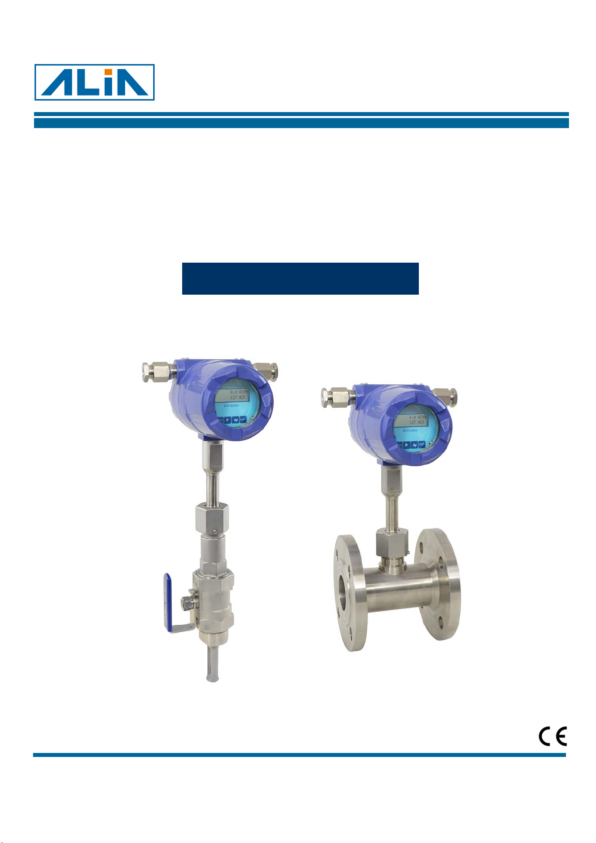
1. Introduction
ATF2000 Series thermal mass flow meter is designed on the basis of thermal dispersion. It adopts method of constant
differential temperature to measuring gas flow. It has the advantages of small size, high digitization, easy installation and
high accuracy.
The sensor consists of two platinum resistance temperature sensors. Using bridge circuit, one sensor is used as a
temperature sensor to monitor the actual process values while the other is used as a heater which is maintained at a
constant differential temperature above this by varying the power consumed by the sensor. It is possible to measure flow
at high temperature and high pressure.
ALIA ATF2000 thermal gas mass flowmeter has the following technical advantages:
●No need for temperature and pressure compensation. It can measure the mass flow rate or standard volume flow rate
of gas conveniently and accurately.
●Large range ratio. Gases with flow rates up to 120 m/s and down to 0.1 m/s can be measured. It can be used for gas
leak detection.
●Good anti-seismic performance and long service life. The sensor has no moving parts and pressure sensitive parts.
The measurement accuracy will not be affected by vibration.
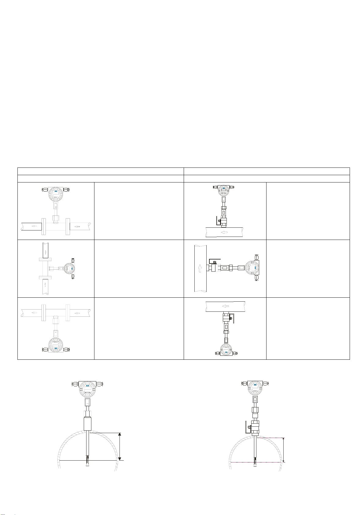
●Easy installation and maintenance. Non-stop production installation and maintenance is possible if site conditions
permit.
●Digital design. The whole instrument adopts a digital circuit which realizes accurate measurement and easy
maintenance.
2. Technical Parameters and Functions
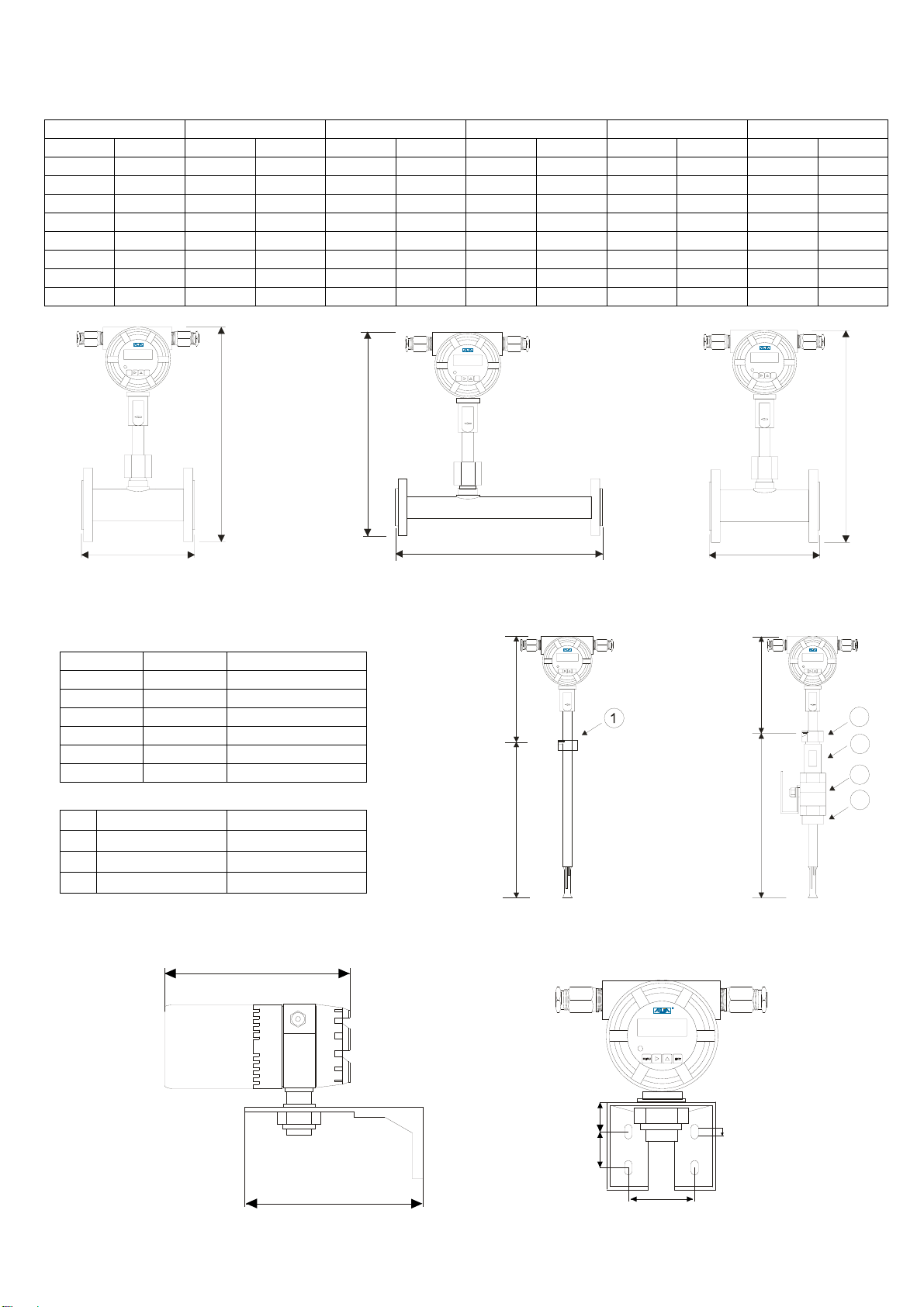
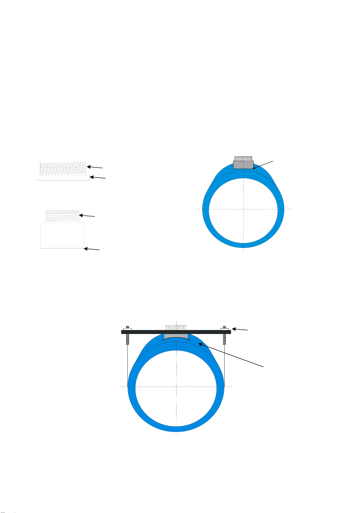
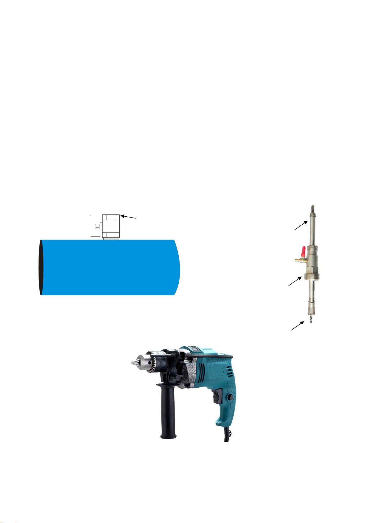
Insertion type Pipe-type
Measuring Medium Single component gas and multi-component gas
Pipe Size Circular pipe: DN80-7000 mm or
square pipe Circular pipe: DN10-1000 mm
Flow Rate 0.1-120 m/s
Accuracy +/-1%, of reading +/-0.5% FS
Working temperature Normal temperature type: -40-200 °C
High temperature type: -40-350 °C
Working Pressure Max. pressure: 63 kg/cm2(Please specify for special case)
Power Supply DC24V and AC90-260V Power ≤10W
Response Speed 1s
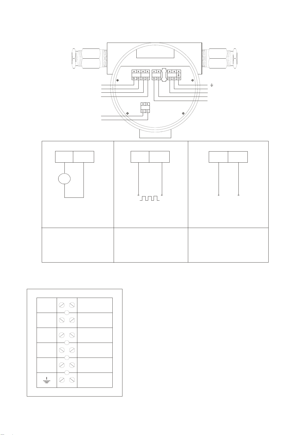
Current Output 4-20 mA (photoelectric isolation, up to 800 load), 2-channel 4-20 mA
photoelectric isolation (optional: 2-channel 4-20 mA).
Pulse Output
Cumulative pulse: Optical isolated OD output, max. current is 120 mA, optional,
0.1-5999.9 ms of Pulse width adjustable (0.1 ms of resolution), the Min. Pulse
interval time is 0.1-5999.9 ms (0.1 ms of resolution), the flow corresponding to
a single pulse is 0.001-59999. (Optional)
Communication
Output RS-485 (MODBUS-RTU) (photoelectric isolation)
Output
Signal
Alarm Output
No.2 circuit alarm limit can be DC30V/5A or AC250V/5A, which can be
programmable to be normally open or normally closed state, as well as other
alarm modes, such as flow and temperature limit alarm (optional function).
Pipe Material Metal or non-metallic
Display 16 * 2, English, flow rate, total flow, medium temperature, alarm status, total
running time, current date and time.
IP Grade Transmitter: IP67 Sensor: IP68
Explosion-proof Exd CTⅡ4