Alien Aircraft Corp K-308 User manual

Alien AircraftCorp.
403-AFlomichStreet
HollyHill, FL.32117
(386)676-0074
F4U-4Corsair KIT#K-308
WARRANTY
AlienAircraftCorp. guaranteesthiskitto befreefromdefectsin bothmaterialandworkmanship atthedateofpurchase.Thiswarranty doesnot
coverany componentpartsdamaged by useormodification. In no caseshallAlienAircraftCorp.s’liabilityexceed theoriginalcostofthepurchased
kit.Further,AlienAircraftCorp. reservestherightto changeormodify thiswarrantywithoutnotice.Thequality and flyability ofyourfinished
modeldependson howyou buildit;therefore,wecannotin any wayguaranteetheperformance ofyourcompleted model, and no representationsare
expressed orimpliedastotheperformanceorsafety ofyourcompletedmodel.
In thatAlienAircraftCorp.hasnocontroloverthefinalassembly ormaterialused forfinalassembly, no liabilityshallbeassumed noracceptedfor
any damageresulting fromtheusebytheuserofthefinaluser-assembled product. Bytheactofusing theuser-assembledproduct,theuseraccepts
allresulting liability. Ifthebuyerisnotprepared to accepttheliabilityassociatedwith theuseofthisproduct,thebuyerisadvised to returnthiskit
immediately innewand unusedconditiontotheplaceofpurchase.
WARNING!!!
Failuretofollowthesesafetyprecautionsmay resultin severeinjury toyourselfand others.
Usesafetyglasseswhen running themotor.Donotrun themotorin an areaofloosegravelorsand;thepropellermay throwsuch materialinyour
face oreyes. Keep yourface and body aswellasallspectatorsawayfromtheplaneofrotation ofthepropellerasyourun themotor.Keep these
itemsaway fromtheprop:looseclothing, shirtsleeves,ties, scarfs,long hairorlooseobjectssuch aspencilsorscrewdriversthatmayfalloutof
shirtorjacketpocketsinto theprop. AlwaysremovetheLiPo batteryfromtheplanebeforecharging.Alwaysuseachargerdesigned tochargeLiPo
batteriesforchargingtheLiPo flightbattery.NeverleavetheLiPo batteryunattended whilecharging. Ifthebattery becomesmorethanjustwarm,
discontinuecharging.
AssemblyInstructions
TM
©2012AlienAircraftCorp
DesignedbyTomHerr
NOTE: 3bladed prop isfordisplay
only.UseAPC9X3.8SFPropeller
while operating model.

Notesaboutthelasercutparts
1...Thefirstthingthatyouneedtodoistoidentifyand markthepartnumbersonthelasercutpartsusingthedrawingsonthefollowingpagesasaguide.
2...Itispossiblethatseveralofthelasercutpartsmaynotbecompletelycutthrough.Ifthisisthecaseyou canfreethepartfromthesheetquicklyusinganX-actoknife.
3...Theslightdiscolorationontheedgesofthelasercutpartsmayberemovedbylightlysandingtheedgeswith400 gritsandpaper.
KitContents:
Yourkitcontainsthefollowing parts.Pleasecheckyourkitforanymissingordamagedpartsbeforestartingconstruction.
WoodBag:
Qty.... ....Name. .... ............ .... .Description
1..... ....LC-308-01. ............ .... .1/16”X4”X24”LaserCutBalsa
1...... ....LC-308-02. ............ .... .1/16”X4”X24”LaserCutBalsa
1...... ....LC-308-03. ............ .... .1/16”X4”X24”LaserCutBalsa
1..... ....LC-308-04. ............ .... .3/32”X4”X24”LaserCutBalsa
1...... ....LC-308-05. ............ .... .3/32”X4”X24”LaserCutBalsa
1..... ....LC-308-06. ............ .... .3/32”X4”X24”LaserCutBalsa
1..... ....LC-308-07. ............ .... .1/8”X4”X24”LaserCutBalsa
1...... ....LC-308-08. ............ .... .1/8”X4”X24”LaserCutBalsa
1..... ....LC-308-09. ............ .... .1/8”X4”X24”LaserCutBalsa
1..... ....LC-308-10. ............ .... .1/8”X4”X24”LaserCutBalsa
1...... ....LC-308-11.. ............ .... .1/8”X4”X24”LaserCutBalsa
1..... ....LC-308-12. ............ .... .1/8”X4”X24”LaserCutBalsa
1..... ....LC-308-13. ............ .... .1/8”X4”X24”LaserCutBalsa
1...... ....LC-308-14. ............ .... .3mm X4”X24”” LaserCutPoplarPly
1...... ....LC-308-15. ............ .... .3mm X4”X24”” LaserCutPoplarPly
1..... ....LC-308-16. ............ .... .3/32”X4”X12”LaserCutBalsa
1..... ....LC-308-17. ............ .... .1/16”X3”X12”LaserCutBirchPly
1...... ....LC-308-18. ............ .... .1/16”X3”X12”LaserCutBirchPly
1...... ....LC-308-19. ............ .... .1/32”X3”X12”LaserCutBirchPly
3..... ....WingSheet. ............ .... .1/16”X3”X12”Balsa
1...... ....K-308PLAN A
1...... ....K-308PLAN B
8...... ....MainWingSpars......... .... .3/32”X1/4”X12”Balsa
4...... ....WingLeadingEdges...... .... .1/4”sq. X12”Balsa
14 ..... ....FuselageStringers........ .... .1/8”sq. X36”Balsa
12 ..... ....StringerSpars........... .... .3/32”sq.X24”Balsa
5...... ....TrailingEdge........... .... .1/16”x3/4”x18”Balsa
HardwareBag
Qty.... ....Name. .... ............ .... .Description
4...... ....BlindNuts.. ............ .... .4-40BlindNuts
1..... ....ElevatorJoiner.......... .... .1/8”x3”BirchDowel
4...... ....ControlHorn............ .... .ControlHorns
4...... ....C/AHinges. ............ .... .Hinges
18 ..... ....AileronServo &L/GScrews.... .#2X1/2”SheetMetalScrews
1...... ....TailwheelReinforcement... .... .1”X11/2”Nylon Tape
1...... ....Tail WheelWire......... .... .1/16”x8”Tail WheelWire
2...... ....LandingGearBlocks...... .... .3/8”HardwoodBlocks
1...... ....WingDowel............ .... .3/16”X11/2”Dowel
1...... ....TailwheelRetainer....... .... .NylonWheelRetainer
1...... ....WingAttach............ .... .8-32Nylon Screw
1...... ....WingAttach............ .... .8-32BlindNut
1...... ....Tail WheelWireBearing... .... .1/16”x.3”AluminumTube
Page2
KitContents:
Yourkitcontainsthefollowing parts.Pleasecheckyourkitforanymissingordamagedpartsbeforestartingconstruction.
Misc.LooseParts
Qty.... ....Name. .... ............ .... .Description
2...... ....K-308DecalSheet
1...... ....K-308PlasticCanopy
2...... ....K-308MainLandingGear
AdditionalItemsRequired(NotIncludedinKit)
Note:Thesearepartsthatwehaveusedand arefamiliarwith.Therearemanyotherbrandsavailableandyoumaysubstituteother
itemsthatyouaremorecomfortablewithorhaveon hand.
Qty.... ....Name. .... ............ .... .Description
1...... ....Motor. .... ............ .... .HimaxHC2816-0890Brushless Motor(AlienAircraftP/N:AE-035)
1...... ....SpeedControl........... .... .CastleCreationThunderbird-18ElectronicSpeedControl
(AlienAircraftP/N:AE-019)withconnectorsmatchingmotor&battery
1...... ....BatteryConnector........ .... .MaleDeansUltraconnector(AlienAircraftP/N:AE-027)
1...... ....HeatShrinkTube........ .... .3/16”HeatShrinkTube(AlienAircraftP/N:AE-029)
2...... ....Tail Pushrods........... .... .DubroMicroPushrodSet(AlienAircraftP/N:AH-001)
2...... ....AileronPushrods......... .... .AlienAircraft5”pushrod set(AlienAircraftP/N:AH-012)
1...... ....Propeller... ............ .... .APC9X3.8SF Propeller(AlienAircraftP/N:AE-036)
1...... ....Velcro. .... ............ .... .6"Velcro(AlienAircraftP/N:AE-012)
4...... ....2816-0890MotorMountScrews. .4-40X1/2”MachineScrews (AlienAircraftP/N:AE-037)
2...... ....MainWheels............ .... .DuBro21/2”SuperLiteLiteWheels(DuBro#250SL)
1...... ....Tail Wheel.. ............ .... .DuBro1”MiniLiteWheel(DuBro#100MW)
2...... ....WheelCollars........... .... .DuBro3/32”WheelCollars(P/N:#138)
1...... ....Battery.... ............ .... .3Cell1250Mahto1800mAh20CLipo Battery
1...... ....CoveringMaterial........ .... .LightWeightCoveringMaterialPlusTrimColors
1...... ....Radio. .... ............ .... .4ChannelRadiowith4microservos&Receiver
withone“Y”connectorandservoextensionsifrequired.
Page3
NOTE: 3bladed prop isfordisplay
only.UseAPC9X3.8SFPropeller
while operating model.

Page4
A-9 A-9

Page5

BuildingInstructions:
GeneralNote:Covertheplanswithwaxpaperbeforeassemblingyourmodeltopreventthepartsfromstickingto
theplan.
BuildingtheTail Surfaces:
1...GlueR-2andR-3together. BevelthefrontedgeofR-3asshown
ontheplan,andsandtheotheredgesround.
MarkthehingelocationsandcutthehingeslotsinR-1andR-3.
Temporarilyinstall thehingeswithoutglue.Sandthefrontedgeof
R-1&R-2round.Leavetheotheredgessquare.
Drill a1/16”holeinthefrontoftherudderforthetail wheelwire.It
shouldbelocatedatthelocationshownontheplan.
2...Tightlywrapandgluethe1”nylontapereinforcementintoposition
aroundthefrontofR-3.Trimanyexcess andsandthetapesmooth.
3...Jointheelevators(S-2)usingthe1/8”x3”dowel.Usethestabi-
lizerasaguide.BevelthefrontedgeoftheS-2’sasshownonthe
plan,andsandtheotheredgesround.
Sandthefrontandendsofthestabilizer(S-1)round. Leavetheback
edgesquare.
Markthehingelocationsandcutthehingeslots.Temporarilyinstall
thehingeswithoutglue.
Page6

BuildingtheFuselage:
4...MakethetwomasterstringersbygluingtheF-1’sandF-2’stogetheroverthedrawingontheplan.
5...PinkeelpiecesF-3-F-6intopositiononthefuselageplanasshownandgluethemtogether.
6...GlueF-4AontoF-4asshown.
7...Place formersF-7thruF-20intoposition.BesureyouuseF-9Lfortheleftside.All otherformersarethesame
fortheleftandrightsides. Theseformersshouldbe90degreestothebuildingboard.Whenproperlypositioned,
gluetheminplace.PinthebottomofF-11,F-12,F-13andthetopofF-14securelyinpositionontheplan.Someof
theformershaveasmall “X”onthem.Thismarksthetopsothatyoudonotglueanyoftheformersonupside
down.
Page7

8...Place F-1/F-2masterstringerintopositionontheformers.Workingfromthebacktothefront,glueit tothefor-
mers.Makesureall oftheformersmaintaina90degree angletothebuildingboard.
9...Gluethe1/8”sq.stringerinplace immediatelyabovethemasterstringer.ItextendsfromF-19attherearandfor
-
wardtoF-7.Youcanleavethefrontendlong,tobecutofflater.
10..TrimataperonF-21Lasshown.Theangleextends
fromthemarkedlineandtaperstoapointatthebackedge.
11...Place F-21Lintopositiononthefuselageasshownwith
thetaperdown.Thefrontendfitsinthenotchandisflush
withthefrontofF-19.Whenproperlypositioned,glueF-
21L
inplace.
Page8

12...Moistenbothsidesofthefronthalfof
F-22withanammoniabasedglasscleaner
suchasWindexandallowit tosit forseveral
minutes.Place it intopositiononthefuse-
lage. Workingfromthebacktothefront,
glueF-22securelytotheformers. Bend/roll
thefrontenddownsoit fitstightinthenotch-
esinF-11 andF-10.
12...Placethenext1/8”sq.full lengthstringerintopositiononthefuselagedirectlyabovethepreviousone. Theback
endsinthenotchinF-21.Whenproperlypositioned,gluethestringerinplace.Leavethefrontendlong,extending
pastF-7.
13...Cut,fit andgluethefourlowerfront1/8”sq.
stringersintopositionasshown.Usetheexcess
cutoff fromtheprevioustwo.Cuttheremaining
froma1/8”sq.x36”piece.Leavethefrontends
long,extendingpastF-7.Theywill betrimmed
flushwiththeformerlater.
14...Glueashort1/8”sqstringerbetween
F-13andF-15.Itshouldbelocatedinthebottom
ofthenotchesintheformers.
Page9

15...Cut,fit andgluethetwoupperfront1/8”sq.stringersintopositionbetweenF-13andF-7asshown.Leavethe
frontendslong,extendingpastF-7.Theywill betrimmedflushwiththeformerlater.
16...Cut,fit andgluethethree toprear1/8”sq.stringersintopositionasshown.Thetopstringerendsagainstthe
frontofF-19.Thesecondstringerextendsall thewaybackandisgluedtoF-21andthekeel. Thelowerstringer
endsinthenotchinF-21.
17...Cut,fit andgluethefourlowerrear1/8”sq.stringersintopositionasshown.Thebottomandthirdstringerfrom
thebottomextendall thewaybacktothekeel.Thesecondandtopstringerendagainstthefrontface ofF-19.Then
addtheshortstringerfromthenotchinF-19andendsagainstthefrontofF-20.
18...Removethefuselagefromtheplan.GlueF-4Atotheright
sideofthekeel.
19...GlueF-5AtotherightsideofthekeeljustinfrontofF-19.
Page10

20...Usinga1/16”drill,drill downthrutheslotbetweenthe
F-4A’sthruF-4.Thedrill shouldbecenteredandtight
againstthebackofthefinslot.
21...Cutaslot3/32”wideand3/32”deepintherightsideof
F-5immediatelyinfrontofF-19asshown.
22...Bendthebottomendofthetail wheelwireasshownon
theplan.
23...Slidethe1/16”aluminumtubeontothelongendofthetail wheel
wire.InsertthewireintotheholeinF-4fromthebottom. Pressthe
aluminumtubeintotheslotinF-5.Twistthetail wheelwiretomake
surethatit movesfreely.Makeadjustmentsifthereisanybinding.
Page11

Removethewirecarefullywhileholdingthetubeinplace. Carefully
gluethetubeintopositionmakingsurenottogetglueinsidethetube.
GlueF-5AtotheleftsideofF-5,trappingthetubeinplace.
Whentheglueisdry,temporarilyreplacethewiretotestforproper
movement,thenremovethewire.Usea1/16”drill toclearanyglue
fromthetubeifrequired.
24...PlaceformersF-7thruF-20intopositionontherightsideofthefuselage.Theseformersshouldmatchthe90
degree angleoftheformersontheoppositeside.Whenproperlypositioned,gluetheminplace.Becarefultonot
glueanyformersinupsidedown.
25...Placethemasterstringerintopositionontheformers.Workingfromthebacktothefront,glueittotheformers.
Makesurethattheformersstayat90degreestothekeel.
26...Moistenbothsidesofthefronthalfof
F-22withanammoniabasedglasscleanersuch
asWindexandallowit tosit forseveralminutes.
Place it intopositiononthefuselage.Working
fromthebacktothefront,glueF-22securelyto
theformers.Bend/roll thefrontenddownsoit
fitstightinthenotchesinF-11andF-10.
Page12

27...Gluethe1/8”sq.stringerinplace immediatelyabovethemasterstringer.ItextendsfromF-19attherearfor-
wardtoF-7.Youcanleavethefrontendlong,tobecutofflater.
28...TaperthebackofF-21Randplaceit into
positiononthefuselageasshownwiththe
taperdown.Thefrontendfitsinthenotch
andisflushwiththefrontofF-19.When
properlypositioned, glueF-21R
inplace.
29...Pressfour4-40blindnutsintothebackofF-23. Useasmall
dropofthinC/Atosecuretheminplace.
30...GlueastripofvelcrotothetopofF-25.Besurethefront
edgeanglesbackontherightsideasshown.Thisisbecause
thereisrightthrustinthemotorthatissetbytheangleofthe
firewall.
Page13

31...Assembleandgluethethemotormount/batteryboxas
shownusingpartsF-23,F-24,F-25andF-26L&R.Thefirewall
(F-23)shouldangledownandtotheright. Useseveralsmall
applicationsofthinC/Aglueuntil it stopssoakingintotheply-
wood.
32...Positionthemotormountassemblyinplace onthefrontof
F-9byslidingit intothefuselagefromthefront.Makesurethat
it iscompletelyseatedandglueinplace toF-9andF-10with
severalapplicationsofthinC/Aglueuntilit stopssoakinginto
theplywood.
33...PlaceF-10AonthefrontofF-10.Alignthe3/16”holesin
bothpartswiththewingdowel.Removethedowelandglue
F-10Asecurelyinplace.
34...Fit andgluethe1/8”sq.stringersintoplace asyoudidtheoppositeside.
Page14

35...TrimthetopkeelflushbetweenformersF-13andF-15.TrimthebottomkeelflushbetweenformersF-10and
F-14.Trimthestringersandsandflushwiththeformers.
36...TrimthebottomsfromformersF-11-F-13.Trimthetopfromfor-
merF-14.
37...GluethetwoF-22A’sintopositionontheinsidesoftheF-22’s.
38...Pressthe8-32blindnutintoF-28.Useasmall dropofthin
C/Atosecureit inplace.Theholeisnotcenteredandit doesn’t
matterwhichsideyouplace theblindnutin.
Page15

39...GlueF-28intopositionontopoftheF-22-A’s.
40...GlueF-27intopositiononthetopofthemasterstringers.
41...GluetheF-32receivermountintopositiononformersF-11
andF-12.Itcanbeoneithersideofthefuselage.
42...GluetheF-30cowl
ringstogetherandthen
gluetheringstogether
inastack.
Page16

43...Sandtheinsideofthecowlsmoothandroundthefrontinsidecor-
nerasshown.
44...GluethetwoF-29’s
together.Nowgluethe
F-30’stotheF-29.
45...Gluethecowltothefrontofthefuselage. TheholeinF-29
shouldbealignedwiththeholeinF-7andtheoutsideshouldbeeven.
46......Cutapiece ofscrap1/8”balsasheettofit betweenthetwotop
stringersontherightsideofthefuselageinfrontoffrontofF-19and
glueit inplace.
47...Sandthefuselagesmoothallover.Sandtheoutsidecurveontheoutsideofthecowl.Sandandshapetheback
endofthefuselage. Page17

BuildingtheWing:
Note:Coverthewingplanwithwaxpapertopreventthepartsfromstickingtotheplan.
BuildingtheCentersection:
Note:thecentersectionisbuilt upsidedown.
48...Gluetwo3/32”x1/4”x18”balsastripstogethertomakethe
3/16”x1/4”mainspar.
Cutapiece ofthisspar5”long. Pinit totheplan.it will belonger
thanneeded, socenterit soanequalamountextendspasteachW-2rib.
49...GluethetwoW-1ribstogether.GluetheW-1A
doublerstoeachsideofthefrontofribW-1
50...PinandglueribW-1intopositiononthebottom
spar90degreestothebuildingboard.
51...Placeshearwebs“A”intopositionandgluetothefrontface of
thespar.
Page18

52...Pintherearbrace “X-1”intopositionoverW-1atthelocation
shownontheplan.Donotgluetotherib.
53...GlueribsW-2intoposition.Theyshouldbetight
againstshearweb“A”andtherearbrace.Theyshouldbe
gluedtothesparandshearwebsbutnottherearbrace.
54...Cutanotherpiece ofthe3/16”x1/4”spar5”long.
Glueit intopositionsoanequalamountextendspasteach
W-2rib.
55...Slidethebottomtrailingedgesheet(W-13)intopositioninthe
slotsinthebackendoftheribs.Theendswill beslightlylongand
extendpasttheW-2ribs.Besurethetrailingedgeisfullyforwardin
thenotchesandglueinplace.
Page19

56...Gluethetoptrailingedgesheet(W-13)intoposition.
57...Gluethe1/4”sq.balsaleadingedgeintoposition.Makesurethat
theleadingedgeiscompletelyseatedinthenotchesinthewingribs.
58...Gluethe3/32”sq.stringersparsintoposition.
59...RemovetheX-1brace.Cutapiecefromoneofthe1/16”x3”x
12”sheets.Usethispiece tosheetthetopwingcentersection.The
sheetshouldbebetweenandflushwiththesparsandthetrailingedge.
60...Finishaddingthetop1/16”centersectionsheetbetweenthe
stringerspars,andbetweentheforwardstringersparandtheleading
edge.
Page20
Table of contents
Other Alien Aircraft Corp Toy manuals

Alien Aircraft Corp
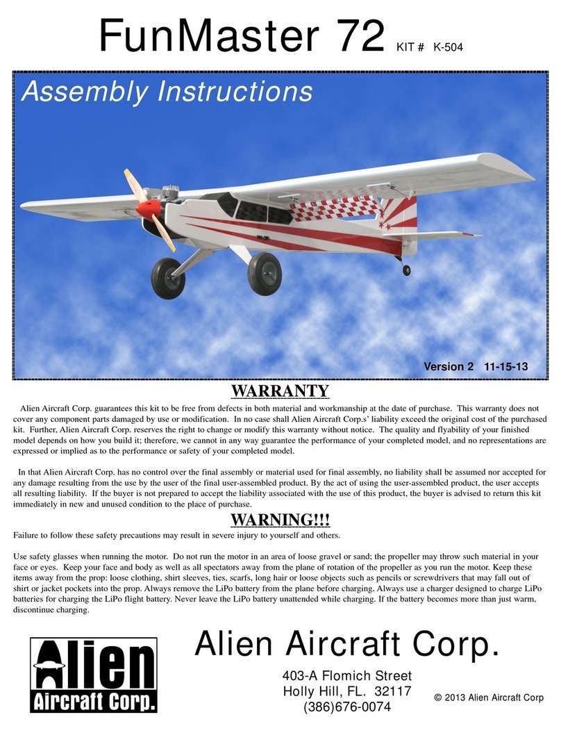
Alien Aircraft Corp FunMaster 72 K-504 User manual

Alien Aircraft Corp
Alien Aircraft Corp Hornet K-107 User manual

Alien Aircraft Corp
Alien Aircraft Corp K-501 User manual

Alien Aircraft Corp
Alien Aircraft Corp P-51D Mustang User manual

Alien Aircraft Corp
Alien Aircraft Corp C-310-B User manual

Alien Aircraft Corp
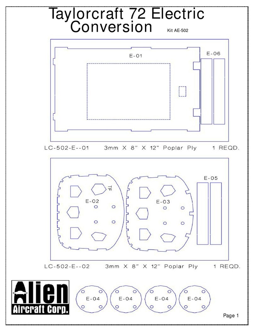
Alien Aircraft Corp Taylorcraft 72 User manual

Alien Aircraft Corp
Alien Aircraft Corp FunMaster 72 User manual

Alien Aircraft Corp
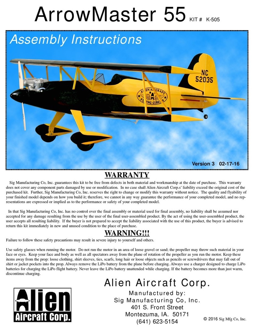
Alien Aircraft Corp ArrowMaster 55 User manual