Alien Aircraft Corp Hornet K-107 User manual

Alien AircraftCorp.
403-AFlomichStreet
HollyHill, FL.32117
(386)676-0074
Hornet
KIT#K-107
WARRANTY
AlienAircraftCorp.guaranteesthiskit tobefree fromdefectsinbothmaterialand workmanshipat thedate ofpurchase.Thiswarrantydoesnot
coveranycomponentpartsdamagedby useormodification.Innocaseshall AlienAircraftCorp.s’liabilityexceedtheoriginal costofthepurchased
kit.Further,AlienAircraftCorp.reservestherighttochangeormodifythiswarrantywithoutnotice.Thequalityandflyabilityofyourfinished
model dependsonhowyou buildit; therefore,we cannotinanywayguaranteetheperformanceofyourcompletedmodel,andnorepresentationsare
expressedorimpliedastotheperformance orsafetyofyourcompletedmodel.
In that AlienAircraftCorp.hasnocontroloverthefinal assemblyormaterial usedforfinal assembly,noliabilityshall beassumednoracceptedfor
anydamageresultingfromtheusebytheuserofthefinal user-assembledproduct.Bytheact ofusingtheuser-assembledproduct,theuseraccepts
all resultingliability.Ifthebuyerisnotpreparedtoaccepttheliabilityassociatedwiththeuseofthisproduct,thebuyerisadvisedtoreturnthiskit
immediatelyinnewandunusedconditiontotheplace ofpurchase.
WARNING!!!
Failuretofollowthesesafetyprecautionsmayresult insevereinjurytoyourselfandothers.
Usesafetyglasseswhenrunningthemotor.Donotrun themotorinanarea ofloosegravel orsand;thepropellermaythrowsuchmaterialinyour
face oreyes. Keepyourfaceandbodyaswell asall spectatorsawayfromtheplaneofrotation ofthepropellerasyourunthemotor.Keepthese
itemsawayfromtheprop:looseclothing,shirtsleeves, ties,scarfs, longhairorlooseobjectssuchaspencilsorscrewdriversthatmayfall outof
shirtorjacket pocketsintotheprop.AlwaysremovetheLiPobatteryfromtheplanebeforecharging.AlwaysuseachargerdesignedtochargeLiPo
batteriesforcharging theLiPoflightbattery.NeverleavetheLiPobatteryunattendedwhile charging.If thebatterybecomesmorethanjustwarm,
discontinuecharging.
AssemblyInstructions
The
TM
©2010 AlienAircraftCorp

Notesaboutthelasercutparts
1...Thefirstthingthatyouneedto doisto identify andmark the partnumbersonthelasercutpartsusingthe drawingsonthe
followingpagesasaguide.
2...Itispossible that several ofthelasercutpartsmaynotbecompletelycutthrough.If thisisthecaseyoucanfree thepartfromthesheet
quicklyusing anX-actoknife.
3...Theslightdiscoloration on theedgesof thelasercutpartsmayberemovedby lightlysandingtheedgeswith400 grit sandpaper.
KitContents:
Yourkit containsthefollowingparts.Pleasecheckyour kitfor anymissingordamagedpartsbeforestarting construction.
WoodBag:
Qty...........Name.............................Description
1............LC-107-01.........................1/16”X4”X24”LaserCutBALSA
1............LC-107-02.........................1/16”X4”X24”LaserCutBALSA
1............LC-107-03.........................1/16”X4”X24”LaserCutBALSA
1............LC-107-04.........................1/16”X4”X24”LaserCutBALSA
1............LC-107-05.........................3/32”X4”X24”LaserCutBALSA
1............LC-107-06.........................1/16”X3”X12”LaserCutBALSA(Maybe1/32”x3”x12”)
1............LC-107-07.........................3/32”X4”X12”LaserCutBALSA
1............LC-107-08.........................3mmX3”X12””LaserCutPOPLARPLY
1............LC-107-09.........................1/16X3”X6”LaserCut BirchPLY
4............MainWingSpars....................3/32”X3/16”X18”BALSA
4............WingTrailingEdges..................1/16”X1/2”X18”BALSA
2............WingLeadingEdges..................1/4”sq.X18”BALSA
8............StringerSpars.......................3/32”X3/32”X18”BALSA
1............LandingGearWire...................1/16”X15”MUSICWIRE
2............Ailerons...........................1/8”LaserCutBalsa
HardwareBag
Qty...........Name.............................Description
4............BlindNuts.........................4-40BlindNuts
1............1/8”x3”BirchDowel................ElevatorJoiner
8............WingCenterSection Sheet.............1/32”X11/2”X3”BALSA
2............3/32”sq.x2”Balsa..................FormerBrace
2............1/16” WheelRetainer.................WheelRetainers
4............ControlHorn........................ControlHorns
3............SigEZHinge.......................Hinges
Misc.LooseParts
Qty...........Name.............................Description
1............K-107PLAN A
1............K-107PLAN B
AdditionalItemsRequired (Not Included inKit)
Note: Thesearepartsthatwehaveusedand arefamiliarwith.Therearemanyotherbrandsavailableandyou maysubstituteotheritemsthatyouaremore
.............comfortablewithorhaveonhand.
Qty.........Name.........................Description
1...........Motor..........................HimaxHC2808-1160BrushlessMotor(AlienAircraft P/N: AE-018)
1...........SpeedControl...................
CastleCreationThunderbird-18ElectronicSpeedControl(AlienAircraft P/N: AE-019)
withconnectorsmatchingmotor&battery
2...........Tail Pushrods....................DubroMicroPushrodSet(AlienAircraftP/N: AH-001)
2...........AileronPushrods.................AlienAircraft "2”x10”PushrodSet(AlienAircraftP/N: AH-003)
1...........Propeller.......................APC7X4SFPropeller(AlienAircraft P/N:AE-023)
2...........Wheels........................1.85"AluminumBushingWheels(AlienAircraft P/N: AH-009)
1...........Velcro.........................6"Velcro(AlienAircraft P/N: AE-012)
1...........MotorMountHardware............2808MotorMountHardware(AlienAircraft P/N: AE-022)
1...........Battery........................3Cell1250MahLipoBattery
1...........CoveringMaterial................1Roll LightWeightCoveringMaterialPlusTrimColors
1...........Radio.........................4ChannelRadiowith4microservos&Receiver
Page2
Page3
Maybe1/32”x3”x12”
XX

BuildingInstructions:
GeneralNote:Covertheplanswithwaxpaper before assembling yourmodeltopreventthepartsfromsticking to
theplan.
BuildingtheTailSurfaces:
1...GlueR-1and R-2together.GlueR-3and R-4together.Sand the
outsideedgesround. Leavethefuselageedgessquare.
BevelthefrontedgeofR-5asshownon theplan, and sand theother
edgesround.
Markthehingelocations and cutthehingeslots. Temporarilyinstall
thehingeswithoutglue.
2...GluetheS-2’stoS-1. Sand oneofthe1/8”x3”dowelsto3/32”
diameter.Jointheelevators(S-3)using thisdowel.Usethestabilizer
asaguide.Trimthedowelifrequiredtoachievetheproper length.
BevelthefrontedgeoftheS-3’sasshownon theplan, and sand the
otheredgesround.
Sand thefrontand ends ofthestabilizer round. Leavethebackedge
square.
Markthehingelocations and cutthehingeslots. Temporarilyinstall thehingeswithoutglue.
BuildingtheFuselage:
3...GluetheF-2doublerstotheinsideoftheF-1R&F-1Lfuselage
sides. Besuretomakearighthand and alefthand side.
Note:Thephotos showalightning holeinthefuselagesides(looks
likewindowsinthecockpit area).Thishasbeeneliminatedfromthe
production kits. Pleasedisreguardit intheassemblyphotos thatfol-
low.
4...Press thefour4-40 blind nutsintothebackofthefirewall (F-7).
Useasmalldrop ofthinC/Atosecuretheminplace.
Page4

5...LightlytackglueformersF-3,F-4, F-5and F-6intoposition on the
rightfuselageside.Useasmallsquaretoposition theseparts90
degreestothefuselageside.
6...Placetheleftfuselagesideintoposition and squareup thefuselage.
Gluetheleftfuselagetotheformers. Makesure thatthefuselageis
squareand completelygluetheformerstothefuselagesides.
7...Gluethefirewall(F-7)intoposition making surethefrontofthe
fuselageisnottwisted.
8...GlueF-8intoposition on thetop frontofthefuselage.
9...Bend thelanding gear wiretoshapeusing thepatternon theplan.
Leavetheaxleslong until you mountthewheels.
Page5

10...Placethelanding gearwireintothefuselagetightlyagainstthe
frontofF-3. Gluesecurelyintoposition.
11...GluepartsF-9Land F-9Rintoposition. Thesepartsshouldbe
flush withthenotchesinthefuselageside.
12...GlueF-10 intoposition. Itshouldfit downintothenotchesin
partsF-2and F-9.
13...GlueF-11intoposition on thebottomofthefuselage.Glueto
F-10 aswell asthefuselagesidesand thefirewall.
14...GlueF-12 tothetop ofthefuselage.Slightlywettheoutsideof
theparttoallowit tocurve/bend easier.
Page6
Flush

15...GlueF-13 tothetop ofthefuselage.Slightlywettheoutsideof
theparttoallowit tocurve/bend easier.
16...Pull and gluetherearofthefuselagesidestogether.
17...SlideformerF-14 intoposition. Adjustthebackend until the
fuselageisstraightand square.Gluetheformer inplace.
18...Gluethe3/32”sq. reinforcementstothetop and bottomofF-15
asshownon theplan.
19...PlaceformerF-15 intoposition and glueinplace.
Page7

20...GlueF-16 intoposition on thebottomrear ofthefuselage.
21...GlueF-17 intoposition on thetop ofthefuselage.
BuildingtheHatch:
22...GluepartsH-2, H-3and H-4intoposition on thehatch(H-1)
using thelaser marking asaguide.GluepartsH-5and H-6together.
Makesure thattheyare90 degreestoeachother.
23...PlacepartsH-7intoposition on thehatch. InsertH-5/6position
toestablish theproperspacing fortheH-7’s. Usethetipofastraight
pintoapplyatiny amountofgluetotheoutsideedgesoftheH-7’s.
Useextremecaretomakesurethatyou DO NOTgluetheH-5/6slider
intoposition!!!
24...WiththeH-5/6sliderinposition, carefullygluethetwoH-8
piecesintoposition. Usethetipofastraightpintoapplyatiny
amountofgluetotheoutsideedgesoftheH-8’s. Useextremecareto
makesure thatyou DO NOTgluetheH-5/6slider intoposition!!!
Page8

25...Testfitthehatchtothebottomofthefuselage.Thefronttab
(H-2)slidesunder partF-11. Slidethehatchsliderforwardand press
thebackend ofthehatchdownon thefuselage.Movethesliderback
toinsertitintotheslotinformerF-6. You cantrimtheoutsideedges
ofH-2tocenterthefrontofthehatchifrequired.
26...Useasanding blocktosand all ofthefuselagesurfacessmooth
and flat.Nowlightlysand theedgesofthefuselageround. Sand the
backedgesofpartsLGround. Leavethetop, bottomand front
square.
27...Followthedashedlinestocutand removethefuselagesidesto
maketheslotforthestabilizer.
BuildingtheWing:
28...Covertherightwing planwithwaxpaper topreventtheparts
fromsticking totheplan.
29...Pinthelower3/32”x3/16”lowermainspar.Align theinboard
end withthewing center line.Theoutboardend willextend pastthe
W-9rib.
30...Glueribs W-1thruW-9intoposition. Useasmallsquaretomake
sure thattheyare90 degreestothebuilding board.
Page9

31...Slidethelower1/16”x1/2”trailing edgeintoposition intheslots
betweentheribs and theirsupporttabs. Aftermaking surethatitis
positionedproperly,gluetotheribs.
32...Gluethe3/32”x3/16”top sparand the1/4”sq. leading edgeinto
position.
33...Gluethetop 1/16”x1/2”trailing edgeintoposition.
34...Gluetheshear webs (AthruG) intoposition on thefrontfaceof
thespars.
35...Gluethetwo3/32”sq. stringer sparsintoposition.
Page10

36...Usetwoofthe1/32”x11/2”sheetstosheetthecenterofthe
wing. Thesheetshouldbecuttofit betweenthesparsasshownon
theplan.
37...GlueW-10 intoposition tothesparand ribW-3.
38...Removethewing fromtheplan. Cutofftheribsupporttabsfrom
theribs.
39...Gluethebottomstringersparsintoposition. Usetwoofthe1/32”
x11/2”sheetstosheetthecenter ofthewing. Thesheetshouldbe
cuttofitbetweenthesparsasshownon theplan.
40...Trimthespars, leading edgeand trailing edgeflush witheachend
ofthewing.
Page11

41...Gluetwo W-11ribs totheend ofthewing.
42...Sand theleading edgeround tomatchtheprofileshownon the
plan. Nowsand thewing smoothall over.
43...Nowrepeatsteps 27 thru42 tobuildtheleftwing.
44...Sand thebackedgesand theends oftheailerons round. Taper
thefrontedgeoftheailerons totheshapeshownon theplan.
Markand cutthehingeslotsintheailerons and thewing. Install the
hingeswithoutglueand testfittheailerons tothewing.
45...Cutslotsinboth W-1ribs on thedashedlinestoacceptfuselage
formerF-4asshownon theplan.
46...Testfitthewings ontothefuselage.Theservo mounts(W-10)
shouldbeon thebottomofthewings. Whenviewedfromthefront,
thetops ofthewing shouldbeflatand paralleltothetop ofthefuse-
lage.
Page12

Covering:
47...Sand allpartssmoothwith400 gritsandpaper.Coverthemodelwithalightweightiron on covering material.
Note:
After themodeliscoveredyou mustcheckthetail surfacesand wings forwarpsortwists. Ifthereareany
theycanberemovedby twisting thepartsstraightand heating thecovering.
FinalAssembly:
48...Cutthecovering awayfromthestabilizer intheareathatmakes
contactwiththefuselage.Cutthecovering awayfromthestabilizer
slotinthefuselage.
49...Placethestabilizerintoposition inthefuselage.Makesurethat
itisstraightand square and thenglueit intoposition.
50...Attachtheelevatorswiththehingesand glueinplace.
51...Carefullycutthecovering awayfromareason thefuselagethat
willmakecontactwiththefins. Placethefins intoposition and make
sure thattheyarestraightand square.Gluethefins intoposition.
Attachtherudder withthehingesand glueinplace.
52...Insertthepushrod housings intotheexit slotsinthebackofthe
fuselage.Theyshouldextend outabout21/2”fromthefuselagetop.
Thefrontends shouldpass thrutheslotinformerF-6. Gluethehous-
ings totherear exits. Donotgluethefrontends totheformeratthis
time.
Page13

53...Screwtheservos totheservo tray.
54...Gluetherudder and elevatorcontrolhorns intoposition. Drill
1/16”holesforthepins topassthru. Whentheglueisdry,cutoffthe
excess pins flush..
55...Install thepushrods intothehousings. Securetherear ofthe
pushrods withMiniE/ZLinks.
Thefrontends are attachedtotheservos withMiniE/ZConnectors.
Gluethepushrod housings totheformer.
56...Attachtheailerons tothewings withthehingesand glueinplace.
Page14

57...Screwtheservos intoposition on thebottomofthewing. Feed
theservo wiresthrough theholesinribs W-2and W-1.
58...Gluetheaileron controlhorns intoposition. Drill 1/16”holesfor
thepins topass thru. Whentheglueisdry,cutofftheexcess pins
flush.
59...Install thepushrods. Slidethe1/32”id. aluminumtubestiffen-
ersontothepushrod. Attachtherearofthepushrods tothehorns with
MiniE/ZLinks.
60...Thefrontends are attachedtotheservos withMiniE/ZConnec-
tors. Whentheservos areinneutraltheservo armshouldbe90
degreestothepushrod. Nowcenterthealuminumtubeson the
pushrods. Place adrop ofthinC/Agluetoeachend ofthetubesto
secureitontothepushrods.
61...Slidethewings ontothefuselage.Makesurethatthetrailing
edgesofthewings areintheproper position on thefuselagesides.
Placepart“XX”againstthefuselagesideasshownand twistthewing
asrequiredtomakecontactwiththetop ofXX.
Marktheribposition on thefuselageside.Removethewings and
carefullycutthecovering awayfromthefuselageinthelocation that
thewings willmakecontact.
62...Gluethewings intoposition using epoxy.Spreadtheglueinto
theslotinthewing covering thesparsand shearweb. Also applyglue
totheend ofthewing. Slidethewing ontothefuselage.Adjustfor
theproper position ofthewing trailing edgeusing partXX,and make
sure thatthetop ofthewing isparallelwiththefuselagetop. Holdin
thisposition until thegluehascured.
Page15

63...AttachpartsLGtothebackofthelanding gearwireswithasmall
amountofC/A.Wrapa1/2”widestripofcovering materialaround
thefrontofthelanding gear wire and iron intoposition tosecureparts
LGtothelanding gearwire.
64...Putthewheelson themodeland pressthewheelretainersinto
position. Withtheretainersinplace,cutofftheexcess wireaxleflush
withtheretainer.
65...Securethemotormounttothefrontofthemotorwiththefour
flatheadscrews. Nowboltthemotortothefirewall with4-40 screws
and aluminumtubespacers. Note:Becausethewireson themotor
areshort,pass thewiresfromthespeedcontrollerthruthefirewall
and attachtothemotorbefore mounting themotortothefirewall.
66...Securethespeedcontrollertothefuselagewithvelcro. The
speedcontrolcanbemountedon thefuselagesideoron thefrontof
formerF-4.
67...Plug thespeedcontroland servos intothereceiverand attachthe
receivertothefuselagesidewithvelcro. Pass thereceiver antenna
backand outthrough therearofthefuselage.
Page15

68...WITHTHEPROPELLERREMOVED...Turnthetransmitteron. Placethethrottlestickinthelowposition.
Plug thebatteryintothespeedcontroller.Checkthemotorforproperoperation and direction ofrotation. Followthe
instructions withthespeedcontrollertomakeany adjustments.
69...Checktheservos forproper operation and direction. Adjustthecontrolthrowstothevaluesshownon theplan.
Nowdisconnectthebatteryand thenturnoffthetransmitter.
70...Placethebatteryinthenoseofthemodel.Attachthepropeller.
71...Checkthebalanceofthemodel.Itshouldbalanceattheposition shownon theplan. Movethebatteryforward
orafttoachievetheproper balance.Usevelcrotosecurethebatteryinthemodelinthisposition. Note:Ifmoving
thebatterywill notachievetheproper balance,you will havetoadd weighttothenoseortail.Glueany weight
securelytothemodel.
72...Yourmodelisnowready tofly.Fullychargethetransmitter and airbornebatterybeforeattempting toflythe
model.Always rangecheckand do athorough pre-flightofthemodelbeforeeveryflight.Always followestab-
lishedsafetyguidelineswhileoperating themotor,radioand flying yourmodel.
LIPOBATTERYSAFETYALERT
LithiumBatteryFires
Lithiumbatteries arebecomingverypopularforpoweringthecontrolandpowersystemsinourmodels. Thisistruebecauseoftheir veryhighenergyden
-
sity(amp-hrs/wt.ratio)comparedtoNiCd’sorotherbatteries. Withhighenergycomesincreasedriskintheiruse. TheprincipalriskisFIREwhichcan
resultfromimpropercharging,crashdamage,orshortingthebatteries.All vendorsofthesebatteries warntheir customersofthisdangerandrecommend
extreme cautionintheir use.Inspiteofthis,manyfires haveoccurredasaresult oftheuseofLithiumPolymerbatteries resultinginlossofmodels,auto
-
mobiles,andotherproperty.Homes andgaragesandworkshopshavealsoburned.Alithium batteryfireisveryhot(severalthousanddegrees)andisan
excellentinitiatorforancillary(resulting)fires.FireoccursduetocontactbetweenLithiumandoxygenintheair.It does notneedanyothersourceofigni
-
tion,orfueltostart,andburnsalmostexplosively. These batteries mustbeusedinamannerthatprecludes ancillaryfire. Thefollowingisrecommended:
1.Store,andcharge,inafireproofcontainer; neverinyourmodel.
2.Chargeinaprotectedareadevoidofcombustibles.Alwaysstandwatchoverthechargingprocess.Neverleavethechargingprocess unattende
3.Intheeventofdamagefromcrashes,etc,carefullyremovetoasafeplace foratleastahalf hourtoobserve.Physicallydamagedcellscoulderuptinto
flame andaftersufficienttimetoensuresafety,shouldbediscardedinaccordance withtheinstructionswhichcamewiththebatteries.Neverattemptto
chargeacell withphysicaldamage,regardlessofhowslight.
4.Alwaysuse chargersdesignedforthespecificpurpose,preferablyhavingafixedsettingforyourparticularpack.Manyfiresoccurinusing
selectable/adjustablechargersimproperlyset.NeverattempttochargeLithiumcellswithachargerwhichisnotspecificallydesignedforchargingLithium
cells.Neveruse chargersdesignedforNickelCadmiumbatteries.
5.Use chargingsystemsthatmonitorandcontrolthechargestateofeachcell inthepack.Unbalancedcellscanleadtodisasterif itpermitsoverchargeofa
singlecell inthepack.If thebatteries showanysignofswelling,discontinuechargingandremovethemtoasafeplaceoutsideas theycoulderuptinto
flames.
6.Mostimportant: NEVERPLUG IN ABATTERYAND LEAVEITTOCHARGEUNATTENDEDOVERNIGHT.Seriousfires haveresultedfromthis
practice.
7.Donotattempttomakeyourownbatterypacksfromindividualcells.
Thesebatteries CANNOTbehandledandchargedcasuallysuchashas beenthepracticeforyearswithothertypes ofbatteries. Theconsequence ofthis
practicecanbeveryseriousresultinginmajorpropertydamageand/orpersonalharm.
Page16
Table of contents
Other Alien Aircraft Corp Toy manuals

Alien Aircraft Corp
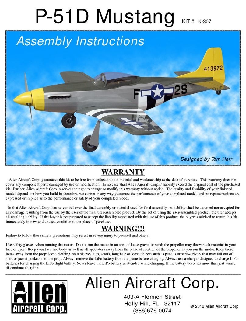
Alien Aircraft Corp P-51D Mustang User manual

Alien Aircraft Corp
Alien Aircraft Corp K-308 User manual

Alien Aircraft Corp
Alien Aircraft Corp Taylorcraft 72 User manual

Alien Aircraft Corp
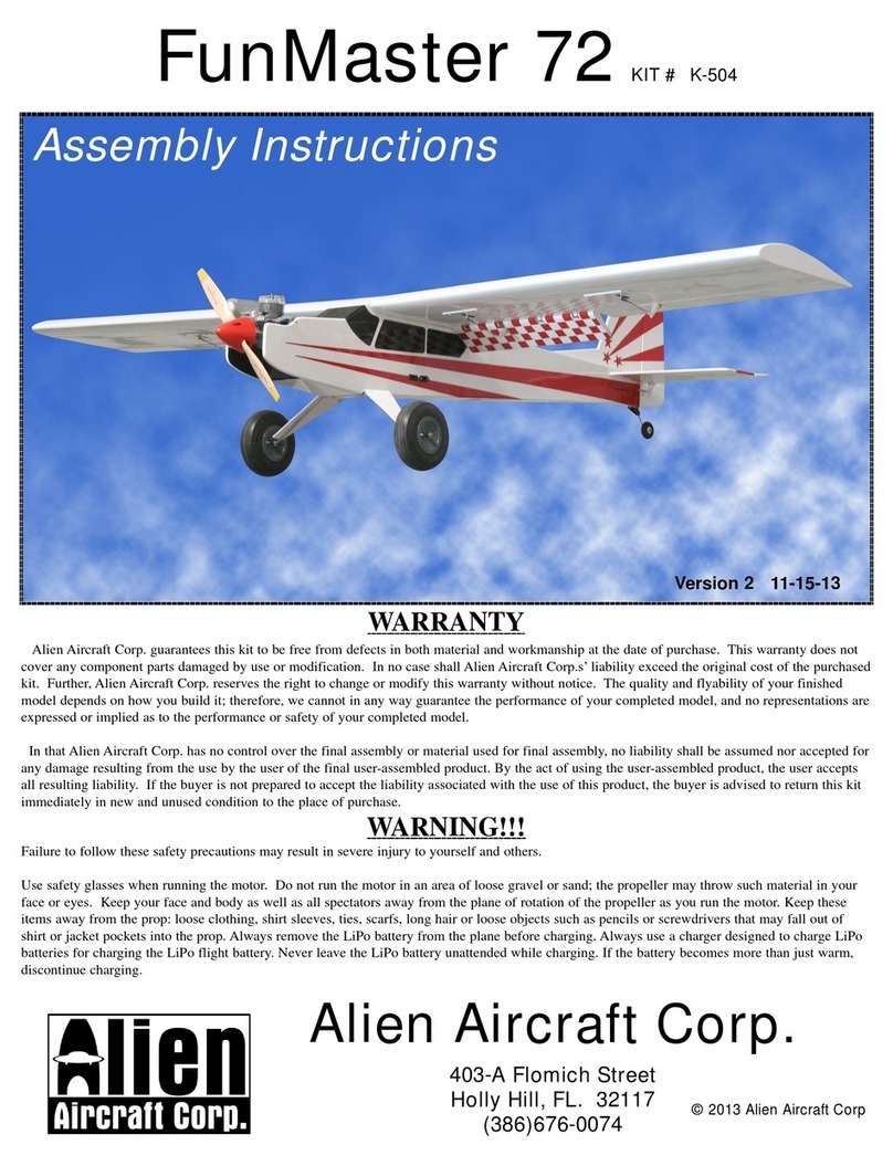
Alien Aircraft Corp FunMaster 72 User manual

Alien Aircraft Corp
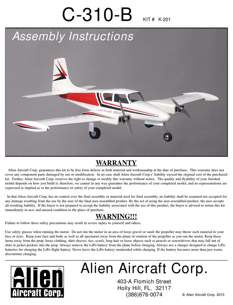
Alien Aircraft Corp C-310-B User manual

Alien Aircraft Corp
Alien Aircraft Corp FunMaster 72 K-504 User manual

Alien Aircraft Corp
Alien Aircraft Corp ArrowMaster 55 User manual

Alien Aircraft Corp
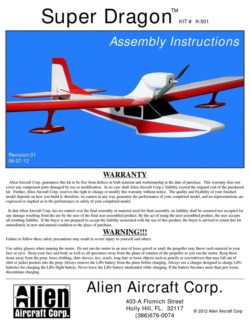
Alien Aircraft Corp K-501 User manual