Alien Aircraft Corp K-501 User manual

AlienAircraftCorp.
403-AFlomichStreet
HollyHill,FL.32117
(386)676-0074
SuperDragon KIT#K-501
WARRANTY
AlienAircraftCorp.guaranteesthiskit tobefreefromdefectsinbothmaterialand workmanshipatthedateofpurchase.Thiswarrantydoesnot
coveranycomponentpartsdamagedby useormodification.Inno caseshall AlienAircraftCorp.s’liability exceedtheoriginalcostofthepurchased
kit.Further, AlienAircraftCorp. reservestherighttochangeormodifythiswarrantywithoutnotice.Thequality and flyability ofyourfinished
modeldependsonhowyoubuildit; therefore,wecannotinanywayguaranteetheperformanceofyourcompletedmodel,and norepresentationsare
expressedorimpliedastotheperformance orsafetyofyourcompletedmodel.
InthatAlienAircraftCorp. hasno controloverthefinalassemblyormaterialusedforfinalassembly,noliabilityshall beassumednoracceptedfor
anydamageresulting fromtheuseby theuserofthefinaluser-assembled product.Bytheactofusingtheuser-assembledproduct,theuseraccepts
all resultingliability.Ifthebuyerisnotpreparedtoaccepttheliabilityassociatedwiththeuseofthisproduct,thebuyerisadvised toreturn thiskit
immediatelyinnewand unused condition totheplaceofpurchase.
WARNING!!!
Failuretofollowthesesafetyprecautionsmayresult insevereinjurytoyourselfandothers.
Usesafetyglasseswhenrunning themotor.Donotrunthemotorinanareaofloosegravelorsand;thepropellermaythrowsuchmaterialinyour
faceoreyes.Keepyourface and body aswell asall spectatorsawayfromtheplaneofrotation ofthepropellerasyou run themotor.Keepthese
itemsawayfromtheprop:looseclothing, shirtsleeves,ties,scarfs,longhairorlooseobjectssuchaspencilsorscrewdriversthatmay fall outof
shirtorjacketpocketsintotheprop. AlwaysremovetheLiPobatteryfromtheplanebeforecharging. AlwaysuseachargerdesignedtochargeLiPo
batteriesforcharging theLiPoflightbattery.NeverleavetheLiPobatteryunattendedwhilecharging. Ifthebatterybecomesmorethanjustwarm,
discontinuecharging.
AssemblyInstructions
TM
©2012AlienAircraftCorp
TM
Revision:01
09-07-12

Notesaboutthelasercutparts
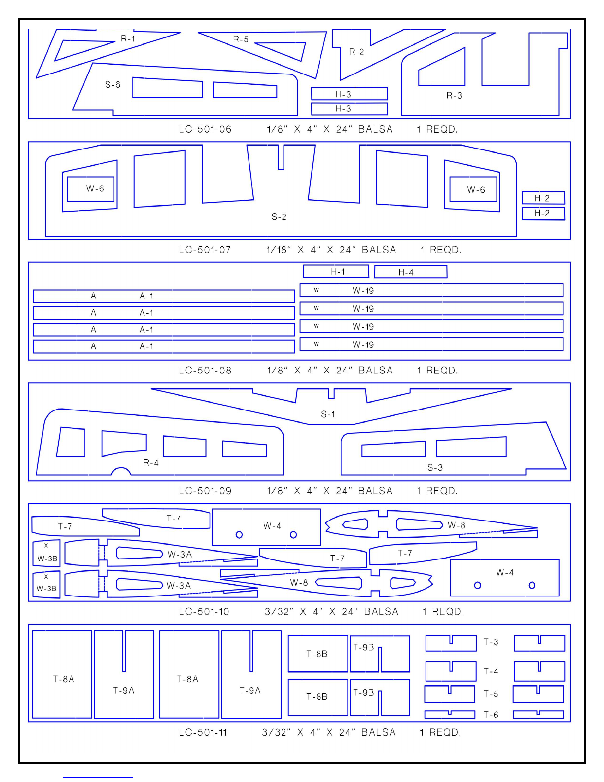
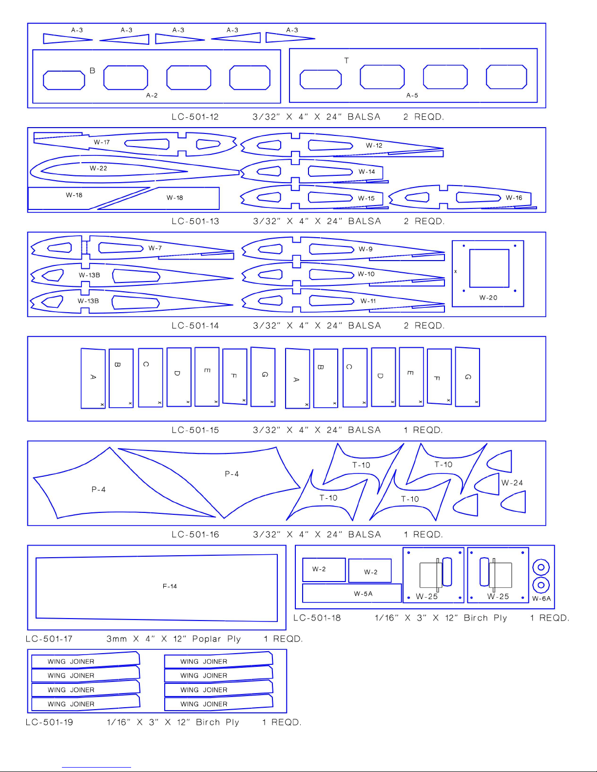
1...Thefirstthingthatyouneedtodoistoidentifyandmarkthepartnumbersonthelasercutpartsusingthedrawingsonthefollowingpagesasaguide.
2...It ispossiblethat severalofthelasercutpartsmaynotbecompletelycutthrough.IfthisisthecaseyoucanfreethepartfromthesheetquicklyusinganX-actoknife.
3...Theslightdiscolorationontheedgesofthelasercut partsmayberemovedbylightlysandingtheedgeswith400 grit sandpaper.
KitContents:
Yourkit containsthefollowing parts.Pleasecheckyourkitforanymissingordamagedpartsbeforestartingconstruction.
WoodBag: Qty.. ... .Name. . ... ... ... ... ... . ... ... ... ... ... . ... ..Description
2... ... .LC-501-01. ... ... ... ... . ... ... ... ... ... . ... ..3mm X5”X24””Laser CutPOPLAR PLY
2... ... .LC-501-02. ... ... ... ... . ... ... ... ... ... . ... ..3mm X7”X24””Laser CutPOPLAR PLY
1. ... ... .LC-501-03. ... ... ... ... . ... ... ... ... ... . ... ..3mm X5”X24””Laser CutPOPLAR PLY
1... ... .LC-501-04. ... ... ... ... . ... ... ... ... ... . ... ..3mm X7”X24””Laser CutPOPLAR PLY
1. ... ... .LC-501-05. ... ... ... ... . ... ... ... ... ... . ... ..3mm X7”X24””Laser CutPOPLAR PLY
1... ... .LC-501-06. ... ... ... ... . ... ... ... ... ... . ... ..1/8” X4” X24” LaserCut BALSA
1... ... .LC-501-07. ... ... ... ... . ... ... ... ... ... . ... ..1/8” X4” X24” LaserCut BALSA
1. ... ... .LC-501-08. ... ... ... ... . ... ... ... ... ... . ... ..1/8” X4” X24” LaserCut BALSA
1... ... .LC-501-09. ... ... ... ... . ... ... ... ... ... . ... ..1/8” X4” X24” LaserCut BALSA
1... ... .LC-501-10. ... ... ... ... . ... ... ... ... ... . ... ..3/32”X4” X24” LaserCut BALSA
1. ... ... .LC-501-11. ... ... ... ... . ... ... ... ... ... . ... ..3/32”X4” X24” LaserCut BALSA
2... ... .LC-501-12. ... ... ... ... . ... ... ... ... ... . ... ..3/32”X4” X24” LaserCut BALSA
2... ... .LC-501-13. ... ... ... ... . ... ... ... ... ... . ... ..3/32”X4” X24” LaserCut BALSA
2. ... ... .LC-501-14. ... ... ... ... . ... ... ... ... ... . ... ..3/32”X4” X24” LaserCut BALSA
1... ... .LC-501-15. ... ... ... ... . ... ... ... ... ... . ... ..3/32”X4” X24” LaserCut BALSA
1... ... .LC-501-16. ... ... ... ... . ... ... ... ... ... . ... ..3/32”X4” X24” LaserCut BALSA
1... ... .LC-501-17. ... ... ... ... . ... ... ... ... ... . ... ..3mm X4”X12”LaserCutPOPLAR PLY
1... ... .LC-501-18. ... ... ... ... . ... ... ... ... ... . ... ..1/16”X3” X12” LaserCut BirchPly
1... ... .LC-501-19. ... ... ... ... . ... ... ... ... ... . ... ..1/16”X3” X12” LaserCut BirchPly
3. ... ... .FuselageSheet... ... ... . ... ... ... ... ... . ... ..1/8” x4” x24”Balsa
6. ... ... .Tail Sheet. ... ... ... ... . ... ... ... ... ... . ... ..1/16”x4”x24” Balsa
5. ... ... .Wing&CenterSection Sheet. ... ... ... ... . ... ..3/32”X4” X24” Balsa
4. ... ... .WingLeading EdgeSheet. ... ... ... ... ... . ... ..3/32”x3”x30” Balsa
4. ... ... .WingTrailingEdgeSheet. ... ... ... ... ... . ... ..3/32”x11/2” x18”Balsa
4. ... ... .WingTrailingEdgeSheet. ... ... ... ... ... . ... ..3/32”x1”x18” Balsa
1. ... ... .K-501PLAN A
1. ... ... .K-501PLAN B
5. ... ... .FuselageStringers... ... . ... ... ... ... ... . ... ..1/8” sq. X12” Balsa
1. ... ... .Nose Block... ... ... ... . ... ... ... ... ... . ... ..1/2” x3” x4”Balsa
4. ... ... .OutboardMainWing Spars.. ... ... ... ... . ... ..1/4” x3/8” x30”Balsa
1. ... ... .TipFloat FrontBlock... . ... ... ... ... ... . ... ..3/4” x1” x5”Balsa
1. ... ... .TipFloat RearBlock. ... . ... ... ... ... ... . ... ..1/2” x3/4” x5” Balsa
2. ... ... .WingLeading Edge.. ... . ... ... ... ... ... . ... ..3/8” x3/8” x30”Balsa
2. ... ... .Center SectionMainWingSpars. ... ... ... . ... ..1/4” x3/8” x5” Spruce
Hardware Bag
Qty.. ... .Name. . ... ... ... ... ... . ... ... ... ... ... . ... ..Description
4. ... ... .MotorMount BlindNuts. . ... ... ... ... ... . ... ..6-32 Blind Nuts
1... ... .Elevator JoinerDowel... . ... ... ... ... ... . ... ..1/4” x41/2” BirchDowel
2... ... .WingDowels. ... ... ... . ... ... ... ... ... . ... ..1/4” x1” BirchDowel
2... ... .WingBolts... ... ... ... . ... ... ... ... ... . ... ..1/4-20 x1” Nylon Screw
4. ... ... .Control Horn. ... ... ... . ... ... ... ... ... . ... ..Aileronand Tail ControlHorns
15... ... .Aileron Servo,Cowl &AileronHornScrews.. . ... ..#2X1/2”Sheet MetalScrew
4. ... ... .Tail ControlHornScrews. ... ... ... ... ... . ... ..2-56 x1/2” MachineScrew
40”.. ... .WingJoint Tape.. ... ... . ... ... ... ... ... . ... ..1”x40”DacronTape
Page2

KitContents:
Misc.LooseParts
Qty... . ... ..Name... ... ... . ... ... ... ... ...Description
1.. ... . ... ..K-501 PlasticCowlSet1leftand 1right
1.. ... . ... ..K-501 PlasticNacelleSet 1leftand 1right
AdditionalItemsRequired(NotIncludedinKit)
Qty... .Name... ... ... ... ... . ... ...Description
1.. ... .Motor.. ... ... ... ... . ... ....HimaxHC3528-0800BrushlessMotor( AlienAircraftP/N: AE-040)
1.. ... .SpeedControl.. ... ... . ... ...CastleCreation PhoenixICE 50ElectronicSpeedControl( AlienAircraftP/N:AE-041)
1.. ... .BatteryConnector. ... . ... ...MaleDeansUltra Styleconnector (AlienAircraft P/N:AE-027)
1.. ... .ArmingSwitch. ... ... . ... ...Arming Switchwith12 awg&Dean'sUltra StyleConnectors( AlienAircraftP/N:AE-048)
1.. ... .MotorWire Extension. . ... ...10” 3wireextension #12 wire...3.5mmconnectors( AlienAircraftP/N: AH-045)
1.. ... .Battery. ... ... ... ... . ... ...4Cell5000Mah Lipo Battery30C
1.. ... .BatteryExtension.. ... . ... ...7”BatteryExtension DeansUltraStyleconnectors( AlienAircraftP/N: AE-046)
1.. ... .HeatShrinkTube.. ... . ... ...3/16”HeatShrinkTube( AlienAircraft P/N:AE-029)
2.. ... .Tail Pushrods.. ... ... . ... ...Dubro30” LaserRods(1pair) ( AlienAircraft P/N:AH-013)
2.. ... .Aileron Pushrods.. ... . ... ...12”Aileron 2-56 Pushrods(1pair)( AlienAircraftP/N: AH-014)
1.. ... .Propeller... ... ... ... . ... ...APC11x7EPropeller( AlienAircraft P/N:AE-042)
2.. ... .Velcro.. ... ... ... ... . ... ...6"Velcro( AlienAircraftP/N: AE-012)
1.. ... .MotorMountHardware... ...3528-0800MotorMountScrews( AlienAircraft P/N:AE-043)
1.. ... .CoveringMaterial. ... . ... ...2RollsCoveringMaterialPlusTrimColors
15. ... .Hinges.. ... ... ... ... . ... ...C/AorPinStyleHinges
1.. ... .Radio... ... ... ... ... . ... ...4ChannelRadiowithReceiver
2.. ... .Tail Servos. ... ... ... . ... ...HiTecHS-311Standard Servosor Equivalent
2.. ... .Aileron Servos. ... ... . ... ...HiTecHS-81MicroServosorEquivalent
2.. ... .Aileron Servo Extensions... ...12” Servo Extensionstofityourradio
1.. ... .Aileron “Y”Connector. ... ...6”“Y”Connector tofit yourradio
1.. ... .Aileron Servo Extension. ... ...6”ServoExtensionstofit yourradio
WARNING......EXTREMEDANGER:
Electricmotors,propellers andbatteriespowerfulenoughtofly thismodelare extremely dangerous.These motors, pro-
pellersandbatteriescan causeseriouspropertydamage, seriousbodily injury anddeath.Maximumsafety precautionsmust
be observedatalltimeswheninstalling,maintainingandoperatingthese items.Maximumsafetyprecautionsmustbe
observedatalltimeswhen assembling,maintainingandoperatingthismodel.You mustunderstandandfollowall ofthe
manufacturesoperatingandsafetyinstructionsforeverypiece ofequipmentandcomponentusedwiththismodel.
YOUMUSTUSEANARMINGSWITCHBETWEENTHEBATTERYAND SPEEDCONTROLLER.
Ifyouhave anydoubtaboutthepropersafety precautions,you mustcontactthe manufacturestoobtainthe operatingand
safetyinstructionsforeverypiece ofequipmentandcomponentusedwiththismodel.
Youmustreadand followtheimportant notesonthecoverandonpage41 ofthismanual.
Page3

Page4

Page5

Page6

BuildingInstructions:
GeneralNote:Covertheplanswithwaxpaperbeforeassembling yourmodeltopreventthepartsfromsticking to
theplan.
BuildingtheTail Surfaces:
1...GlueS-1and S-2togetherasshown.
2...Gluetogethertwopiecesof1/16”x4”x24”balsasheetasshown
tomakethestabilizerskin.
3...Gluethissheettoonesideofthestabilizer.
4...Trim thesheetflushwithS-1/S-2.Nowsheetand trim theoppo-
sitesideas you didthefirst. Besuretocutouttherudderslot.
5...Use1/16”balsatosheetbothsides oftheelevators(S-3).
6...Jointheelevators(S-3)using the1/4”x4-1/2”dowel.Usethesta-
bilizeras aguide.Trim thedowelifrequiredtoachievetheproper
length.
Page7

7...BevelthefrontedgeoftheS-3’sas shownon theplan,and sand the
otheredgesround.
Sand thefrontand ends ofthestabilizerround.Leavethebackedge
square.
Markthehingelocations and cutthehingeslots.Temporarilyinstall
thehingeswithoutglue.
8...GlueR-2and R-3together.Use1/16”balsatosheetbothsidesof
R-1,R-2/3,R-4and R-5.GlueR-1tothefrontofR-2/R-3.
9...BevelthefrontedgeofR-4asshownon theplan,and sand the
otheredgesround.
Markthehingelocations and cutthehingeslots inR-3, R-4and R-5.
Temporarilyinstall thehingeswithoutglue.Sand theoutsideedges
round. Leavetheotheredgessquare.
BuildingtheFuselage:
10...Assemblethefuselagesidesusing partsF-1Aand F-1B.
11...GluetheF-2and F-3doubelers totheinsideofthefuselagesides.
Besuretomakearighthand and alefthand side. Usethedrawing
on theplantoproperlylocatethedoublerson thefuselagesides.
Page6

12...GluethetwoF-4’stogetherand glueF-5BtoF-5A.
13...LightlytackglueformersF-4, F-5,servo trayF-6and F-7into
position on therightfuselageside. F-5Bison thebacksideofF-5.
14...Place theleftfuselagesideintoposition and squareup thefuse-
lage.Gluetheleftand rightfuselagesidestightlyagainstF-6.Make
surethatthefuselageissquareand completelygluetheformerstothe
fuselagesides.
15...Place formerF-8intoposition and pull therearofthefuselage
sidestogether.Adjustthebackend until thefuselageisstraightand
square.Gluethefuselagesidestogetherand gluetheformerinplace.
16...Place formerF-9intoposition and glueinplace.
Page7

17...GlueF-10 intoposition on thetop rearof
thefuselage.Spreadand squeezethesidesas
requiredtogetF-10 tofit intheproperposi-
tion.
18...Usethe1/8”x4”x24”balsato
sheetthebottomrearofthefuselage.
Thisshouldbedoneinpieces withthe
graingoing across thefuselagefrom
lefttoright.
19...Whentheglueisdry,trim thesheet
flushwiththefuselagesides.
20...GlueformersF-11,F-12 and F-13 intoplace in
thefrontofthefuselage. Thereisasmall “x”
markedon F-13.Thisisthetop side. Usecareto
keepthefuselagestraightand square.
21...Gluevelcrotothetop sideoftheF-14 battery
tray.Makeavelcrostrapand glueit tothebottomof
thebatterytray.
Page8

22...Gluethebatterytrayintoposition on
theformersasshown.Usetheplanasa
guidetoestablishtheproperforeand aft
placement.
23...GlueThe1/8”x12”balsastripsinto
place inthenotchesinthebottomofthe
fuselageformers.Thefrontendsshould
stop atformerF-12.Thebackends
shouldbecutflushwiththebackofF-5.
24...Usethe1/8”x4”x24”balsatosheet
thebottomfrontofthefuselage.This
shouldbedoneinpieceswiththegrain
going acrossthefuselagefromlefttoright.
Whentheglueis dry,trimthesheetflush
withthefuselagesides.
25...Trim thetop offormerF-12 awayatthedashed
lines.
26...Usethe1/8”x4”x24”balsatosheetthetop
frontofthefuselage.Thisshouldbedoneinpieces
withthegraingoing acrossthefuselagefromleftto
right.Whentheglueisdry,trim thesheetflushwith
thefuselagesides.Donotsheetthewindshieldarea
atthis time.
Page9

27...GluethetwoF-15’sintoplace on thetop ofthefuselageinthe
notchesintheF-2doublersjustinfrontofformerF-7.
BuildingtheWingCenterSection:
28...Pinthelower1/4”x3/8”x5”spruce lowermainspartotheplan.
Theends will extend slightlypasttheW-3ribs.
29...GluethetwoW-1Atogether
30...GluetheW-1BribstoeachsideoftheW-
1A’s.OnlyoneoftheW-1B’shas thesupport
tabon thebottomrear.Itdoesn’tmatterifyou
putit on theleftorrightside.
31...GluetheW-3Bdoublerstothefrontofthe
W-3Aribs.Besuretomakealeftand rightas
shown.
Page10

32...GluetheW-1ribintoposition on thelowermainspar.Therib
shouldbe90 degreestothebuilding board.
33...GluetheW-2shearwebs intoposition on thefrontofthesparon
eachsideoftheW-1rib.Theyshouldbetightagainsttheriband
alignedwiththesparslotinthetop oftherib.
34...Place theW-3ribsontothelowerspar. Theyshouldbetight
againsttheW-2shearwebs.TheW-3B’sshouldbeon theinboard
sides.Whenintheproperposition,gluetheribstothespar.
35...Putthe1/4”x3/8”x5”spruce top mainsparintoplace. Theends
will extend slightlypasttheW-3ribs.Glueit totheribsand shear
webs.
Page11

36...SlideoneW-4intotheslotson thebottomoftheribsasshown.
Centeritand makesureit isfullyforwardintheslotsand gluetothe
ribs.
37...GluetheotherW-4intoposition on top oftheribs.
38...UsesandpapertotaperthetwoW-6’ssotheyfit intothegap
betweenthetwoW-4’s.Theyshouldfit tightand bepositionedasfar
backaspossible.GluetheW-6’sinplace.
39...GluethetwoW-5B’sand W-5Atogetheras
shown.
Page12

40...Place theW-5assemblyintoplacebetweentheW-3ribs.It
shouldbealignedup and downwiththefrontcorners oftheW-3ribs,
and backagainsttheW-3Bdoublersand theW-1ribs.Wheninthe
properposition,glueinplace.
41...Usethe3/32”x4”x24”balsatosheetthetop ofthewing center
section. Thegrainshouldrun lefttoright. Leavetheedges slightly
long on thesides and front.
Cutthesheetawayfromthemotorpylon slotintheW-1Aribs.
42...Removethecentersection fromtheplan.Cut
thesupporttabs fromthebottomoftheribs.Use
the3/32”x4”x24”balsatosheetthebottomof
thewing centersection.Thegrainshouldrun left
toright.
43...Whentheglueisdry,trim thesparsand sheet
flushwiththeW-3ribs and thefrontofW-5.Sand
thetop and bottomofthecentersection smooth.
44...Sand abevelaround theedgesoftheW-6A’s.
Gluethemon thetop ofthecentersection, cen-
teredon theholesinW-4.Cutthetop sheetaway
fromtheforwardpylon slotintheW-1rib.
Page13

45...Using a1/4”drillbit,drilloutthewing bolt holesintheW-6
piecesthatarebetweentheW-4’s.
46...Testfit thewing centersection onto
thefuselage.Sand thebackend ifrequired
tofit tightlydownintothestepinthefuse-
lage.Thefrontmustbetightagainstand
infull contactwithF-4.
47...Centerthecentersection leftand right
on thefuselage.Holdit tightlyinposition,
and using a3/16”drill bit, drill thebolt
holesinparts F-15 inthefuselage.The
drill bitmustbecenteredinthe1/4”holes
inthecentersection and be90 degrees to
thetop surface ofthecentersection sothe
bolt headswillsitflat.
48...Usea1/4-20 taptocutthreadsinthe
holesdrilledinF-15. ApplysomethinC/A
tohardenthesethreadsand whentheglue
isdry, re-taptocleanup thethreads.
Usethetwo1”nylon boltstoattachthe
centersection tothefuselage.
Page14

49...Holdthecentersectiontightlyagainstthefuselage.
Usea1/4”drill bit todrillholes through F-4intoW-5forthe
wing dowels.
50...Removethecentersection fromthefuselage.Insertthe
1/4”dowelsintotheholes inW-5. Theyshouldstickout
3/8”.Securelygluethedowels intoposition.Whentheglue
isdry, checkthefit on thefuselageagain.
51...Removethecentersection fromthefuselage.Cutopen
the1/4”wideslotsintheW-3ribsbetweenthedashedlines
forthewing joiners.
52...Gluefourwing joinerstogethertomakeasinglepiece
1/4”thick. TestfitthejoinerintotheslotintheW-3ribon
oneside.Theoutboardends ofthejoinersshouldangleup.
Thetop outboardcornerofthejoinersiscutoffata45
degreeangle.Securelygluethejoinerstothetop and bottom
spars,shearwebW-2and theW-1rib.
Page15

53...Assembleand gluetheoppositesidewing joinerintoposition.
54...Cutopenings inthebottomsheetfortheaileron servo
wiresasshownhereand on theplan.
55...Usethe1/8”x4”x24”balsato
sheetthewindshieldarea ofthefuse-
lage.Thisshouldbedoneinpieces
withthegraingoing acrossthefuselage
fromlefttoright.Whentheglueisdry,
trim thesheetflushwiththefuselage
sides.
56...Cutthe1/2”x3”x4”balsablockinhalftomaketwo1/2”
x1-1/2”x4”pieces.GluethesepiecesontothefrontofF-13.
Centerthemtop tobottomand lefttoright.
Page16

57...Sand thesenoseblockstomatchtheanglesofthetop and bottom
ofthefuselage.Now,sand thenoseblockround and thensand the
endsflushwiththefuselagesides.
58...Cuton thedashedlines toremovethewood fromthestabilizer
slotson thefuselagesides.
59...Testfit thetail surfaceson thefuselage.Sand ortrimifrequiredto
obtaintheproperfit.
60...Cutoutthemounting holeforthearming switchinonesideofthe
fuselage. Weputit intheleftsidebuteithersideisOK,butonlymake
thecutoutinoneside.
NOTE:Ifyou areusing electricpower,you MUSTUSEAN ARM-
ING SWITCH.
61...Cutthebatteryhatchtemplatefromtheplanand tapeit tothetop
ofthefuselageas shown.
Page17

62...Following thelines on thetemplate, cutthehatchfromthefuse-
lage.
63...GluepartsH-1thruH-4intoposition on theundersideofthehatch
opening making aledgeforthehatchtosit on.
Placethehatchbackinplace.Trim orsand theedgesofthehatchso
thereis aslightgaparound theedgedtoallowforthethicknessofthe
covering material.
64...Sand thefuselageand tail surfacessmoothall over.Bolt thecenter
section backontothefuselageand sand thefrontend and windshieldto
match.
BuildingtheRightWing:
65...Covertherightwing planwithwaxpapertopreventthepartsfromsticking totheplan.
66...Makeonetrailing edgeby placing W-18 againstoneofthe3/32”
x1-1/2”x18”balsasheets. Theend ofW-18 shouldbeflushwiththe
end ofthe1-1/2”balsa.Whenproperlypositioned,gluethetwo
piecestogether.
67...Place oneofthe3/32”x1”x18”balsasheetsagainstW-18.The
end ofthe1”balsashouldbepositionedasshown. Whenproperly
positioned,gluethetwopiecestogether.
68...Trim theend ofthe3/32”x1”balsasheettomatchtheangleon
W-18 asshown.Nowrepeatthepreviousstepstomakeasecond trail-
ing edge.
Page18
This manual suits for next models
1
Table of contents
Other Alien Aircraft Corp Toy manuals

Alien Aircraft Corp
Alien Aircraft Corp C-310-B User manual

Alien Aircraft Corp
Alien Aircraft Corp K-308 User manual

Alien Aircraft Corp
Alien Aircraft Corp Hornet K-107 User manual

Alien Aircraft Corp
Alien Aircraft Corp P-51D Mustang User manual

Alien Aircraft Corp
Alien Aircraft Corp ArrowMaster 55 User manual

Alien Aircraft Corp
Alien Aircraft Corp Taylorcraft 72 User manual

Alien Aircraft Corp
Alien Aircraft Corp FunMaster 72 K-504 User manual

Alien Aircraft Corp
Alien Aircraft Corp FunMaster 72 User manual