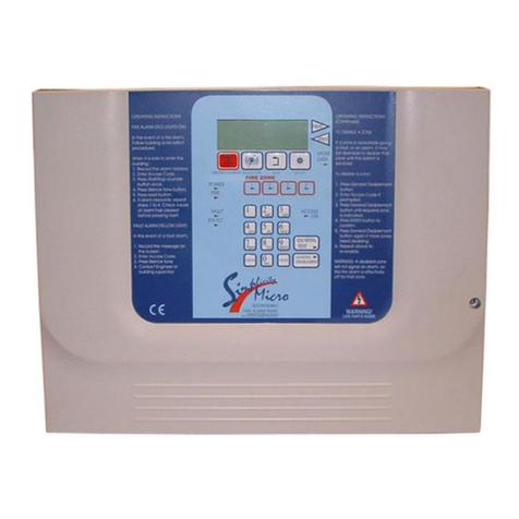
ALL-FILL B-SV-600 User manual

A.F.I. Publication: 1240410
Issue: 1
Date: April 2010
Model B-SV-600
Model B-SV-600
Touch Screen Control Panel
Touch Screen Control Panel
Users Manual
Users Manual
ALL-FILL, Inc.
418 Creamery Way
Exton, PA. 19341 USA
(610) 524-7350 · FAX (610) 524-7346
www.all-fill.com

Title Page
INTRODUCTION.............................................................................................................1
Control Panel....................................................................................................................1
Figure 1 – Model B0SV-600 Filler Control Panel..........................................................1
Control Power Switch.................................................................................................1
Power Indicator ..........................................................................................................1
Reset Switch ..............................................................................................................2
Touch Screen Operation...................................................................................................2
START/STOP................................................................................................................2
MENU SCREENS .........................................................................................................3
Status Messages...........................................................................................................3
Menus & Selections..........................................................................................................4
USING THE CONTROLS ..............................................................................................7
Startup and Initial Operation.............................................................................................7
Test Menu Operations...................................................................................................8
Setting Up Filling ..............................................................................................................9
Picking a Run Program Number...................................................................................9
Setting up Target Weight and Feedback Operation....................................................10
Setting up Auger and Agitator.....................................................................................12
Controlling a Cutoff and Delay After Fill......................................................................13
Specifying Level Control and Product Infeed Operation.............................................14
Starting and Running Filling Production .........................................................................15
Displaying Production Information ..............................................................................16
Production...................................................................................................................16
Production Product Feed Control.............................................................................16
Production Servo Feedback.....................................................................................17
Production A&D Scale Feedback .............................................................................18
Troubleshooting and Service..........................................................................................19
Status Messages.........................................................................................................19
Table 1 – Status Message Troubleshooting .............................................................20
REFERENCE ..................................................................................................................21
System Menus................................................................................................................21
Select Run Program Number......................................................................................21
System Setup .................................................................................................................21
Recycle Control...........................................................................................................21
Reset Production Stats ...............................................................................................22
End of Fill Control .......................................................................................................22
System Configuration .....................................................................................................22
Setup Menus ..................................................................................................................23
Setup Target Weight ...................................................................................................23
Product Name ..........................................................................................................23
Target Weight ...........................................................................................................23
Feedback Control.....................................................................................................23
Feedback Sec./Wt....................................................................................................24
Feedback Samples ..................................................................................................24
Setup Auger and Agitator............................................................................................24
Auger Revolutions....................................................................................................24
Auger Speed ............................................................................................................25
Agitator Control ........................................................................................................25
Agitation Off Delay ...................................................................................................25
Setup Cutoff and Delay After Fill ................................................................................26
Model B-SV-600 Touch Screen Control Panel Users Manual
AFI Publication 1240410
•
Issue: 1
•
April 2010
CONTENTS

Cutoff Control ...........................................................................................................26
Delay After Fill ..........................................................................................................27
Setup Level Control and Product Infeed.....................................................................27
Level Control ............................................................................................................27
Pause Delay.............................................................................................................27
Low Level Agitation ..................................................................................................28
Infeed Control...........................................................................................................28
On/Off Time ..............................................................................................................28
Test Menus .....................................................................................................................29
Test Auger and Agitator...............................................................................................29
Empty Hopper ..........................................................................................................29
Jog Auger .................................................................................................................30
Test Agitator..............................................................................................................30
Test Cutoff, Product Feed & EOF/Run Signal ............................................................31
Test Cutoff ................................................................................................................31
Test EOF Signal .......................................................................................................31
Test Product Feed ....................................................................................................32
Status Indicators.......................................................................................................32
Test Servo and A&D Scale Feedback.........................................................................33
Status Menu....................................................................................................................33
Production ......................................................................................................................34
Production Product Feed Control ...............................................................................34
Production Servo Feedback .......................................................................................34
Production A&D Scale Feedback................................................................................34
APPENDIX .....................................................................................................................35
Run Program Worksheet................................................................................................37
Menu & Selection Reference .........................................................................................39
INDEX .............................................................................................................................42
© 2010 All-Fill, Inc.
4/10 · Printed in the U.S.A.
No liability is assumed with respect to the use of any information contained in this publication. While every precaution has been taken in the
preparation of this publication, All-Fill, Inc.assumes no responsibility for errors or omissions nor is any liability assumed for damages resulting
from the use of information contained in this publication. This publication, as well as operational details described herein, are subject to
change without notice.
Model B-SV-600 Touch Screen Control Panel Users Manual
AFI Publication 1240410
•
Issue: 1
•
April 2010

The ALL-FILL Model B-SV-600 Filler provides accurate, reliable, integrated control of filling
from a single touch screen control panel. This section is intended for new or unfamiliar users
of ALL-FILL Touch Screen controls. If you have not had previous experience with these type
controls, you should first read this section to understand the basic concepts and general
operation of the controller. Subsequent sections of this manual can be used to setup and
operate your ALL-FILL Model B-SV-600 Filler.
The Touch Screen Control Panel allows you to control and operate your ALL-FILL filler
directly from the touch screen panel. There’s no need to learn any special computer terms
or complicated programming procedures. All messages are in plain English. The Control
Panel included on your Model B-SV-600 Filler is shown in Figure 1. Controls are described
in the following.
Model B-SV-600 Touch Screen Control Panel Users Manual
1
AFI Publication 1240410
•
Issue: 1
•
April 2010
INTRODUCTION
Control Panel
Figure 1
Model B-SV-600 Filler Control Panel
COM
CPU
PWR
Control Power Switch
On/Off, lighted pushbutton located below the keypad that controls electrical power to the
Touch Screen controls. Using this switch during operation halts the machine in mid-cycle. It
should only be used in emergencies. The Touch Screen control panel draws very little power
when not in production, and turning the controller off at the end of a shift or day may be
potentially more damaging than any savings offered by turning electrical power off.
Power Indicator
A green lamp that lights to indicate that control power is available.

Reset Switch
Pressing the black RESET BUTTON will restore power to the system after an EMERGENCY
STOP situation. It also brings all devices to their “home” position, and prepares the machine
to enter “run” mode.
All major machine setup, production, and testing are performed using the Touch Screen
panel on the Control Panel. This screen provides simple, direct selection of all operations,
control settings, and production data display. This section provides a description of the dif-
ferent screens and selections available, as well as a sample exercise to practice using the
controls.
START/STOP
Model B-SV-600 Touch Screen Control Panel Users Manual
2
AFI Publication 1240410
•
Issue: 1
•
April 2010
Touch Screen
Operation
Selects operating mode of the equipment. Pressing START initiates a fill cycle. STOP halts
the sequence. PAUSE momentarily halts filling, SINGLE CYCLE allows only a single con-
tainer to index, filled, and leave. EXIT allows access to other menus and screens.

MENU SCREENS
Model B-SV-600 Touch Screen Control Panel Users Manual
3
AFI Publication 1240410
•
Issue: 1
•
April 2010
Provides access to other menus and screens, including:
SYSTEM MENUS Provides access to selections to choose the Setup
Program to use, and to display configuration data.
SETUP MENUS Provides access to selections that define how filling
is performed.
TEST MENUS Provides access to selections that allow individual
operation of equipment and components for testing,
troubleshooting, and adjustment.
STATUS MENUS Provides access to selections about production and
statistical data.
PRODUCTION Provides access to displays and settings to allow
“fine-tuning” during production.
EXIT Leaves the Menu Screens menu.
Status Messages
A single line message indicating the current operational state of the filler. The following mes-
sages may appear:
E-STOP SWITCH WAITING FOR
IS ACTIVATED RECYCLE TIME
SYSTEM READY LOW LEVEL PAUSE
PRESS START BUTTON WAIT FOR PRODUCT
PRESS INITATION SW. OPERATOR PAUSE
TO DISPENSE PRODUCT CHECK PAUSE BUTTON

CUTOFF IS OPEN WAIT FOR INITIATION OR
CHECK SWITCH OR DELAY FOOT SWITCH
AUGER IS TURNING RELEASE INITIATION OR
DISPENSING PRODUCT FOOT SWITCH
DELAY AFTER FILL AC INVERTER
POWER UP DELAY
CLOSING CUTOFF SERVO DRIVE
CHECK CLOSING TIME NOT READY
SYSTEM IS RUNNING
A series of interactive, English-language menus and selections provide operational control
of the filler. Each menu has an associated group of selections in that general category to
allow you to select and specify control in an organized, logical manner. Selections in each
menu allow you to enter values from a given range, such as Target Weight; or make a
choice between different functions, such as agitate during filling, agitate continuously, or turn
agitation off. Individual descriptions of each Menu Selection are provided in the REFER-
ENCE section of the publication. The following describes each Menu in general.
System Menu
The System Menu provides selections to choose what Setup Program to use for produc-
tion, and to display service-related configuration information. Menu includes:
● Select Run Program Number
● System Setup
Recycle Time
Recycle Control
Reset Production Stats
End of Fill Control
● System Configuration
Setup Menu
The Setup Menu contains selections that let you choose filling operations (such as fill
amount, agitation control, cutoff control, etc.) at the machine. Selections made in the Setup
Menu are saved together as a numbered Run Program stored in memory of the control
panel. Selections include:
● Setup Target Weight
Product Name
Target Weight
Feedback Control
Feedback Sec./Wt.
Feedback Samples
● Setup Auger and Agitator
Auger Revolutions
Model B-SV-600 Touch Screen Control Panel Users Manual
4
AFI Publication 1240410
•
Issue: 1
•
April 2010
Menus & Selections

Auger Speed
Agitation Control
Agitation Speed
Agitation Off Delay
● Setup Cutoff and Delay After Fill
Cutoff Control
Open Time
Close Time
Delay After Fill
● Setup Level Control and Product Infeed
Level Control
Pause Delay
Low Level Agitation
Infeed Control
Off Time
On Time
Test Menu
The Test Menu allows you to individually operate machine equipment when not currently in
production. These selections can be used to perform maintenance or adjustments on the
machine. Test Menu includes:
● Test Auger and Agitator
Empty Hopper
Jog Auger
Test Agitator
Jog Rev.
Auger Speed
Agitator Speed Option
● Test Cutoff, Product Feed & EOF/Run Signal
Test Cutoff
Test EOF Signal
Test Prod. Feed
Cutoff Switch
Level Control
Initiation Switch
Agit. Run
C/W Raise
C/W Lower
E-Stop Switch
● Test Servo and A&D Scale Feedback
Weight
A&D Scale String
A&D Scale Setup
C/W Raise/Lower
Status Menu
The Status Menu lets you see filling production values and amounts while the machine is
running. Although you can’t change values in this menu, you can display them to later adjust
your setup program, filling accessories, etc. Status selections include:
Model B-SV-600 Touch Screen Control Panel Users Manual
5
AFI Publication 1240410
•
Issue: 1
•
April 2010

● Auger Rev.
● Setup Auger Revolutions Adjustment
● Setup Auger Speed Adjustment
● CPM
● Auger Speed
● Setup Auger Revolutions Adjustment
● Setup Auger Speed Adjustment
● Auger
● Agitator
● Cutoff
● Infeed
● EOF Signal
● Production Counts
● Low Level Pause Counts
● Low Level
● Cutoff Switch
● Initiation
● E-Stop
Production
The Production menu provides a quick and easy method of accessing setup selections and
settings that may require adjustment or “tuning” while in filling production. Included are:
● Production Product Feed Control
Low Level Control
Low Level Agitation
Pause Delay
Low Level Pause Count Display
Low Level Status
Agitation Status
Infeed Status
Infeed Control
On/Off Time
● Production Servo Feedback
Target Weight
Feedback Rate
Feedback Control
Feedback Weight Display
Auger Revolution Display
C/W Raise/Lower Status
● Production A&D Scale Feedback
Avg. Scale Weight Display
Auger Revolution Display
Sample Counts Display
Target Weight
Feedback Samples
Feeedback Control
Last Scale Weight Display
Hi/Lo Limit Display
Model B-SV-600 Touch Screen Control Panel Users Manual
6
AFI Publication 1240410
•
Issue: 1
•
April 2010

After becoming familiar with the operating controls and displays (see “INTRODUCTION”),
you can use this section to learn how to setup and run the filler from the control panel.
Installation of the machine is described separately and contained in the documentation
package accompanying your order.
It is recommended that all installation and connections be completed before attempting any
of the setup, calibration or production procedures contained in the following.
After installing the filler and connecting the required electrical and pneumatic inputs, the
machine can be started and initially operated to ensure that all components are functioning
correctly. After electrical power is turned-on, the following screen appears on the touch
screen panel.
Model B-SV-600 Touch Screen Control Panel Users Manual
7
AFI Publication 1240410
•
Issue: 1
•
April 2010
USING THE
CONTROLS
Startup and Initial
Operation
You can use this screen to verify and record:
•Model Designation
•Wiring Diagram
•Human/Machine Interface (HMI) touch screen panel Version
•Programmable Logic Controller (PLC) Version
After recording this information, use the Control Power switch on the panel. The Main Status
screen should appear.

Test Menu Operations
The Test Menu provides selections to individually operate and test various components and
devices of the machine. You can use the following to test these devices prior to any setup or
operation.
1. Press STOP from the START/STOP menu. Test functions can only be accessed when
machine is stopped.
2. Press MENU SCREENS and press TEST MENUS. Press EXIT.
3. Select the following screens from the Test Menu:
•Test Auger and Agitator
•Test Cutoff, Product Feed & EOF/Run Signal
•Test Servo and A&D Scale Feedback
4. When selected, use switch icon graphics to turn equipment on & off or verify the on/off
status of limit switches, contacts, etc. Make required adjustments as needed.
Upon successful completion of this testing, you can proceed to the following to start setting
up the filling controls.
Model B-SV-600 Touch Screen Control Panel Users Manual
8
AFI Publication 1240410
•
Issue: 1
•
April 2010

Setup of the filler component consists of the following major procedures:
•Picking a Run Program number.
•Setting up Target Weight and Feedback Operation
•Setting up Auger and Agitator
•Controlling a Cutoff and Delay After Fill
•Specifying Level Control and Product Infeed Operation
Procedures to perform these setup operations are provided in the following. The Appendix
of this manual contains a Setup Run Program Worksheet that can be used to help you
develop and record Setup selections and entries.
Picking a Run Program Number
The Touch Screen controls provide the ability to store up to 50 different setup run programs
for use with different containers, products, fill amounts, etc. Use the following to set up and
store setup programs.
Model B-SV-600 Touch Screen Control Panel Users Manual
9
AFI Publication 1240410
•
Issue: 1
•
April 2010
Setting Up Filling
•Press MENU SCREENS and SYSTEM MENUS. Press EXIT.
•From the SYSTEM MENU screen, Press SELECT RUN PROGRAM NUM-
BER to choose a number. Press the corresponding number from 1-5 or use the è
to choose from 6-50.

Setting up Target Weight and Feedback Operation
The Setup Target Weight screen provides access to selections to define product name, tar-
get filling weight, and filling amount feedback operation. Use the following procedure to
specify these settings in your Run Program.
1. Press MENU SCREENS and SETUP MENUS. Press EXIT. The SETUP TAR-
GET WEIGHT screen should appear. If not, use è/çuntil the Setup Target Weight
screen appears.
Model B-SV-600 Touch Screen Control Panel Users Manual
10
AFI Publication 1240410
•
Issue: 1
•
April 2010
2. Press PRODUCT NAME to associate a container, product, or batch with a particular
Run Program. Any alphanumeric character (0-9/A-Z) can be used, at up to 10 charac-
ters in length.
3. The total amount of material to be dispensed during filling is defined with the TARGET
WEIGHT selection. You should enter the desired, final, filled weight. Feedback control
selections (see following) use this Target Weight value for feedback calculation and cor-
rection.
4. Press FEEDBACK CONTROL to select the type of feedback used for correction of fill
weights. The following selections are available:
Servo – Defines a raise/lower signal used as feedback to the filler. Typically, servo
raise/lower signals are provided by a checkweigher. When selected as “Servo” the
Feedback Sec./Wt. selection is used to specify how fill weights are corrected (see Step
5).
A&D Scale – Defines a scale to provide feedback correction to the filler. When selected
as “A&D Scale” the Feedback Samples selection is used to specify how fill weights are
corrected (see Step 6).
None – Feedback not used.
5. If Feedback selected as “Servo” the FEEDBACK SEC/WT selection defines the
amount of time that is required to change auger revolutions based on weight value. This
value should match the same value on the weighing equipment.

6. If Feedback selected as “A&D Scale” the FEEDBACK SAMPLES entry selects the
total amount of weight sampling data collected at the A&D Scale during weighing used
in calculation of feedback adjustment. Generally, greater sampling may achieve greater
accuracy, however adjustment may require several fill cycles to complete.
7. Proceed to the following to continue setup of auger revolutions and agitator operation.
Model B-SV-600 Touch Screen Control Panel Users Manual
11
AFI Publication 1240410
•
Issue: 1
•
April 2010

Setting up Auger and Agitator
The Setup Auger and Agitator screen provides access to selections to select how many
auger revolutions are performed during a fill cycle and operation of the agitator drive within
the hopper of the filler. Use the following procedure to setup auger revolutions and agitator
operation in your Run Program.
1. Press MENU SCREENS and SETUP MENUS. Press EXIT. Use èuntil SETUP
AUGER AND AGITATOR screen appears.
Model B-SV-600 Touch Screen Control Panel Users Manual
12
AFI Publication 1240410
•
Issue: 1
•
April 2010
2. The AUGER REVOLUTIONS selection defines the amount of product dispensed dur-
ing a fill cycle. The amount of product dispensed per revolution is a function of the auger
(or pump) size as well as physical characteristics of the product (i.e., density).
!!! IMPORTANT !!!
DO NOT enter a value less than one-half (0.5) a revolution.
3. Press AUGER SPEED to select the desired operating speed of the servo fill motor.
Speed settings will vary according to amount of fill, desired accuracy levels, as well as
production rates. Use numeric keypad for desired rpm and press ENT.
4. The on/off control and duration of product agitation can be controlled with the AGITA-
TOR CONTROL selection. Selections are available for continuous agitation, agitation
during filling only, and no agitation. Operation of slow speed agitation will depend on
product type, environmental factors, and specific product characteristics.
5. Press the area adjacent to Agitation Control to select agitation speed. Product agitation
should generally match auger speed. If faster auger speed is selected, product agitation
should be selected at a faster setting.
6. Press AGITATION OFF DELAY to momentarily delay turning agitation off to accom-
modate high cycle rates and operation with other equipment.
7. When entries are complete, record settings on the Run Program Worksheet (see
“Appendix”) and press the èto continue.

Controlling a Cutoff and Delay After Fill
The Setup Cutoff and Delay After Fill screen provides access to selections to control a cutoff
device (if used), and select a variable delay to occur after a fill cycle. A delay after fill can be
used to coordinate operation of the auger filler with other equipment, or to allow product to
settle and distribute into a container. Use the following procedure to control a cutoff device
and select a Delay After Fill in your Run Program.
1. Press MENU SCREENS and SETUP MENUS. Press EXIT. Use èuntil SETUP
CUTOFF AND DELAY AFTER FILL appears.
Model B-SV-600 Touch Screen Control Panel Users Manual
13
AFI Publication 1240410
•
Issue: 1
•
April 2010
2. Product cutoff devices that can be installed at the funnel of the filler can be controlled
using the CUTOFF CONTROL selection. Types of cutoff devices used will vary with
design, product characteristics, and other accessories used at the filler. The following
types of cutoff control are available.
None – No Cutoff control required.
By Time – Specifies a period of time for the cutoff to open and close. The actual time is
specified in the OPEN TIME and CLOSE TIME entries.
Limit Switch – Specifies a period of time to delay the closing of the cutoff. The limit
switch determines cutoff opening and filling. The opening time is not selectable in this
mode.
Open Time – Specifies the amount of time that it takes to fully open the cutoff, prior to
the start of the fill. Entries can be made in this window only if cutoff control has been
selected as “Time.”
Close Time – Specifies the amount of time (delay) that it takes to fully close the cutoff,
after the fill is completed, can be specified. Entries can be made in this window when
cutoff control has been selected as either “Time” or “Limit Switch.”
3. Press DELAY AFTER FILL to coordinate operation of the auger filler with other
equipment, or to allow product to settle and distribute into a container.
4. When entries are complete, record settings on the Run Program Worksheet (see
“Appendix”) and press the èto continue.

Specifying Level Control and Product Infeed Operation
These setup screens specify how the filler hopper is re-supplied with product from (external)
infeed equipment. The following selections are available.
Model B-SV-600 Touch Screen Control Panel Users Manual
14
AFI Publication 1240410
•
Issue: 1
•
April 2010
1. Use LEVEL CONTROL to specify operation of the Level Control switch installed in the
hopper cover at the filler. It can be selected as “On” or “Off.” When entered as “On” a
signal is generated indicating a low level condition exists. When selected as “On,” the
Pause Delay and Low Level Agitation selections (see following) can be further used to
specify low level control.
2. The PAUSE DELAY key provides a delay to occur between detection of a low level
condition in the hopper and a system pause. This selection can be used to allow infeed
equipment to deliver product to the hopper without excessive “pausing” of production.
3. The LOW LEVEL AGITATION key allows the product agitator blade in the hopper to
operate at low product levels to ensure that product is fed into flights of the auger before
re-supply occurs. When selected as “On,” slow speed agitation operates despite the set-
ting in the “Auger and Agitation“ setup menu.
4. INFEED CONTROL selects the type of signal used to actuate external product infeed
equipment. Selections are available for Pulse, Continuous, or None. When selected as
“Pulse,” pulse width can be defined using the On/Off Time entries. Infeed Control entries
will depend upon the type and wiring of external product infeed equipment used. You
may need to refer to wiring information of this external equipment to determine the cor-
rect entry.
5. The ON/OFF TIME selection specifies pulse width of external equipment used for
product re-supply.
6. When entries are complete, record settings on the Run Program Worksheet (see
“Appendix”).

Use the following as a guideline for starting and running filling production with the B-SV-600
using the touch screen Control Panel.
1. Verify that hopper contains sufficient product and that empty containers are available.
2. Clear any accumulated product or debris.
3. Turn power on at the Control Panel.
4. Press SYSTEM MENUS to choose which Setup Program to use and other System
Setup entries.
5. After selecting the Run Program number, press for other System Setup entries. Press
SYSTEM SETUP for recycling control and times, reset any accumulated production
count statistical totals, and define the End Of Fill (EOF) signal for external equipment.
Model B-SV-600 Touch Screen Control Panel Users Manual
15
AFI Publication 1240410
•
Issue: 1
•
April 2010
Starting and Running
Filling Production
6. Press START on the Main screen and verify system operation from the Status
Messages appearing at the top of the Main screen. Status messages are described
elsewhere in this manual.

Displaying Production Information
The Status Menu screens provide complete summaries of all relevant filling production totals
while in operation. These screens are available from the STATUS MENUS Menu Control
key.
Production
The screens available from the Production Menu provide a quick and easy method of
accessing setup selections and settings that may require adjustment or “tuning” while in fill-
ing production. The following can be selected and displayed from this Menu Screen selec-
tion.
Production Product Feed Control
Model B-SV-600 Touch Screen Control Panel Users Manual
16
AFI Publication 1240410
•
Issue: 1
•
April 2010
Displays:
Low Level Pause Count
Low Level
Agitator
Infeed
Settings:
Low Level Control
Low Level Agitation
Pause Delay
Infeed Control
Off Time
On Time

Production Servo Feedback
Model B-SV-600 Touch Screen Control Panel Users Manual
17
AFI Publication 1240410
•
Issue: 1
•
April 2010
Displays:
C/W Raise/Lower
Feedback Weight
Auger Revolutions
Settings:
Target Weight
Feedback Rate
Feedback Control
Table of contents
Other ALL-FILL Control Panel manuals
