Allaway Manta 3000 Technical manual

ALLAWAY MANTA
CENTRAL VACUUM CLEANING SYSTEM
PLANNING AND INSTALLATION
MANUAL

2
We reserve the right to make changes.
1. Usages................................................................................................................................................. 3
2. Legislation and regulations............................................................................................................... 3
3. The Manta central vacuum cleaning system ................................................................................... 3
3.1. System for one user......................................................................................................................3
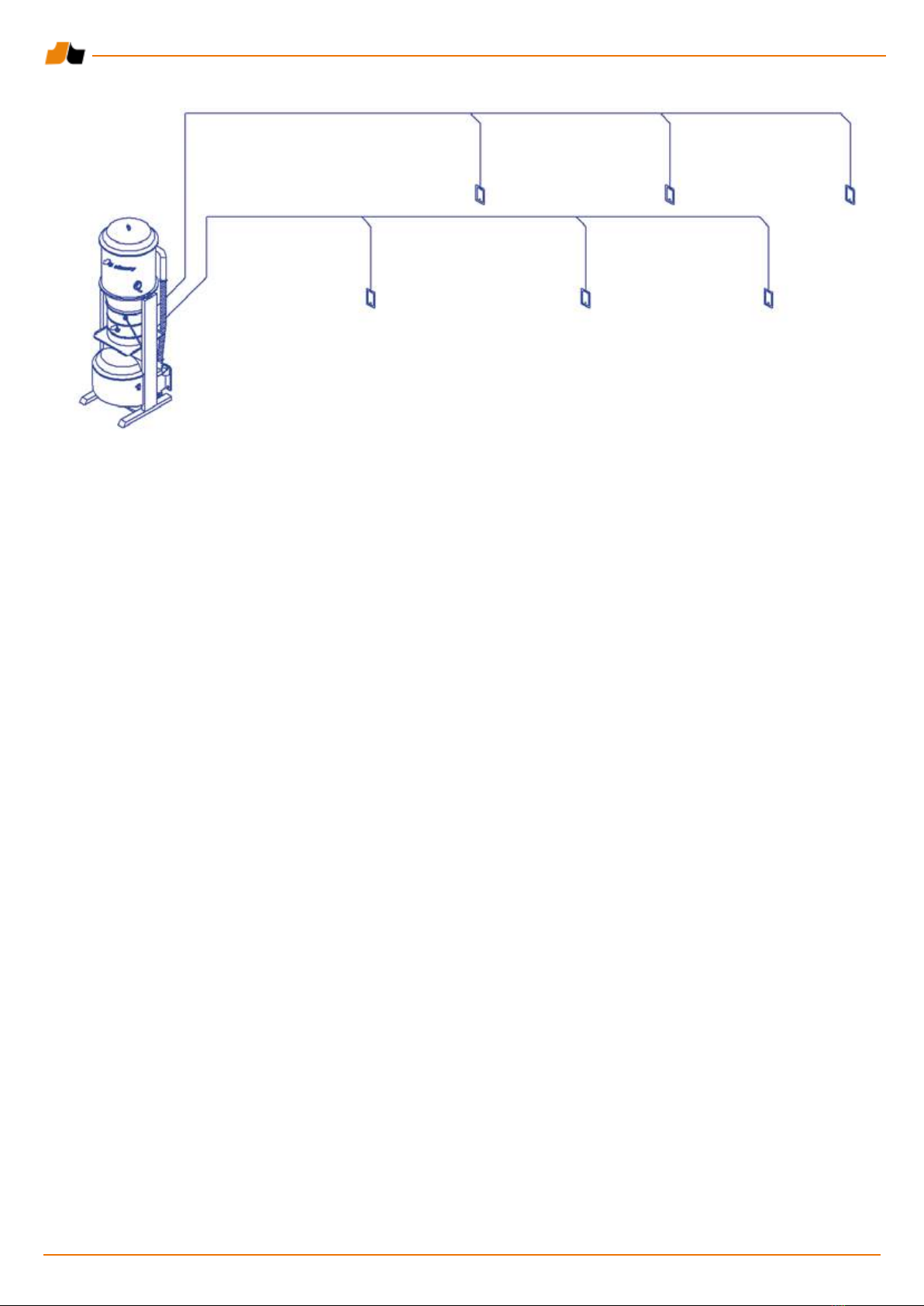
3.2. System for several users .............................................................................................................. 4
4. Technical information for the central units...................................................................................... 6
5. Selecting the central unit................................................................................................................... 7
6. Location of the central unit ............................................................................................................... 8
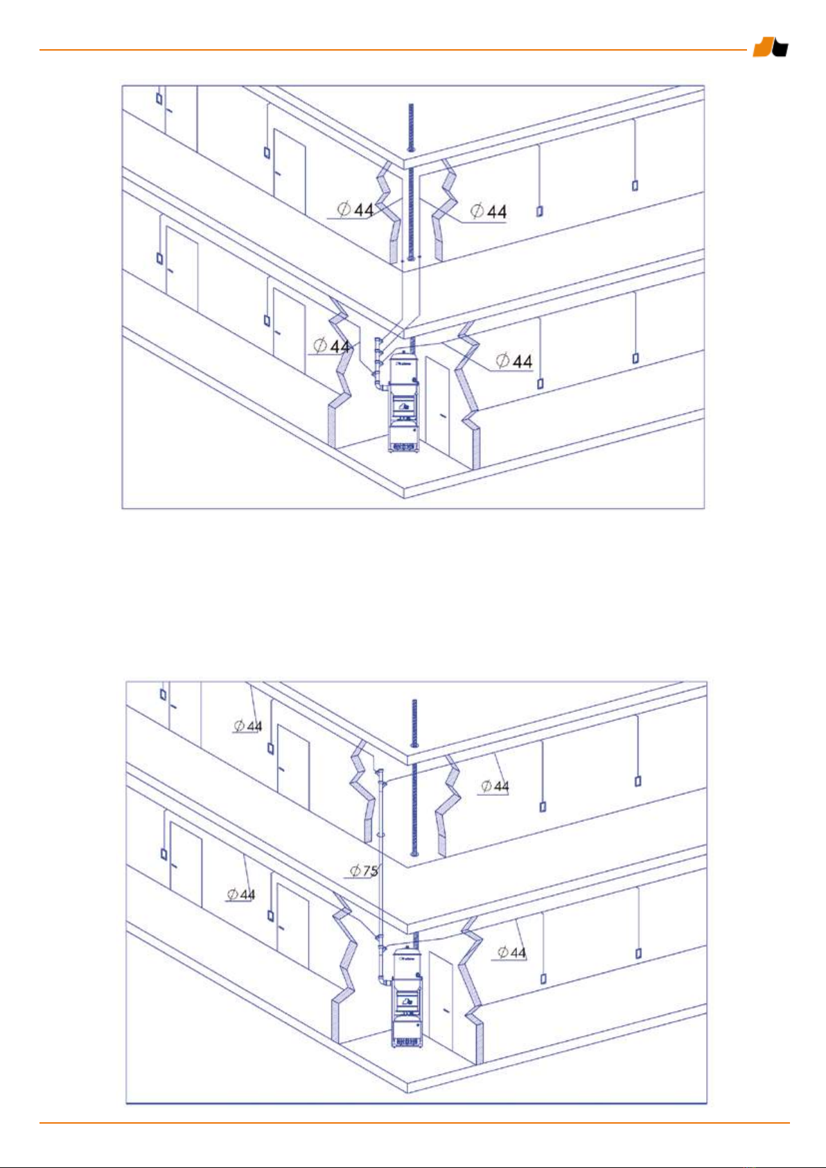
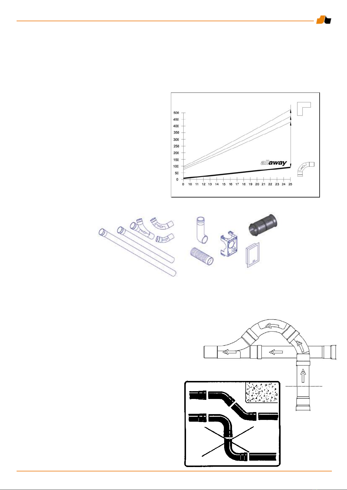
6.1. Length of the dust piping ..............................................................................................................8
6.2. Requirements for the location of the central unit .......................................................................... 8
6.3. Maintenance operations on the central unit.................................................................................. 8
6.4. Ventilation of the location of the central unit ................................................................................. 8
7. Dust piping.......................................................................................................................................... 9
7.1. Features of the dust pipes ............................................................................................................ 9
7.2. Parts of the dust piping ................................................................................................................. 9
8. Installing the dust piping................................................................................................................... 9
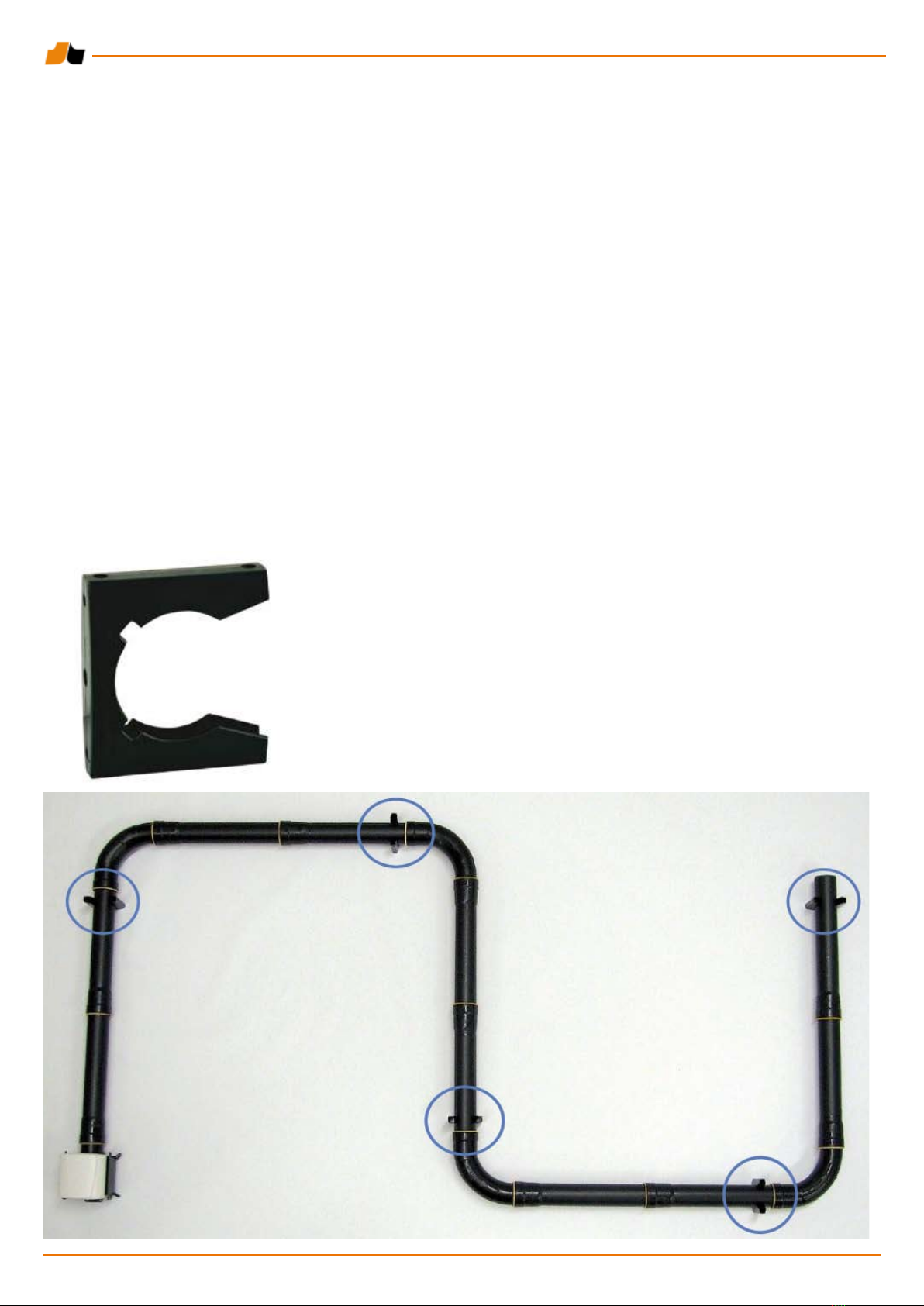
8.1. Attaching the pipes .......................................................................................................................9
8.2. Supporting .................................................................................................................................. 10
8.3. Hung ceiling ............................................................................................................................... 11
8.4. Cast oor ................................................................................................................................... 11
8.5. Hollow core slab ........................................................................................................................ 11
8.6. Other solutions ........................................................................................................................... 11
8.7. Leadthroughs in compartmentation structures .......................................................................... 11
8.8. Leadthrough to the air-raid shelter.............................................................................................. 11
8.9. Expansion joint ........................................................................................................................... 11
9. Chanelling the exhaust air............................................................................................................... 12
10. Installing the wall inlets ................................................................................................................. 12
10.1. Installation frequency and height .............................................................................................. 13
10.2. Installation locations of the wall inlets....................................................................................... 13
10.3. Wall inlet models....................................................................................................................... 13
10.4. Installing the wall inlet to a slab wall using a mounting plate.................................................... 14
10.5. Beam thickness in ush mounting ............................................................................................ 15
10.6. Installing a wall inlet on cast walls or oors .............................................................................. 16
10.7. Installing the wall inlets to brick walls ....................................................................................... 16
10.8. Surface mounting of wall inlets ................................................................................................. 17
10.9. Shortening the coupling muff for the wall inlet .......................................................................... 17
11. Starting circuit and turning on the system .................................................................................. 17
12. Connecting the central unit to the dust piping............................................................................ 18
13. Testing the system ......................................................................................................................... 18
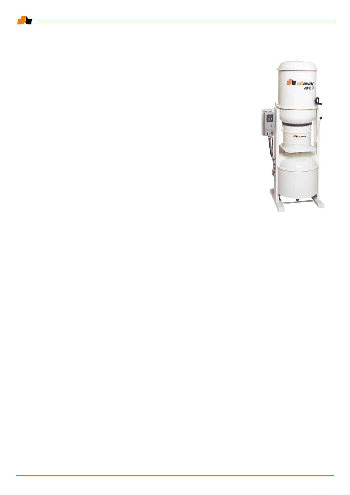
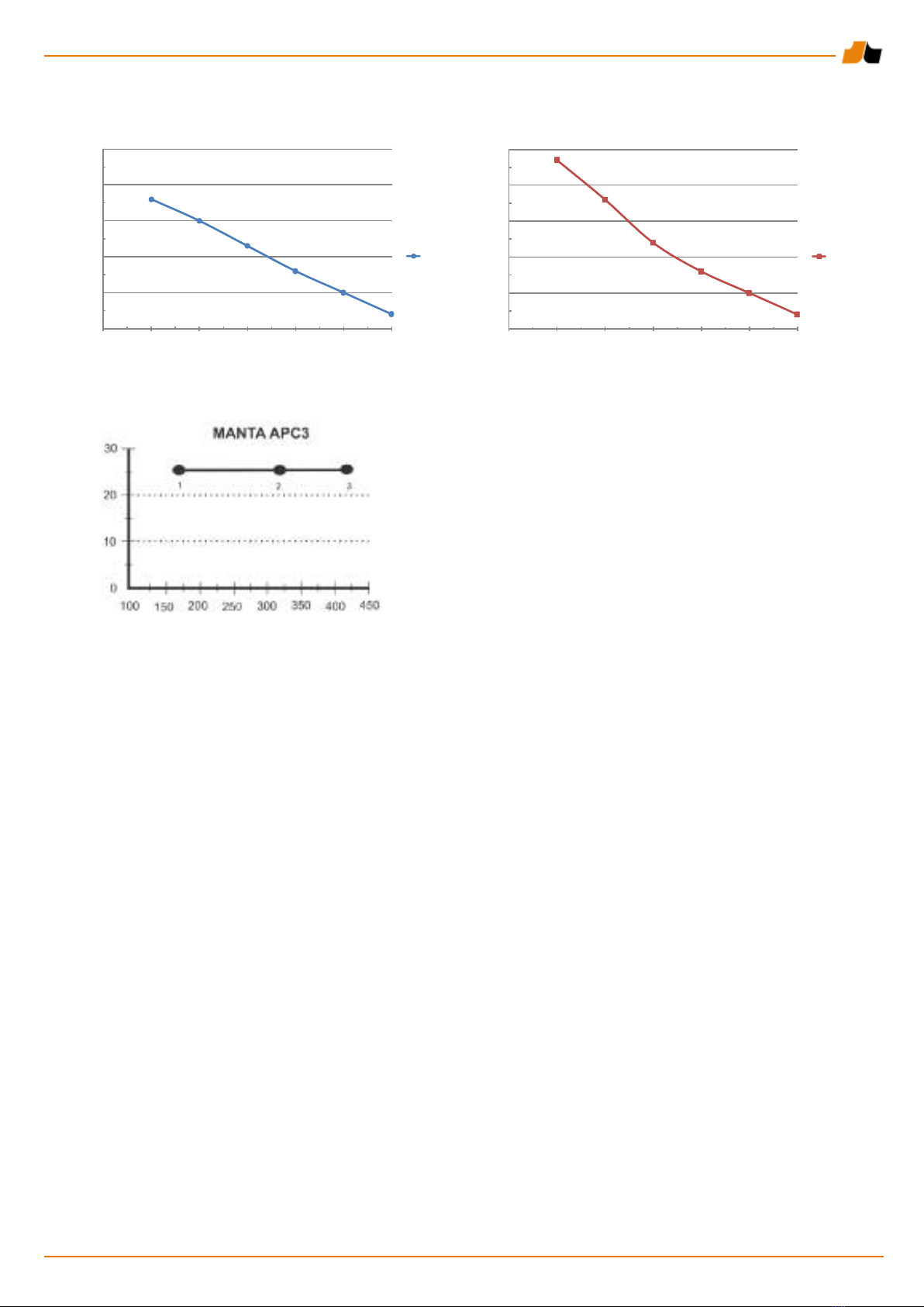
14. The Manta APC 3 central unit........................................................................................................ 19
14.1. The automatic power control in the Manta APC 3 central unit ................................................. 19
14.2. Preset rotation speeds.............................................................................................................. 19
15. Model of the work specication for the central vacuum cleaning system ............................... 20
Contents

3
3.1. System for one user
For systems for one user, lead the piping from the wall inlets to the central unit using the shortest possible route. The
wall inlets can be branched from one Ø 44 mm pipe. One suction pipe leading to the central unit and one exhaust air
duct leading outside are enough.
1. Usages
The Allaway Manta central vacuum cleaning system is intended for professional usage in places where large areas
need to be cleaned, with equipment that is used for longer periods than normal domestic use, and where the systems
have several simultaneous users. Typical usages include hotels, ofces, sheltered homes, passenger ships, daycare
centres, and schools. The Allaway Manta central vacuum cleaning system is also often used in libraries, theatres and
concert houses, and other public buildings. Industrial applications include ofces and other such spaces.
The Allaway Manta central vacuum cleaning system cannot be used in industrial production facilities where the
amount of dust and rubbish being cleaned is large, or the pieces being cleaned are large and heavy, such as chippings
from machine tools, pieces of metal thread, or oily pieces. The Manta system is also not suitable for places where the
objects to be vacuumed differ from normal household dust and rubbish, or for local extraction of welding ue gases,
soldering, etc.
Only durable wall-inlet-started cleaning equipment with steel handle pipes and telescopic wands may be used in the
Allaway Manta central vacuum cleaning system. Due to the control technology used in the Manta system, handle-
started cleaning equipment may not be used.
2. Legislation and regulations
There are no comprehensive re safety regulations or instructions for central vacuum cleaning systems. The construction
instructions and regulations for the installation country and the general quality requirements for HPAC construction
must be applied in the planning and installation of the system.
The heat insulation and airtightness of the exhaust air duct must be sufcient. This is the case when using sheet
metal ducts. In addition, the integration to any necessary protective appliances, such as re shutoff valves, must be
accounted for in the selection of the exhaust air duct. The locations of the exhaust holes are determined according to
the applicable construction regulations.
The noise level of the central unit must be considered when selecting its location.
TheAllaway suction piping is made of environmentally friendly recyclable plastic material (PP or PVC). The suction piping
is usually made using Allaway dust pipes, but other pipes may be used for special installation sites. The regulations
and instructions for plastic drains are applied for the leadthroughs in compartmentation doors.
3. The Manta central vacuum cleaning system

4
3.2. System for several users
Two basic points are used as the basis for the planning:
1) The amount of air vacuumed simultaneously by two users does not t to one Ø 44 mm dust pipe.
2) If larger pipes were used for the dust piping, the ow rate would be insufcient with only one user.
If the spaces to be cleaned are divided into cleaning areas according to the requirements of the usage situations, this
will guarantee a sufcient ow rate in the dust piping in all usage situations. Expensive and noisy by-pass systems
are not needed, and the central vacuum cleaning system is energy-efcient.
Cleaning areas can include the various parts or oors of the building. In hotels, the rooms can be divided into cleaning
areas of the same size based on the number of rooms or the side of the corridor that they are on. Only one user can
work on one cleaning area at any one time. A layout of the division of the cleaning areas must be made for the users
in systems with several users. Locate the layout in a visible place, such as next to the hose holder.

5
In buildings with several oors, the Ø 75 mm collector pipe of the central unit can be led vertically through the oors,
or the Ø 44 mm dust pipes from the cleaning areas can be joined on their respective oors. This requires the location
of the central unit to be directly below the collector pipe. The collector pipe must never under any circumstances be
designed to be horizontal. The largest angle allowed for the collector pipe is 45°.
The most important issue when planning a system for several users is to lead a separate Ø 44 mm dust pipe from
the cleaning area to the central unit. The pipes from the various cleaning areas must not under any circumstances be
connected before the Ø 75 mm central unit collector pipe.

6
4. Technical information for the central units
The temperature of the motor or turbine may rise to almost 80SDgrC. The turbine is
equipped with thermal protection at 80SDgrC, at which temperature the protection will
turn off the device.
Allaway Manta 3000
The Manta 3000 central unit is designed for one user with the maximum distance of
70 metres between a wall inlet and central unit.
Allaway Manta 6000
The Manta 6000 central unit is designed for two simultaneous users with the maximum
distance of 60 metres between a wall inlet and the central unit. It is intended for one user
per cleaning area.
The system for two simultaneous users also requires the piping to be divided into at least
two separate cleaning areas. If used for one user only, the maximum distance between a
wall inlet and the central unit is 100 metres.
Allaway Manta APC 3
The power of the Manta APC 3 central unit can be adjusted. It is intended for 1-3
simultaneous users. The Automatic Power Control (APC ) considers the number of users
in the system and ensures sufcient suction power, while saving energy if only one or two
users are using the system.
The system for three simultaneous users also requires the piping to be divided into at least
three separate cleaning areas. The maximum suction distance for three users is 60 metres
per user, 70 metres each for two users, and 80 metres for one user. The maximum suction
distance for one user is 100 metres when using the xed Preset frequency setting. The
collector pipe is not considered in the suction distance.
Manta 3000 Manta 6000 Manta APC 3
Rated power 4.0 kW 5.5 kW 4.0-7.5 kW
Electrical connection 32 A 3-phase 32 A 3-phase 16 A 3-phase
coupler plug installation/ coupler plug installation/ coupler plug installation/
with 25 A front fuses with 25 A front fuses with 16 A front fuses
Drip-proof casing class IP34 IP34 IP34
Turbine thermal protection
80 C Yes Yes Yes
Measured from the turbine:
- Maximum amount of air 108 l/sec. (390 m³/h) 108 l/sec. (390 m³/h) 178 l/sec. (640 m³/h)
- Maximum low pressure approx. 32 kPa approx. 40 kPa 33 kPa
Noise level of the machine
Lp +-2 dB (A) * approx. 70 dB(A) approx. 69 dB(A) approx. 75 dB(A)
Dust canister 34 litres 34 litres 34 litres
Suction hose (Ø 32 mm),
length 8 or 10 metres 8 or 10 metres 8 or 10 metres
Height 1965 mm 1965 mm 1965 mm
Width 600 mm 600 mm 800 mm
Depth 650 mm 650 mm 650 mm
Weight 149 kg 153 kg 155 kg
Maximum suction distance
(Excl. the collector pipe)
Autom. Fixed
- 1 user 70 metres 100 metres 80 metres 100 m
- 2 users - 60 metres 70 metres 80 m
- 3 users - - 60 metres -
* Measured in an anechoic room, from a distance of 1 metre, directly in front, with the cleaning equipment attached
to the wall inlet.

7
Fan diagrams for the central units
The air quantities and low pressures for the Manta 3000 and Manta 6000 central units are measured at the turbine.
The air quantities and low pressures for the Manta APC3 are measured at the central unit with one, two, and three
users.
5. Selecting the central unit
Example:
- The oor area to be cleaned is 5,800 m²
- The time in use is 8 hours
- 6 simultaneous users are needed
Solutions:
1) 2 Manta APC 3 central units, if the structure of the building and the location of the central unit are such that the
maximum distance between the furthest wall inlet and the central unit is 60 metres, and that there can be three
simultaneous users per central unit.
2) 3 Manta 6000 central units, if the maximum distance from the furthest wall inlet is 60 metres. The central units can
be located on different sides of the building. There can be two simultaneous users per central unit.
3) 6 Manta 3000 central units, if the maximum distance from the furthest wall inlets is 70 metres.
0
10
20
30
40
50
060 120 180 240 300 360
Alipaine kPa
Ilmamäärä m3/h
MANTA 6000
MANTA 6000
0
10
20
30
40
50
060 120 180 240 300 360
Alipaine kPa
Ilmamäärä m3/h
MANTA 3000
MANTA 3000
Low pressure kPa
Low pressure kPa
Air quantity m³/h Air quantity m³/h
Low pressure kPa
Air quantity m³/h
Number of users

8
6. Location of the central unit
Several factors affect the location of the central unit. The following section
discusses the situation for one central unit. The same principles can be
applied for solutions with several central units, if the total area to be cleaned
is divided into separate areas for each central unit. At least the following
issues must be considered when planning the system:
6.1. Length of the dust piping
The distance from the furthest wall inlet to the central unit must be within
the limits dened for each central unit. If at all possible, locate the central
units close to the centre of the area being cleaned, in order to regulate the
length of the dust piping. In addition to cost savings, a shorter dust piping
willl also achieve improved cleaning efciency.
6.2. Requirements for the location of the central unit
The central unit should not usually be attached to a oor, and under no
circumstances to a wall. There should be approximately 1 metre free space
in front of each central unit for maintenance purposes. Several central
units may be installed in the same space next to each other. Also reserve
space for the functional diagrams of the system and the operating and
maintenance instructions. The central unit is usually located on the ground
oor or a cellar, but it can just as well be located one oor higher than the
area to be cleaned. However, the maximum rise in the piping must not
exceed 6 metres.
The central unit must be located in a space where the exhaust air duct can
be led out. The temperature of the installation space of the central unit must
not be under +5°C or over +40°C.
The noise level from the central units is between 65 and 75 dB (A), which
must be considered in the surrounding wall structures The turbine does not
cause structure-borne noise that carries in the structure of the building, as
it rests on rubber legs.
6.3. Maintenance operations on the central unit
Locate the central unit in a space where it can be easily accessed
for maintenance. Good locations include cleaning rooms and storage
facilities in central locations. Avoid distant locations that are not easily
accessed, because this may cause the emptying of the dust canister to
be considered unpleasant, and to be left undone.
6.4. Ventilation of the location of the central unit
Part of the power of the central unit is transformed into heat. Most of the
heat is transferred outside with the exhaust air, but some of it will remain in
the installation space of the central unit when the vacuum cleaner is used.
The central unit produces heat in the installation space as follows:
Manta 3000 500–800 W
Manta 6000 800–1,500 W
Manta APC 3 600–1,500 W
The heat load greatly depends on the surface materials of the cleaned areas.
As an example, cleaning tted carpets produces more heat than cleaning
hard oor surfaces. The ambient temperature of the electric motor of the
central unit must not exceed 40°C, which is why the excess heat must be
removed from the space in question.
The amount of air to be exhausted depends on the length of the period of
use, the size of the installation space, and the wall materials. The general
guideline is that the need for ventilation in spaces of less than 20 cubic
metres is approximately 55-70 l/s per central unit. If this cannot be arranged
through the general ventilation system of the building, for example a
thermostat-operated exhaust fans can be used.
Exhaust air duct
Installation location
ventilation air
Replacement air

9
7.2. Parts of the dust piping
The following factory-made parts are available
for the installation of the dust piping:
Dust pipe 0.6 m, Ø 44 mm
Dust pipe 1.2 m, Ø 44 mm
Dust pipe 2.4 m, Ø 44 mm
Branch 45°, Ø 44 mm
Elbow 15°, Ø 44 mm
Elbow 45°, Ø 44 mm
Elbow 90°, Ø 44 mm
Wall inlet and supplies
Connector
The diameter of the dust pipes in the Allaway Manta
system is 44 mm. With a smaller diameter, the loss of
pressure caused by the ow resistance would be too
great, causing decreased cleaning power. With a larger
diameter, such as 50 mm, the ow rate of air in the piping
would be too small, and the ow of heavy rubbish, such
as stones and sand, would be insufcient. The shape of
the bends and the smoothness of the inside surface are
critical for achieving excellent ow properties. The parts of
the Allaway piping that are particularly exposed for wear,
such as the elbow and branch pieces, are strengthened.
The sleeve joints in the Allaway dust pipes are always
adjusted according to the ow direction, minimising the
risk of blockage.
7. Dust piping
7.1. Features of the dust pipes
The design of the dust piping is crucial for the operation of the entire system. The size and ow properties of the
Allaway dust pipes are developed to ensure a ow rate in the piping of at least 20 m/s in normal use. However, this
requires that the equipment-specic maximum line lengths and numbers of users are not exceeded. At a ow rate of
20 m/s, the dust and even any heavier rubbish will be transferred all the way to the dust canister.
The diameter of the dust pipe must be in line with the power of the central unit, cleaning hose, and cleaning equipment.
8. Installing the dust piping
The dust piping can be installed even in narrow spaces, because the diameter of the pipes is only 44 mm (51 mm
in sleeve joints). However, we recommend installation in easy-to-access places, where the risk of damage during
construction and maintenance is minimised. Enter the pipes and low-voltage leads from each cleaning area in the
plan. he piping should be installed as direct and short as possible, avoiding unnecessary bends and corners.
8.1. Attaching the pipes
Ensure that all parts are in good condition both on the inside
and outside, and clean if necessary. Install the yellow locking
seal inside the sleeve. Push the pipe directly into the sleeve,
rotating the pipe slightly, until the end of the pipe is sealed
to the bottom of the sleeve. The pipe is sufciently extended
when the point of connection of the pipes is over the white
marking line. If you cut the pipe, draw the marking line at the
correct point using another marked pipe. The locking seal
ensures and locks the joint. Branches must always join the
body pipe from above or one side. The joints must be situated
in the correct way, ensuring that there are no collision surfaces
in the piping where shards of glass, toothpicks, nails, etc. could
catch. The arrows in the parts of the piping show the direction
of the ow. When installing the piping, the sleeve must always
be on the wall inlet side of each part. On the exhaust side,
the sleeve must be towards the central unit.
Power loss comparison for 90SDgr pipe elbows
Power loss Pa
Allaway's advantage
compared
to others
Speed m/s
ELBOW COUPLING
M O U N T I N G
BRACKET
EXTENSION
LOCKABLE
RST WALL INLET
COVER ASSEMBLY
CONNECTOR

10
Always connect the elbow coupling to a dust pipe without a sleeve. The sleeve can be cut from an intact dust pipe
using a ne-toothed saw or a pipe cutter. Carefully remove any cutting burr using a sharp knife or le. Chamfer the
outer edges of the cut pipe end.
8.2. Supporting
Support the pipes with pipe clamps or metal clamps. Support the pipes to the framework of the wall, oor, and ceiling.
Select the supporting distance according to the structures. If the distance between the studs is 600 mm, the distance
between the pipe supports should be 1,200 mm or 1,800 mm. Each pipe should be supported. Support the pipes
steadily to ensure that later maintenance near the building’s piping system is possible. Follow the general instructions
and construction regulations in the work specication.
During installation, ensure that the temperature of the piping stays close to room temperature when it is used. Otherwise,
use thermal insulation in the ceiling, for example.
Stretches of piping that are exposed to extreme changes in temperature at the installation phase must be supported
as follows:
Only use Allaway pipe clamps to support the piping (please refer to the picture below).•
Install the pipe clamp in a way that allows the pipe to move freely in the axial, i.e. longitudinal, direction.•
Support the piping in a manner that allows axial thermal expansion and contraction. Sleeve joints in particular should•
not be subject to extension strain as the piping contracts.
Only install the pipe clamps in stretches of pipe without bends, and at a sufcient distance from the sleeve joints to •
enable thermal expansion and contraction. The thermal expansion coefcient is approximately 0.1mm/m/CSDgr.
In order to allow for the movement of the pipe, only one pipe clamp is allowed near an elbow piece, as shown in the•
picture below. The pipe clamp on the other side of the elbow piece must be at least 70 cm from the elbow piece. No
pipe clamps are installed on direct stretches of pipe shorter than 70 cm.
Dust pipe clamp

11
8.8. Leadthrough to the air-raid shelter
Only use ofcially approved leadthrough anges for leading the pipe through to an air-raid shelter. If the ange needs
to be closed, remove the dust pipe rst.
A Fire wall
B Insulation with non-ammable material
C Dust pipe Ø 44 mm
D Firestop collar
E Light partition
8.9. Expansion joint
When crossing expansion joints in a moulded structure,
for example, insulate the dust piping with foam rubber
approximately 20-25 mm thick in order to prevent the pipe
from breaking at the expansion joint. Ensure that the sleeve
joint is located together with the expansion joint. Continue the
insulation 50 cm to both sides of the expansion joint.
A Expansion joint
B Insulation
C Hollow conductor
D Sleeve joint of the piping at the joint
E Dust pipe Ø 44 mm
8.3. Hung ceiling
ung ceilings are recommended for the installation of the piping, because it decreases the risk of damage to the pipes
during installation. The installation can also be organised exibly according to the other stages of the work, decreasing
the cost of installation.
8.4. Cast oor
If the building will have a cast oor but no hung ceilings, the piping can also be installed in the casting. Be particularly
careful not to damage the piping during the casting work. The nal plans of the locations of the wall inlets must also
be nished, because changes to the piping are extremely difcult to perform after casting. Support the pipe carefully
before casting. Protect the pipe ends carefully to prevent concrete splatter from entering the pipes.
8.5. Hollow core slab
The piping can be installed lengthwise through the voids in the slab, for example when leading the pipe to wall inlets
on the oor level.
8.6. Other solutions
When installing piping to unheated spaces, insulate it using thermal insulation at least 50 mm thick. Otherwise, the
inside of the pipe will bleed or gather frost and dirt. When installing the piping in the ground between buildings, install
the pipe within a waterproof and thermally insulated protective tubing.
8.7. Leadthroughs in compartmentation structures
In detached houses, the garage and boiler room are usually separate re compartments. Pipes may be led through
compartmentation structures, assuming that the leadthrough does not signicantly reduce the re-proof properties of
the structures. Please follow all authority instructions and regulations. Use type approved restop collars, for example.
Install the restop collar according to the manufacturer’s instructions. If necessary, ensure that the protection and
casing class of the central unit correspond to the requirements of its location and the related equipment. For
more information, please contact your local authorities.
EXPANSION
JOINT
INSULATION HOLLOW
CONDUCTOR
SLEEVE JOINT OF THE PIPING
DUST PIPE Ø 44
AT THE JOINT

12
9. Chanelling the exhaust air
It may be useful to perform the installation of the exhaust air duct together with the ventilation work. Use a spiral-weld
tube or other metal pipe for the exhaust air duct that leads out from the central unit. The measurement of the exhaust
air duct depends on the types and number of central units attached to it, as follows:
Exhaust duct Ø mm
Number of the Manta 3000 Manta 6000 Manta APC3
central units
1 100 100 100
2 100 100 125
3 125 125 160
4 160 160 250
5 250 250 315
6 250 250 315
If the length of the exhaust duct exceeds 10 metres, the exhaust duct should be one size larger. When designing the
exhaust air duct, consider the temperature of the exhaust air (55-80 C). The exhaust air includes micro dust and must
not be led indoors. Using an exhaust silencer is recommended. If the diameter of the exhaust air duct is 100 mm, use
the Allaway turbo exhaust silencer. If the diameter is larger, use a silencer intended for ventilation equipment. The best
place for the silencer is as close to the end of the exhaust air duct as possible. Install the blow-out grating or vent cap
according to the picture below. Leave 2 cm of space between the blow-out grating and the exhaust air pipe. This will
reduce the level of noise. The picture shown below is an example of the installation of the turbo exhaust silencer:
10. Installing the wall inlets

13
10.1. Installation frequency and height
The locations of the wall inlets should allow the entire area to be cleaned
using a standard length suction hose assembly (8 or 10 metres). Use a
thread or a piece of electric wire proportioned to the scale of the design
and the length of the suction hose for planning.
The thread will help you to view the reach of the suction hose, and enable
you to dene the locations of the wall inlets. Locate the wall inlets so
that the suction hose will reach all areas, and the area cleaned using
one wall inlet is maximised. Consider the reach of the suction hose in
spaces with furniture: the user may need to go around the furniture when
cleaning. Lengthening the suction hose assembly beyond 10 metres will
decrease the suction power and make it more difcult to manage the
hose, and may cause the turbine thermal protection to turn the central
unit off repeatedly.
Sometimes, for example in hotels, wall inlets may be located on both
sides of the corridor in order to avoid the hotel visitors needing to walk
over suction hoses drawn accross the corridors. Also avoid crossing
passage and transportation routes in public spaces and storages.
The recommended installation height for the wall inlet is level with the
light switch. This will remove the need for bending over when attaching
the suction hose to the wall inlet. Aesthetically the wall inlets should be
at the same height.
10.2. Installation locations of the wall inlets
The wall inlets can be installed in almost any wall material, as long as
the diameter of the dust pipe within the wall (44 mm, or 51 mm in sleeve
joints) is considered. Flush mounting to slab walls requires a minimum
beam strength of 67 mm. The most commonly used wall types are:
a) Lightweight partitions of wood, chipboard, or plaster board
b) Coated masoned brick walls
c) Clean-masoned brick walls
d) Walls cast on-site
e) Element walls.
Installation is more expensive in the latter wall structures. The installation
of the wall inlets or reservation for the wall inlets must be performed in
the manufacturing stage of the element.
The walls in restaurant dining rooms and auditoriums are often so far
from each other that the wall inlets must be installed on the oor or xed
furniture, such as the walls of buffet tables or the plinths of various xed
pieces of furniture. Avoid installing wall inlets on perimeter walls.
When installing the piping and the wall inlets in storage facilities, air-
raid shelters, industrial facilities or other spaces where the piping can
be visible, the pipes should be surface mounted using separate surface
mounting equipment.
10.3. Wall inlet models
For professional use, use the steel wall inlets (RST). The plastic wall
inlets are only intended for domestic use. The plastic wall inlet cover is
difcult to open in the Manta system if the system is being used. The
wall inlet may also be damaged.
For public spaces, we recommend using lockable wall inlets. Wall inlets
without locks may be used in other spaces. The RST wall inlets are also
available stoved white (RAL 9010, glossy) upon request.

14
10.4. Installing the wall inlet to a slab wall using a mounting plate
The wall inlets are easiest installed on hollow walls with a wood or metal frame. Follow these instructions for installing
the wall inlets on slab walls:
1. Select the installation height for the wall inlet.
3. Push the elbow coupling of the wall inlet to a dust pipe without
sleeve. Mount the dust pipe to the wall.
4. Fasten the low voltage leads to the lead mounting screws
on the wall inlet. Leave 20 cm of working space on the leads
outside the wall.
5. If necessary, shorten the coupling muff for the wall inlet to the
correct length, or use an extension if the coupling muff does not
reach the elbow coupling.
6. Use the mounting plate (accessory) to mount the wall inlet.
Use the mounting plate
to draw the numbered
holes on the wall.
Cut a hole in the wall. Use
holes 1-4 as the corners. Drill
the holes 5-8.
Attach the mounting plate to the
wall using countersunk screws
Ø 2.9.

15
10.5. Beam thickness in ush mounting
When ush mounting a wall inlet, the minimum distance between the external surface of the wall inlet and the front
surface of the rear wall slab is 80 mm.
If the beam thickness is less than 80 mm, use a frame RST for raised installation. In this case, the wall inlet can be
installed on a wall with a minimum beam thickness of 50 mm.
DUST PIPE WITHOUT A SLEEVE Ø 44
ELBOW COUPLING
MOUNTING PLATE
WALL INLET
SCREW Ø 2.9
SCREW Ø 2.9, COUNTERSUNK
THE LENGTH OF THE SCREW IS
DEFINED BY THE THICKNESS OF
THE WALL MATERIAL.

16
10.6. Installing a wall inlet on cast walls or oors
When installing a wall inlet in casting, use a mounting bracket and a protective cover to ensure the correct level of the
wall inlet and to avoid concrete from entering the dust piping during installation.
1. Install the elbow coupling, low voltage piping, and protective cover on the mounting bracket. Tie the protective
cover to the mounting bracket using special thread. Attach the mounting bracket to the casting mould with the front
side of the protective cover level to the casting. Attach a cover strip on the protective cover, and use the strip to
mount the mounting bracket correctly. This is to ensure that the piping and mounting bracket do not move during
casting. Connect the elbow coupling to a dust pipe without a sleeve. The ends of the thread will help you to locate
the mounting bracket after the wall surface is smoothed. Remove the strip that you attached to the protective cover
before coating the wall.
Install the wall inlet to a brick wall by either cutting the bricks or making suitable
grooved tiles for the dust piping. If the wall is coated, it can be completely
masoned. Saw a hole in the wall for the pipe from the side that is to be coated.
The space for the pipe can also be left during masonry.
Lead the low voltage lead to the wall inlet in protective tubing. Install the dust
pipe, elbow coupling, mounting bracket, protective cover, low voltage lead, and
the protective tubing to the nished groove. If necessary, shorten the coupling
muff for the wall inlet to the correct length, or use an extension if the coupling
muff does not reach the elbow coupling. Use ller to ll up the groove up to the
level of the wall surface.
2. After casting, remove the protective cover and lead the low voltage leads into the protective
tubing. Leave 20 cm of working space on the leads. If necessary, shorten the coupling muff
for the wall inlet to the correct length, or use an extension if the coupling muff does not reach
the elbow coupling. Connect the leads to the cover assembly and mount the cover assembly
onto the mounting bracket.
10.7. Installing the wall inlets to brick walls

17
11. Starting circuit and turning on the
system
Lead the low voltage lead rst between the wall inlets, and
finally to the central unit. A separate low voltage lead is
delivered with each pipe line. This is called an electrical parallel
coupling. The leads can be connected both ways to the wall
inlet connectors and the control current box close to the central
unit. The low voltage leads should run inside protective tubing.
The protective tubing is particularly crucial when installing the
piping to casting, masonry, or other places where changing the
leads after potential damages is difcult. In other cases, such
as when installing the leads to hung ceilings, the lead can be
attached to the dust pipe with cable ties. The leads can follow
the lines of the body piping, but they can also be led through the
easiest possible route. Low voltage leads to separate central
units may not be connected to each other. The leads must
always be extended and branched in a junction box.
The central unit is started by using the micro switch on the wall
inlet. The central unit has a power source feeding a 12/24 V
potential to the control circuit. The voltage is led to the wall inlets
using low voltage leads. The RST wall inlets have a reed relay,
and the suction hose coupling muff has a magnet that closes
the circuit when the suction hose coupling muff is connected
to the wall inlet and the switch is turned ON.
10.8. Surface mounting of wall inlets
In surface mounting, mount the wall inlets according to this
picture. Consider the wall material in the installation.
SURFACE MOUNTING BRACKET
ELEVATION FRAME
10.9. Shortening the coupling muff for the wall inlet
If necessary, shorten the coupling muff for the wall inlet to the
correct length, or use an extension if the coupling muff does not
reach the elbow coupling.

18
Follow these instructions to start and turn off the central unit when
using RST wall inlets:
1. Push the suction hose coupling muff to the wall inlet.
2. Turn the red start-up ring to ON. The central unit is started.
Turn off the central unit by turning the start-up ring to OFF.
12. Connecting the central unit to the dust piping
Lead a separate Ø 44 mm dust pipe from each cleaning area to the vicinity of the central unit. Connect the pipes to
a vertical Ø 75 mm collector pipe using a single branch (5). Connect the sleeve corner of the collector pipe (6) to the
central unit inlet coupling.
The correct rotation direction of the electric motor must be inspected when commissioning the central unit. If the rotation
direction is incorrect, the connection of the phase connectors must be changed in the wall socket. The hose couplings
between the central unit fan and the lter unit must under no circumstances be removed and cross-connected.
Before closing the structures, test that the system works following the completion of all installation work in the
property.
1. DUST PIPE Ø 44
2. ANGLE 45°
3. CONVERTER COUPLING MUFF
44/50
4. PIPING PLUG HTP 75
5. BRANCH COUPLING 75/50-45°
6. SLEEVE CORNER HTP 75x88
7. OUTLET CONNECTION 100 mm
13. Testing the system
1. Check that the piping system is airtight.
Close all wall inlets. Start the central unit by connecting the starting circuit with a wire, for example a paper clip in a
U shape. Do not keep the central unit running for more than 1 minute. If air comes out of the exhaust pipe within 15
seconds of starting the unit, there is a leak in the piping system. Locate and x the leak. Do not use the unit for more
than 1 minute with all wall inlets closed, because when the turbine receives no air, it will overheat and may even be
damaged. Do not perform the air tightness check with overpressure.
2. Check that the system works with all wall inlets.
Suck a small object into each wall inlet. The object can be a small rubber ball or an eraser, for example. Check that
each object runs from the wall inlet into the dust canister. If the object does not reach the dust canister, locate and
x the blockage.

19
14. The Manta APC 3 central unit
The Automatic Power Control (APC) for the central unit is intended for increasing the power of the central unit
automatically when more than one user enters the network.
The control unit recognises the change when several wall inlets are opened. The motor operating speed increases
to ensure sufcient power for all users. Three wall inlets can be used simultaneously, if they are on separate lines.
When a user stops using the system, the power decreases to facilitate the suction power according to the number of
open wall inlets.
14.1. The automatic power control in the Manta APC 3 central unit
The basic adjustment of the Manta APC 3 central unit is designed for a system with three users and a maximum line
length from the furthest wall inlet to the central unit of 60 metres per user. If there are only two users, an authorised
Allaway servicing company may change this adjustment.
The inverter moment control line issues a frequency of 40-88 Hz depending on the number of simultaneous users
when neither Preset line is used.
14.2. Preset rotation speeds
The central unit can also be controlled using xed rotation speeds (PRESET 1 and PRESET 2). This method is used
for cleaning areas at longer lines than the APC control line, where the APC control does not ensure sufcient suction
power.
A Preset line should be used, for example in buildings with several oors where one area, such as a civil defence
shelter, is further away. The various oors would operate as separate cleaning areas, with the civil defence shelter
as the Preset line.
Example:
Usage situations, such as those shown in the gure
on the right, may be solved using the preset rotation
speeds PRESET 1 and PRESET 2. These may
include needing three simultaneous users close to
the central unit, and 1-2 users on longer lines when
no users are cleaning near the central unit. In this
case, normal moment control is abandoned, and the
xed preset rotation speeds are used by connecting
the starting circuit from the wall inlets on the area
in question to the control connectors PRESET 1 or
PRESET 2. The frequency converter will issue a
58 Hz frequency separately from both lines. If both
lines are used simultaneously, the device will issue
a 64 Hz frequency. The PRESET control will bypass
the APC control.
Area A can be used by three users simultaneously, if
no users are on areas B and C. Only one person can
be cleaning in areas B and C each, when no users
are active in area A.
Please note!A separate low voltage lead comes to
the central unit from each area.
= Wall inlet
= Manta central unit

15. Work description for the central vacuuming system (model)
You can download work specication templates for the various Manta models in Word format from www.allaway.com.
The Allaway Manta central vacuum cleaning system
1. Central unit (one of the following sections)
● Manta 3000
The Allaway Manta central unit is delivered equipped with a dust separator and by-pass canal fan. The by-pass canal fan must be equipped
with suction and exhaust silencers. The central unit has a steel structure and stove enamel nish.
Main parts of the separator: - Dust collector
- Air lter
- By-pass canal fan
- Dust canister
- Control centre
Technical properties: - 4.0 kW
- Amount of air approx. 108 l/sec.
- Maximum low pressure 32 kPa
- Noise level 70 ± 1.5 dB (A)
- Dust canister 34 litres. The dust is gathered in a replaceable plastic bag.
● Manta 6000
The Allaway Manta central unit is delivered equipped with a dust separator and by-pass canal fan. The by-pass canal fan must be equipped
with suction and exhaust silencers. The central unit has a steel structure and stove enamel nish.
Main parts of the separator: - Dust collector
- Air lter
- By-pass canal fan
- Dust canister
- Control centre
Technical properties: - 5.5 kW
- Amount of air approx. 108 l/sec.
- Maximum low pressure 40 kPa
- Noise level 69 ± 1.5 dB (A)
- Dust canister 34 litres. The dust is gathered in a replaceable plastic bag.
● Manta APC 3
The Allaway Manta central unit is delivered equipped with a dust separator and by-pass canal fan. The by-pass canal fan must be equipped
with suction and exhaust silencers. The central unit has a steel structure and stove enamel nish.
Main parts of the separator: - Dust collector
- Air lter
- By-pass canal fan
- Dust canister
- Control centre
Technical properties: - Adjustable 4.0–7.5 kW power for up to three simultaneous users
- Amount of air approx. 178 l/sec.
- Maximum low pressure 33 kPa
- Noise level 75 ± 2 dB (A)
- Dust canister 34 litres. The dust is gathered in a replaceable plastic bag.
2. Piping system
Use Ø 44 mm Allaway dust pipes in the piping system, and use locking seals in the pipe connections. Other pipes may be used for special
installation sites. Support the pipes according to the planning and installation instructions. Follow all HPAC and construction instructions
for the pipe material in question.
Perforate the structures using pipe sleeves similarly to the perforation for water and heating pipelines. Consider the soundproong. If the
dust piping must cross the boundaries of re compartments, use type approved restop collars, for example.
3. Wall inlets
Only use Allaway RST wall inlets. A lockable RST wall inlet must be used for oor installations. Install the low voltage leads to the wall inlets
along the pipe routes. Attach the lead to the side of the pipe using cable ties or tape. Install the lead to a protective tubing when installing
the pipe in casting, masonry, or other places where changing the lead without protective piping is difcult.
4. Cleaning equipment
Cleaning equipment are delivered according to the order. Cleaning equipment includes a oor/carpet nozzle, furniture nozzle, radiator
nozzle, crevice nozzle, telescopic wand, suction hose assembly (8 or 10 m), and the hose holder and its screws.
5. Inspections, commissioning, instructions and maintenance
Ensure that the piping is airtight using 25 kPa low pressure before covering the pipes with upholstery or other materials. When the work
is nished, a commissioning inspection must be performed to inspect the operation of the system and the care taken in the installation.
Draft a record for each inspection.
JYVÄSKYLÄ, FINLAND
info@allaway.
www.allaway.com
13132 rev03 en 01/2011
Other manuals for Manta 3000
1
This manual suits for next models
2
Table of contents
Other Allaway Vacuum Cleaner manuals

Allaway
Allaway Duo Specification sheet

Allaway
Allaway Manta 3000 Specification sheet

Allaway
Allaway EE-20 User manual

Allaway
Allaway V4 User manual

Allaway
Allaway Cepillo 300 User manual

Allaway
Allaway A 30 Specification sheet

Allaway
Allaway V3 Specification sheet

Allaway
Allaway C 40 PREMIUM Specification sheet

Allaway
Allaway DV30 Specification sheet

Allaway
Allaway M 1000 Specification sheet