manuals.online logo
Brands
  1. Home
  2. •
  3. Brands
  4. •
  5. Allen-Bradley
  6. •
  7. Power Supply
  8. •
  9. Allen-Bradley 140G-N User manual

Allen-Bradley 140G-N User manual

I
In =1600A
21
2
1
LSI Getting started for 140G-N, 140G-NS
LSI Getting started
LSI Erste Schritte
LSI Guide de démarrage
LSI Getting started
Bul. 140G
DIR 1000591R0001 (L3554)
WARNING:
WARNUNG:
AVERTISSEMENT:
To prevent electrical shock, disconnect from power source before
installing or servicing. Install in suitable enclosure. Keep free from contaminants.
(Follow NFPA70E requirements).
AVVERTENZA: Per prevenire infortuni, togliere tensione prima dell'installazione o
manutenzione. Installare in custodia idonea. Tenere lontano da contaminanti.
(Seguire i requisiti NFPA70E).
Vor Installations- oder Servicearbeiten Stromversorgung zur
Vermeidung von elektrischen Unfällen trennen. Die Geräte müssen in einem
passenden Gehäuse eingebaut und gegen Verschmutzung geschützt werden. (Befolgen
Sie die Anforderungen nach NFPA70E).
Avant le montage et la mise en service, couper l'alimentation
secteur pour éviter toute décharge. Prévoir une mise en coffret ou armoire appropriée.
Protéger le produit contre les environnements agressifs. (Vous devez respecter la
norme NFPA70E).
ADVERTENCIA: Desconéctese de la corriente eléctrica, antes de la instalación o
del servicio, a fin de impedir sacudidas eléctricas. Instálelo en una caja apropiada.
Manténgalo libre de contaminantes. (Cumpla con los requisitos NFPA70E).
ATENÇÃO: Para evitar choques, desconectar da corrente elétrica antes de fazer a
instalação ou a manutenção. Instalar em caixa apropriada. Manter livre de
contaminantes. (Cumpra as exigências da norma NFPA70E).
Installation - Installazione - Instalación
Instalação - -
140G-N
140G-NS
140G-N_, 140G-NS_
LSI
1
23
Warning-Attenzione-Achtung-Attention-Atención
Please read all documentation before making changes to the circuit
breaker settings. After setting the circuit breaker, verify the circuit
breaker is not providing fault indication.
Prima di ogni operazione sull’interruttore leggere attentamente il
presente documento, operare i settaggi del caso correttamente e
verificare che il relè non visualizzi alcuna segnalazione anomala.
Vor Eingriffen jeder Art am Leistungsschalter die Dokumentation
aufmerksam lesen, die erforderlichen Einstellungen richtig ausführen
und sicherstellen, dass das Relais keine Anomalien signalisiert.
Avant toute opération sur le disjoncteur, lire attentivement la
documentation, effectuer correctement les réglages nécessaires et
vérifier que le relais ne signale rien d’anormal.
Antes de realizar cualquier operación sobre el interruptor, leer
atentamente la documentación, realizar correctamente las
configuraciones que hicieran falta y controlar que el relé no visualice
señalización anómala alguna.
Power supply-Alimentazione-Stromversorgung-
Alimentation-Alimentación
The electronic release LSI runs at a three-phase current of at least 50A
Lo sganciatore elettronico LSI funziona con una corrente trifase di
almeno 50A.
Der elektronische Auslöser LSI funktioniert, wenn Dreiphasenspannung
einen Strom von mindestens 50A.
Le déclencheur électronique LSI fonctionne avec un courant triphasé
d’au moins 50A.
El relé electrónico LSI funciona con una corriente trifàsica de por lo
menos 50A.
Notes-Nota-Anmerkungen-Nota-Notas
A) I = I fault
f
B)
Settings of protection functions to be obtained
according to the following formula I3>I2>I1
I settaggi delle funzioni di protezione devono essere
effettuati secondo la seguente formula I3>I2>I1
Die Einstellungen der Schutzfunktionen anhand der
folgenden Formel ausführen: I3>I2>I1
Les réglages des fonctions de protection doivent être
effectués selon la formule suivante I3>I2>I1
Las configuraciones de las funciones de proteccion
deben realizarse de acuerdo a la siguiente fórmula
I3>I2>I1
DIR 1000591R0001 (L3554)
(2)
Note: le modifiche dei settaggi eseguite durante una situazione di
Allarme (vedi tabella a fig. 8) non sono considerati dal relè, fino
a quando non esce dallo stato critico.
Note: If the circuit breaker is indicating an alarm condition exists
(see Table in fig. 8) any changes to the settings will not take effect until
the alarm condition is no longer present.
Anmerkungen: W hrend eines Alarmzustands vorgenommene ä
Änderungen bei den Einstellungen (siehe die Tabelle in Abb. 8) werden
vom Relais erst dann ber cksichtigt, wenn es sich nicht mehr im ü
kritischen Zustand befindet.
Remarques: les modifications des réglages effectuées pendant une
situation d’Alarme (voir tableau figure 8) ne sont pas prises en compte
par le relais tant que l’état critique perdure
Notas: las modificaciones de las configuraciones realizadas durante
una situaci n de “Alarma” (véase tabla, figura 8) son despreciadas por ó
el relé mientras no salga del estado critico
I
In =1000A
t
I2
t2
S
I
t
I2
t2
S
I
0,25s
0,25s
10000A(10xIn)
Protection L
Protezione L
Schutzfunktion L
Protection L
Protección L
Protection S
Protezione S
Schutzfunktion S
Protection S
Protección S
Example-Esempio-Beispiel-Exemple-Ejemplo
In=1000A
I2=1000 x 3 = 3000A
t2= 0.25s@10000A (10xIn)
Note-Notes-Anmerkungen-
Nota-Notas
If > I2 = Alarm
Inverse-time trip curve
Curva di intervento a tempo dipendente
Auslösekennlinie für stromabhängige Verzögerung
Courbe de déclenchement à temps inverse
Curva de actuación de tiempo dependiente
Fixed-time trip curve
Curva di intervento a tempo fisso
Auslösekennlinie für stromunabhängige Verzögerung
Courbe de déclenchement à temps fixe
Curva de actuación de tiempo fijo
(t=k/If
2)
(t=k)
I
In =1000A
Notes-Nota-Anmerkungen-Nota-Notas
If>0.9I1-> pre-Alarm;
If >1.05 ÷1.2 x I1= Alarm
Example- Beispiel-Exemple-EjemploEsempio-
In=1000A
I1=1000 x 0.6 = 600A
t1= 6s@3600A (6xI1)
tI1
L
I
t1
6s
3600A(6xI1)
4
5
DIR 1000591R0001 (L3554)
(3)
LSI
LSI
Protection I
Protezione I
Schutzfunktion I
Protection I
Protección I
Example-Esempio-Beispiel-Exemple-Ejemplo
In=1000A
I3=1000 x 8 = 8000A
I
In =1000A
Setting Frequencies and Neutral
Settaggio Frequenza e Neutro
Einstellung Frequenzen und Neutralleiter
Réglages Fréquences et Neutre
Configuraciones Frecuencias y Neutro
Example-Esempio-Beispiel-Exemple-Ejemplo
Three-pole circuit breakers
Interruttori tripolari
Dreipolige Leistungsschalter
Disjoncteurs tripolaires
Interruptores automáticos tripolares
Four-pole circuit breakers
Interruttori tetrapolari
Vierpolige Leistungsschalter
Disjoncteurs tétrapolaires
Interruptores automáticos tetrapolares
Important-Importante-Wichtig-Important-Importante
I
In =1000A
I
t
I3
I
I
8000A(8xIn)
PE L1 L2 L3
N
Freq=60Hz
InN=ON,
100%In
60Hz
Freq=50Hz
InN=OFF
PEN L1 L2 L3
50Hz
Settings of neutral value (InN) to be obtained according to the following formula : I1 x InN < Iu
La regolazione del valore di neutro (InN) deve rispettare la seguente formula: I1 x InN < Iu
Die Einstellung des Werts des Neutralleiters (InN) anhand der folgenden Formel ausführen: : I1 x InN < Iu
Le réglage de la valeur de neutre (InN) doit respecter la formule suivante : I1 x InN < Iu
El ajuste del valor del neutro (InN) debe cumplir con la seguente formula: I1 x InN < Iu
DIR 1000591R0001 (L3554)
(4)
6
7
LSI
LSI
LSILSI
LED 1 LED 2 LED 3 LED 4
L prealarm
L alarm
S alarm
ON
L trip
S trip
I trip
ON
ON
ON
(*)=
Iu=1200A;
In=1000A;
InN=200%
Example-Esempio-Beispiel-Exemple-Ejemplo
NO!!
OK!!
I1<0.6In
I1>0.6In
I
In =1000A
LED 1
orange-arancione-
orange-orange-aranjado
LED 2
red-rosso-rot-
rouge-rojo
LED 3
red-rosso-rot-
rouge-rojo
LED 4
red-rosso-rot-
rouge-rojo
Event
Evento
Ereignis
Événement
Evento
Regular running
Normale funzionamento
Normal betrieb
Fonctionnement normal
Funcionamiento normal
One flashing every 3 s ec.
Un lampeggio ogni 3 s
Ein Blinkenalle 3 s
Un clignotement toutes les 3 s
Una intermitencia cada 3 s eg.
All red LEDs
Tutti Led rossi
Alle roten LEDs
Toutes les LEDs rouges
Todos los LEDs rojos
2Hz flashing
Lampeggio a 2 Hz
Blinken mit 2 Hz
Clignotement a 2 Hz
Intermitencia a 2 Hz
TC error
Errore di TC
Fehler bei der Ausschaltspule
Erreur de TC
Error del TC
CS error
Errore di CS
Fehler beim Str omsensor
Erreur de CS
Error del CS
Key Plug error
Errore di K ey Plug
Fehler beim Key-Plug
Erreur de Key Plug
Error del Key Plug
Rating Plug error
Fehler beim Bemessungsstr ommodul
Erreur de Rating Plug
Error del Rating Plug
Two 2Hz flashings every 2 s ec.
Due Lampeggi a 2 Hz ogni 2 s
Zweimal Blinken mit 2 Hz a lle 2 s
Deux clignotements à 2 Hz t o utes les 2 s
Dos intermitencias a 2 Hz c a da 2 s eg.
0.5Hz flashing
Lampeggio a 0 .5Hz
Blinken mit 0.5Hz
Clignotement a 0 .5Hz
Intermitencia a 0 .5Hz
Inconsistent settings
Inconsistenza dei settaggi
Widersprüchliche Einstellungen
Réglages incorrects
Inconsistencia de las configuraciones
(VediFig.3)
(SeeFig.3)
(SieheAbb.3)
(Voir Fig.3)
(Véase Fig.3)
2Hz flashing
Lampeggio a 2 Hz
Blinken mit 2 Hz
Clignotement a 2 Hz
Intermitencia a 2 Hz
2Hz flashing
Lampeggio a 2 Hz
Blinken mit 2 Hz
Clignotement a 2 Hz
Intermitencia a 2 Hz
Two 2Hz flashings every 2 s ec.
Due Lampeggi a 2 Hz ogni 2 s
Zweimal Blinken mit 2 Hz a lle 2 s
Deux clignotements à 2 Hz t o utes les 2 s
Dos intermitencias a 2 Hz c a da 2 s eg.
If InN=200% and I u<(2xInxI1) (*)
Se InN=200% e I u<(2xInxI1) (*)
Wenn InN=200% und <(2xInxI1) Iu (*)
Si InN=200% e <(2xInxI1) Iu (*)
Si InN=200% y <(2xInxI1) I u (*)
_
LED indications
Segnalazioni Led
LED-Anzeigen
Signalisations LEDs
Señalizaciones LED
DIR 1000591R0001 (L3554)
(5)
8
LSI
Errore di R ating Plug
10 Trip test
Trip test
Auslöseprüfung
Test de déclenchement
Test de disparo
Settaggi di default
Standardeinstellungen
Réglages par défaut
Configuraciones predefinidas
I
In=1600A
I
In=16 00 A
Preset-ready Clack!
Test connector
Connettore di test
Test-Steckverbinder
Connecteur de test
Conector de prueba
LS I
Frequency
Frequenza
Frequenz
Fréquence
Frecuencia
InN
1In OFF 4In
(*)
18s 0,1s T = k/If2--
III = OFF
IV = 50% (*)CB[IEC]=50Hz
Prior to putting CB into service, check the following:
1. Connect the 140G-ELTT to the test connector;
2. Check that the LEDs are lit in sequence: orange L, red L, red S and red I (autotest sequence);
3. Check that the orange LED flashes every 3 sec. (Led Alive);
Prima della messa in servizio con corrente dell'interruttore, effettuare le seguenti verifiche:
1. Connettere l'unità 140G-ELTT al connettore di test;
2. Verificare che si accendano in sequenza i Led: arancione L, rosso L, rosso s e rosso I (sequenza di autotest);
3. Verificare che il Led arancione lampeggi ogni 3 secondi (Led Alive);
Vor der Inbetriebnahme der Leistungsschalters mit Strom, die folgenden Kontrollen durchführen:
1. Die Stromversorgungseinheit 140G-ELTT an den Test-Steckverbinder anschließen;
2. Kontrollieren, ob die LEDs nacheinander aufleuchten: orange L, rot L, rot S und rot I (Eigendiagnosesequenz);
3. Kontrollieren, ob die orangefarbene LED alle 3 Sekunden blinkt (Betriebs-LED);
Avant la mise en service du disjoncteur avec du courant, effectuer les vérifications suivantes:
1. Raccorder l'unité 140G-ELTT au connecteur de test;
2. Vérifier qu’on a l’allumage en séquence des LEDs: orange L, rouge L, rouge S et rouge I (séquence d’autotest);
3. Vérifier que la LED orange clignote toutes les 3 secondes (LED Alive);
Antes de la puesta en servicio con corriente del interruptor, realizar los siguientes controles:
1. Conectar la unidad 140G-ELTT con el conector de prueba;
2. Controlar que los siguientes LEDs se enciendan en secuencia: anaranjado L, rojo L, rojo S y rojo I (secuencia de
autoprueba);
3. Controlar que el LED anaranjado se ilumine de forma intermitente cada 3 segundos (LED Alive);
Final check
Verifica finale
Abschlussprüfung
Vérification finale
Control final
Allen-Bradley, Rockwell Software, and Rockwell Automation are trademarks of Rockwell Automation, Inc.
Trademarks not belonging to Rockwell Automation are property of their respective companies.
Copyright © 2013 Rockwell Automation, Inc. All Rights Reserved.
DIR 1000591R0001 (L3554)
Publication 140G-IN118A-MU-P - April 2013
9Default settings
11
Trip
140G-ELTT (ORDERED SEPARATELY)

This manual suits for next models

1

Other Allen-Bradley Power Supply manuals

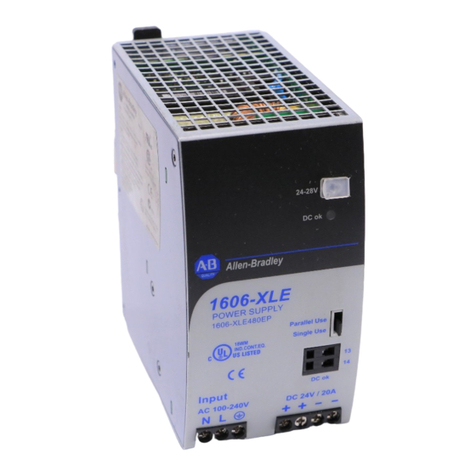
Allen-Bradley 1734-EP24DC User manual

Allen-Bradley

Allen-Bradley 1734-EP24DC User manual

Allen-Bradley 1771-p7 User manual

Allen-Bradley

Allen-Bradley 1771-p7 User manual

Allen-Bradley 1606-XLS240F User manual

Allen-Bradley

Allen-Bradley 1606-XLS240F User manual

Allen-Bradley Bulletin 1606 User manual

Allen-Bradley

Allen-Bradley Bulletin 1606 User manual

Allen-Bradley ControlLogix 1756-PA75/B User manual

Allen-Bradley

Allen-Bradley ControlLogix 1756-PA75/B User manual

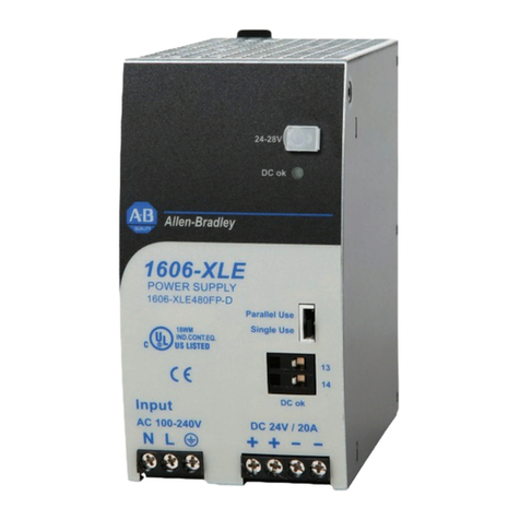
Allen-Bradley 1606-XLE480FP-D User manual

Allen-Bradley

Allen-Bradley 1606-XLE480FP-D User manual

Allen-Bradley SLC 500 User manual

Allen-Bradley

Allen-Bradley SLC 500 User manual

Allen-Bradley Bulletin 1606 User manual

Allen-Bradley

Allen-Bradley Bulletin 1606 User manual

Allen-Bradley ControlLogix 1756-PA75R/A User manual

Allen-Bradley

Allen-Bradley ControlLogix 1756-PA75R/A User manual

Allen-Bradley 1606-XLB240E User manual

Allen-Bradley

Allen-Bradley 1606-XLB240E User manual

Allen-Bradley 8720MC-RPS065 User manual

Allen-Bradley

Allen-Bradley 8720MC-RPS065 User manual

Allen-Bradley 1606-XLS960E-3 User manual

Allen-Bradley

Allen-Bradley 1606-XLS960E-3 User manual

Allen-Bradley 1769-PA2 User manual

Allen-Bradley

Allen-Bradley 1769-PA2 User manual

Allen-Bradley 1397 User manual

Allen-Bradley

Allen-Bradley 1397 User manual

Allen-Bradley Kinetix 5700 iTRAK User manual

Allen-Bradley

Allen-Bradley Kinetix 5700 iTRAK User manual

Allen-Bradley 1606-XLS960F-3 User manual

Allen-Bradley

Allen-Bradley 1606-XLS960F-3 User manual

Allen-Bradley 1606-XLE480FP User manual

Allen-Bradley

Allen-Bradley 1606-XLE480FP User manual

Allen-Bradley Kinetix 5700 User manual

Allen-Bradley

Allen-Bradley Kinetix 5700 User manual

Allen-Bradley 1771-P7 Series C User manual

Allen-Bradley

Allen-Bradley 1771-P7 Series C User manual

Allen-Bradley 1769-PB2 User manual

Allen-Bradley

Allen-Bradley 1769-PB2 User manual

Allen-Bradley 1606-XLPRED User manual

Allen-Bradley

Allen-Bradley 1606-XLPRED User manual

Allen-Bradley 140G-N User manual

Allen-Bradley

Allen-Bradley 140G-N User manual

Allen-Bradley Bulletin 1609 User manual

Allen-Bradley

Allen-Bradley Bulletin 1609 User manual

Allen-Bradley Rockwell Automation 1606-XLP60EQT User manual

Allen-Bradley

Allen-Bradley Rockwell Automation 1606-XLP60EQT User manual

Popular Power Supply manuals by other brands

Electro Plastics EPI-LX-R Series quick start guide

Electro Plastics

Electro Plastics EPI-LX-R Series quick start guide

TDK-Lambda Genesys Series user manual

TDK-Lambda

TDK-Lambda Genesys Series user manual

ACOPOWER PS5B-P1 user manual

ACOPOWER

ACOPOWER PS5B-P1 user manual

RuiDeng DPS Series manual

RuiDeng

RuiDeng DPS Series manual

Thermal Arc Fabricator 250C III Operation manual

Thermal Arc

Thermal Arc Fabricator 250C III Operation manual

STATRON 3225.71 Operating	 instruction

STATRON

STATRON 3225.71 Operating instruction

Cleaver Scientific powerPRO Series instruction manual

Cleaver Scientific

Cleaver Scientific powerPRO Series instruction manual

Omron S82H Series manual

Omron

Omron S82H Series manual

STAMOS S-LS-90 user manual

STAMOS

STAMOS S-LS-90 user manual

Eltek Valere PSR308/24-30 WIR user manual

Eltek Valere

Eltek Valere PSR308/24-30 WIR user manual

Crestron CNPWS-75 Operation guide

Crestron

Crestron CNPWS-75 Operation guide

Asus ROG Q20140b quick start guide

Asus

Asus ROG Q20140b quick start guide

NAPCO NP-P7ASUP installation instructions

NAPCO

NAPCO NP-P7ASUP installation instructions

Huawei UPS5000-S Series user manual

Huawei

Huawei UPS5000-S Series user manual

Lütze CPSF1-40-24 operating instructions

Lütze

Lütze CPSF1-40-24 operating instructions

Monster Power PowerCenter HDP2500 owner's manual

Monster Power

Monster Power PowerCenter HDP2500 owner's manual

ApPower Solar Outdoor Operation manual

ApPower

ApPower Solar Outdoor Operation manual

GW Instek PSB-2000 series user manual

GW Instek

GW Instek PSB-2000 series user manual

manuals.online logo
manuals.online logoBrands
  • About & Mission
  • Contact us
  • Privacy Policy
  • Terms and Conditions

Copyright 2025 Manuals.Online. All Rights Reserved.