ALLIED MEDICAL Ki Mobility Catalyst 5 User manual
Allied Medical Set-Up Guide
Ki Mobility Catalyst 5
Tools required:
• 2.5mm Allen Key
• 3mm Allen Key
• 4mm Allen Key
• 5mm Allen Key
• 5.5mm Allen Key
• 6mm Allen Key
• Utility Blade
• Rubber Mallet
• Two 8mm Spanners
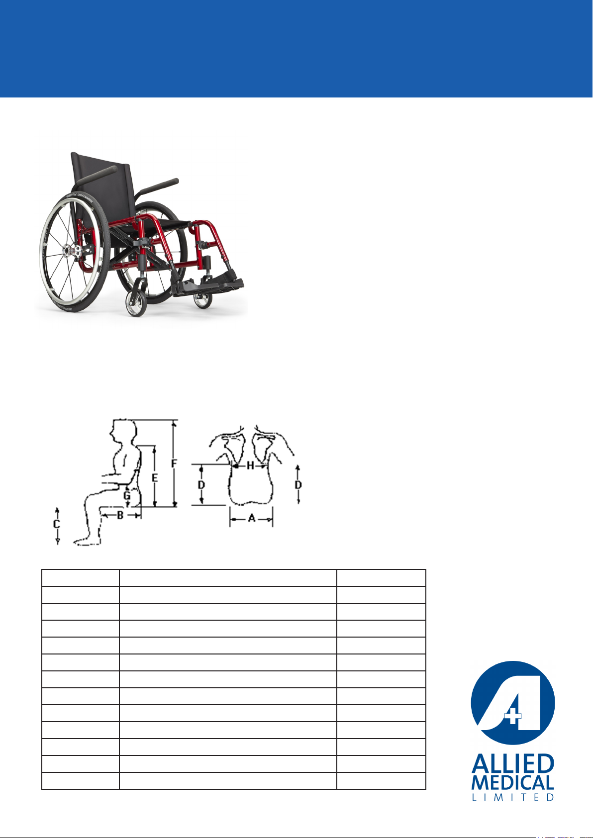
1. Required measurements for set up
Letter Body Part Required (Y/N)
AHip
B Thigh (Right)
B Thigh (Left)
C Right Leg
C Left Leg
D Right back height (below scapula)
D Left back height (below scapula)
E Shoulder to seat
F Top of head to seat
G Right elbow to seat
G Left elbow to seat
H Back width (below scapula)
• Two 10mm Spanner
• 13mm Spanner
• 17mm Spanner
• 19mm Spanner
• 24mm Spanner
• Phillips Screwdriver
• Wheelchair Script
2. Available adjustments and options
Seat Width
• Seat width is measured from the outside of frame tube on one side to the outside of frame
tube on the other side
• Check that there is enough room to slide your hand down between the armrest and thigh of
the user. If this is not possible, you need may to try a larger size. Pay particular attention if the
client is thin (ectomorph).
• Please note: the width is only adjustable on a Catalyst 5 with a width kit. Please note: width
adjustment would not be done at trial set up.
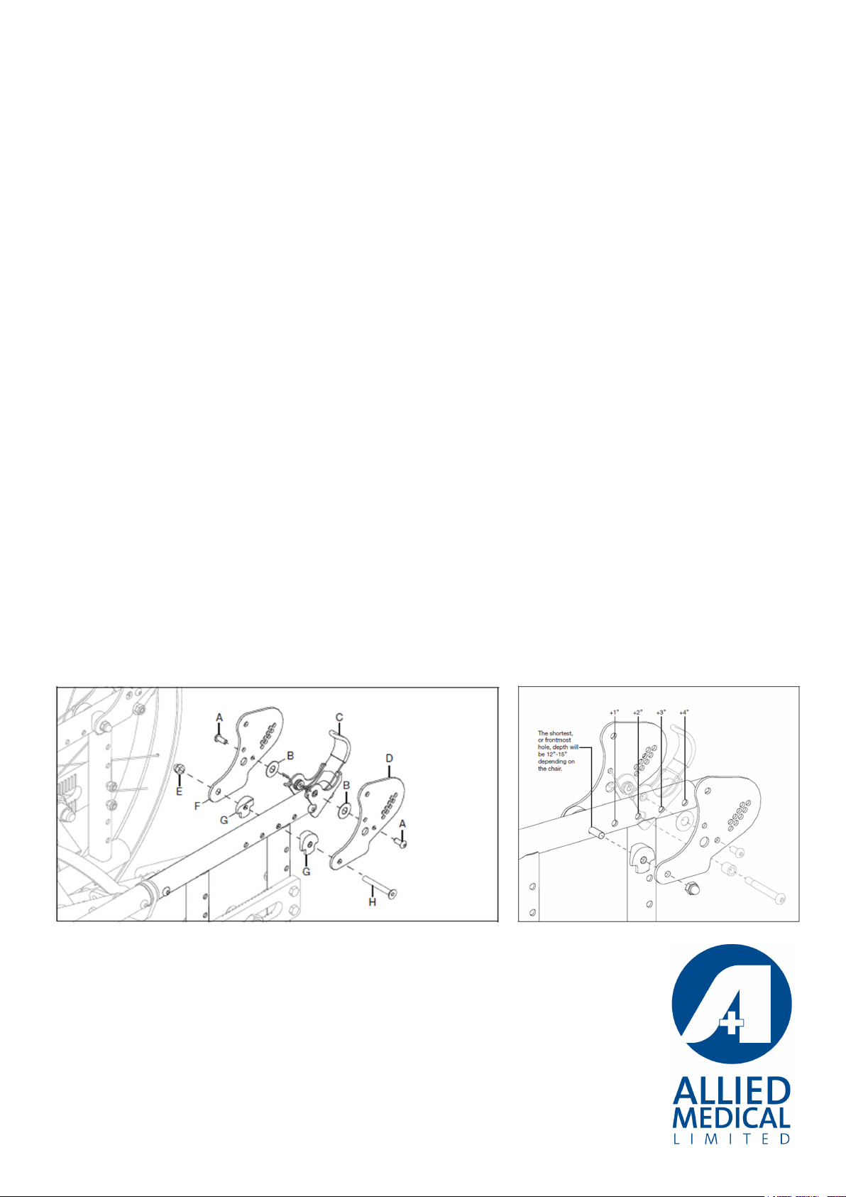
Adjusting the Seat Depth
This is only possible with a depth adjustable frame. 2” forward and 2” rearward adjustment with
minimum Seat Depth of 14” and maximum Seat Depth of 22”.
1. Remove the latch catch assembly using a 4mm Allen key and 10mm spanner, refer to the
bottom right bolt in the picture on the right
2. Remove bolt assembly (H) using 4mm Allen key and 10mm spanner
3. Reconnect to the latch assembly and set at desired depth determined by the holes available in
the frame(see diagram and table below).
4. Move the frame insert in or out so the latch assembly is in the correct place
5. Re-attach latch assembly according to the new depth that is required for the user
6. Re-attach the backrest plates onto the frame by installing bolt (H), two saddles (G) and nut (E)
using the 4mm Allen key and 10mm Spanner
7. Repeat steps on opposite side, or do both sides together if backrests are connected
Note: Always test to ensure the spring ends, in the latch mechanism, come out the backrest holes
that they align with
See link for video on depth adjustment: https://vimeo.com/131875623

Adjusting Seat to Footplate Height on a Front Mount Hanger
Front mount hangers oers from 3.5” knee-to-heel capability in .5” increments.
1. Remove screw (G) using a 5mm Allen key and 10mm spanner
2. Determine correct hole for the desired footrest height
3. Re-install screw (G), washer (E), saddle spacer (D), washer (C), washer (B) and nut (A) using a
5mm Allen key and a 10mm spanner.
4. Repeat steps on opposite side
Adjusting Seat to Footplate Height on an Extension Tube Hanger
Short, medium and long tubes are available – see table below for height ranges:
1. Remove the nut holding the extension tube in place using a 8mm spanner
2. Slide the extension tube up or down the hanger the appropriate height and line up the holes in
the hanger with the extension tube.
3. Re-tighten the nut ensuring that the bolt head sits in the groove in the composite casing.
Note: Take care to not over-tighten

Adjusting Footplate Angle
Innite adjustability available for more accurate placement of the foot
1. Loosen the two screws using a 4mm Allen key so the footplate moved
2. Determine optimal position for the user
3. Re-tighten the two screws ensuring the footplate is rmly set at new position
4. Repeat steps on opposite side if required
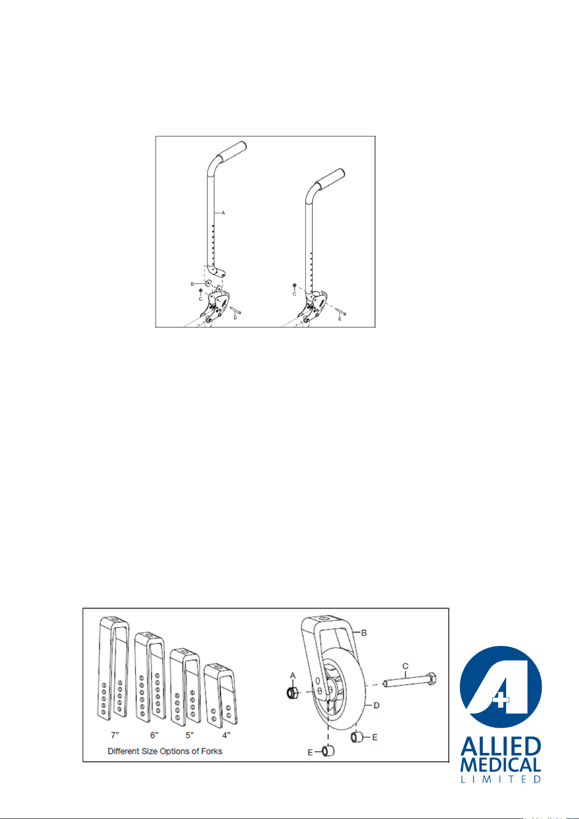
Adjusting Height Adjustable Back Post
1. Remove back upholstery or back support and attachment hardware if required
2. Remove the sleeve (C), bolt, washer (D) and nut (E) using a 4mm Allen key and 10mm spanner
3. Select appropriate height utilising the available holes on the back post (see diagram below for
height ranges)
4. Re-install the sleeve, bolt, washer and nut in hole selected and tighten using 4mm Allen key
and 10mm spanner
5. Repeat steps on opposite side
Adjusting Back Angle
1. Using a 5mm Allen key and a 10mm spanner remove screw (E) and nut (C).
2. Re-install screw (E) into the hole that gives the desired angle for the back post
3. Secure the back post by tightening the screw and nut (C)
4. Repeat on opposite side
Adjusting Front Seat Height
Note: There are dierent size options of forks and dierent height options with the holes in the
forks as shown in the diagram below:
Each hole is ½ an inch. You may require a dierent fork if you need to change the front seat height
by one inch or more. There are also 3 lengths of fork stem. Standard, ¾” extension and 1 ½”
extension. These may also be needed to change the height.
To adjust:
1. Remove the bolt (C) by using two 13mm spanners.
2. Re-install castor at new position on fork to achieve desired height ensuring the two spacers (E)
are fed through bolt on either side of the castor
3. Secure the with nut (A) using two 13mm spanners
4. Check that the castor spins freely
5. Repeat steps on opposite side
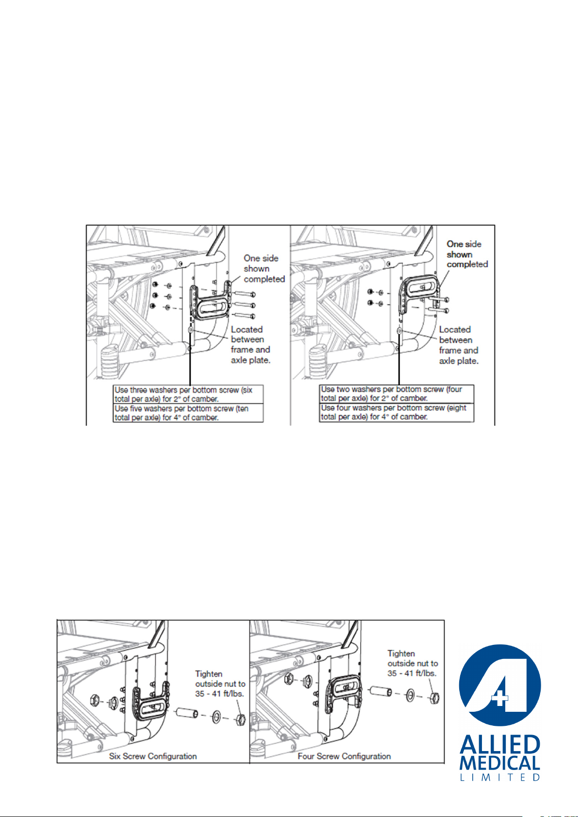
Adjusting Rear Seat Height with Universal Axle Plate
1. Remove rear wheels from quick release axle
2. Use a 10mm spanner to remove the nuts holding the axle in place (the recessed edge on the
axle plate holds the bolt head, so only one spanner is required
3. Reset to desired height on frame. Tip: lower and higher heights can be achieved by turning
the axle plate up or down as shown in the diagram below.
4. Re-install the bolts into the holes that achieve the desired height, tighten the nut using a
10mm spanner
Note: with this axle plate, camber is achieved with the lowest located washers that are between
the axle plate and the frame. See diagram below for dierent camber angles that can be
achieved.
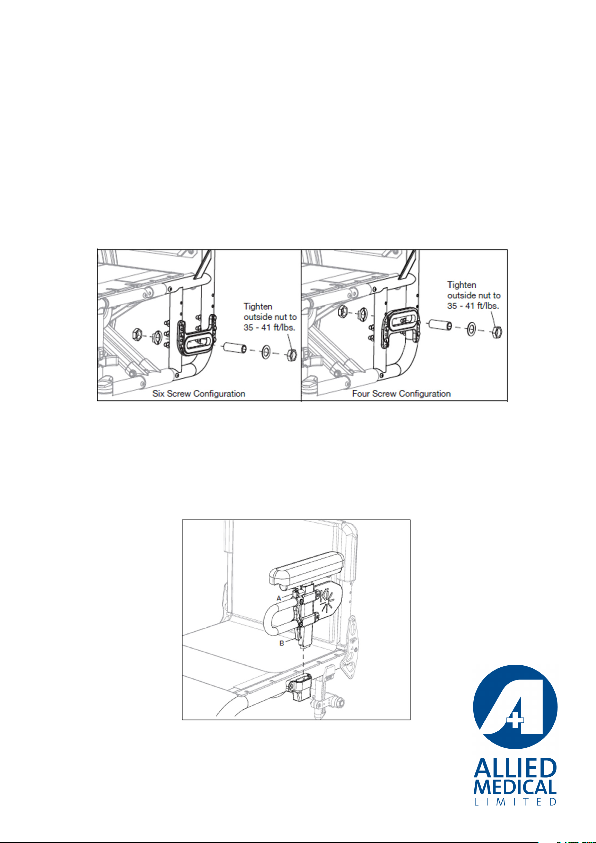
Adjusting Centre of Gravity
1. Remove rear wheels from quick release axle.
2. Loosen nut on outside of axle using a 24mm spanner until you are able to move the axle
receiver forward or back along to the next groove (on the inside of the axle plate). Move
forward for active centre of gravity or rearward for more stable.
3. Be careful to align the nut in the selected groove the correct way up so that it will hold in
place when tightened.
4. Re-tighten outside nut with 24mm spanner.
5. Repeat steps on opposite side taking care to ensure the same COG position is selected on
both sides.
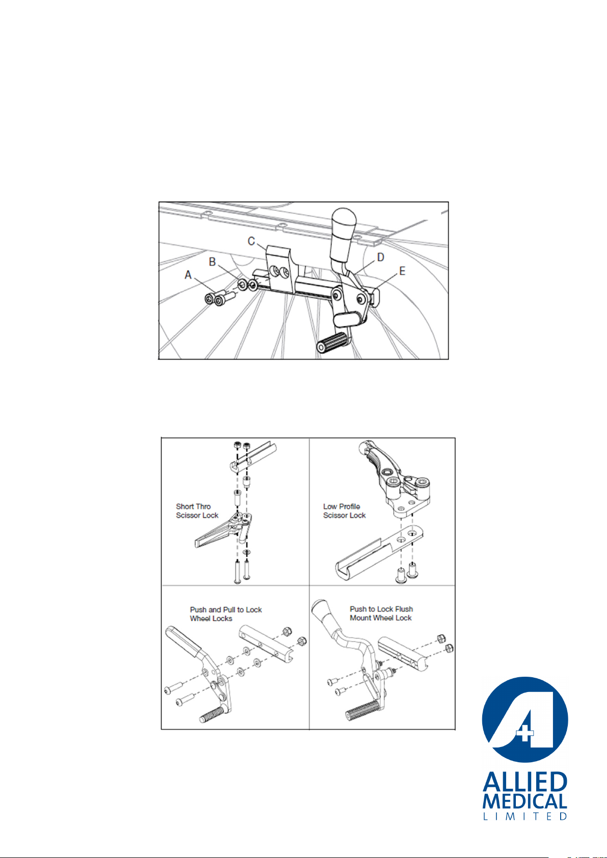
Adjusting Wheel Locks
1. Loosen the two screws (A) with a 5mm Allen key
2. The wheel lock clamps (C) can now be moved along the frame to the desired position so
that the wheel lock engages at least 1/8 inch into the tire and locks properly to prevent the
chair moving when engaged
3. Always retighten wheel lock hardware by alternating between the screws by tightening
a little at a time. This prevents over-clamping on one set of hardware which can lead to
binding of the fasteners and increased diculty in removal
4. Repeat steps on opposite side
Note: For a low profile scissor lock, use a 5mm Allen key to loosen the two bolts. For the other
three wheel locks, loosen the hardware using a 4mm Allen key and a 10mm spanner
Wheelbase Width Adjustment
Adjusting the wheelbase width allows the user the option to move the wheels closer or further
away from the hips. It also compensates for camber adjustment and gives the proper wheel
spacing to maximise pushing eciency.
To adjust:
1. Loosen the nut on the outside of the axle with a 24mm spanner, then turn the threaded axle
sleeve in or out to desired width.
2. Re-tighten the nut
3. Repeat on opposite side
Note: Check that there is sucient clearance so that the wheel does not rub on the side
guards, arm supports or wheel locks.
Adjusting T-Arm Height
1. Install T-Arm assembly into the receiver. Ensure the latch (B) “clicks” into place.
2. Adjust the height by loosening the height lever (A) and sliding the T-Arm post up or down.
3. Repeat steps on opposite side.
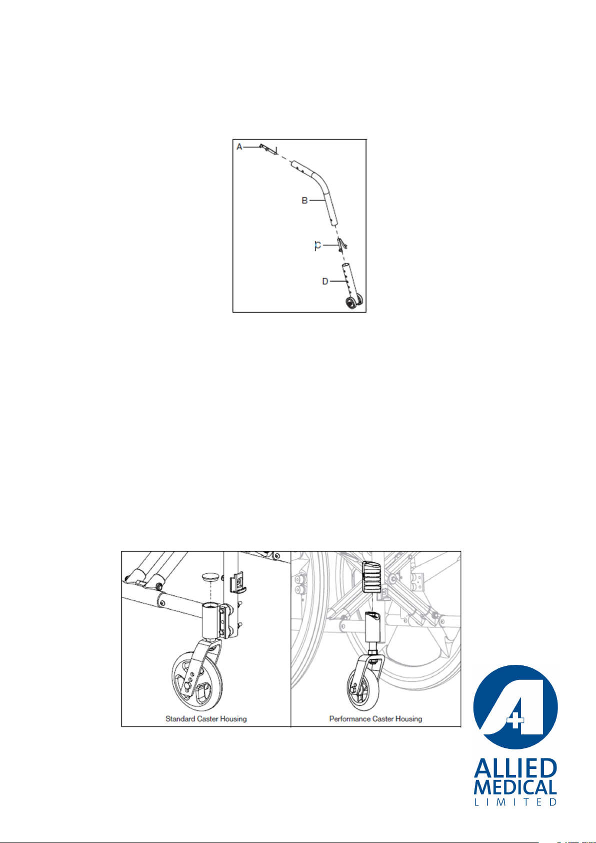
Adjusting Anti-tipper Height
1. Press in the detent button (C) to move the lower assembly (D) up or down.
2. Determine appropriate height from the holes available, install and ensure the detent buttons
“click” and lock into place
3. Ensure the height is set the same on both sides
Adjusting Catalyst Performance Castor Housing
1. Remove footrest for ease of adjustment
2. Take protective cover o the castor housing by pulling straight up
3. Using a 5mm Allen key turn each screw on the outside of the castor housing anti-clockwise
two complete rotations to loosen.
4. Locate the adjustment screw on the top of the top of the castor housing. Using the 5mm
Allen key turn the screw clockwise to move the castors forward away from the rear wheel.
Turn the screw anti-clockwise to move the castors rearward towards the rear wheel.
5. Keep turning the screw in the direction necessary to re-square the castors
6. Use a square against the front of the castor barrel check for castor squareness. Re-adjust if
necessary and recheck.
7. Re-tighten both screws on the outside of the castor housing until secure and replace the
cover.
8. Repeat steps on opposite side
See link for video on Performance Catalyst castor housing:
https://vimeo.com/149441646
For standard Catalyst castor housing – see link for video:
https://vimeo.com/149444977

Toe In/Toe Out
When you have wheels with camber it is important to get the wheels set up correctly. Toe in is
when the front of the wheels is closer together than the back of the wheels. It makes it so the
wheels are trying to come together when going forward. Toe out is the opposite; where the
wheels are trying to move away from each other.
To check this:
1. Put the wheel locks on and measure to the centre of the wheel hub
2. Mark this height on the front and rear of each tyre (a small piece of tape you can draw a line
on works well and is easy to remove after)
3. Now measure between the tyres at the front and at the rear at this height marker, the
distance should be the same
If there is toe in or toe out:
• A set of washers is 4 washers, one on each bolt, either front or back depending on toe in
or out, that hold the axle plate on. One washer will go on with the camber washers and
the other will go on the bolt above it. Putting an extra set of washers in will change the
measurement by around 8mm.
• If for example you have 516mm at the front and 500mm at the rear and your wheel centre
height is 305mm.
• Take the wheels o and loosen all the bolts holding the axle plate in place.
• Remove the two rear bolts, without losing the camber washers, and fit 2 more washers on
each bolt between the axle plate and the frame. Do this on both sides.
• Tighten all axle bolts and put the wheels back on.
• Measure the height marks used before and make sure they are all 305mm and put the wheel
locks on.
• Check the heights again as they can move when putting the wheel locks on.
• Measure the front and rear width again and both should be around 508mm. It is preferable
to have toe in rather than toe out as an exact adjustment is hard to get with the washers.

3. Tips & Tricks
Note: If the user is trialling dierent cushions and back supports you may need to re-adjust seat
depth and seat to footplate lengths to accommodate the dierent proles of the seating.
4. Checklist
What to check Done
Seat Width
Seat Depth
Seat to foot plate length/angle/depth
Back height and angle
COG – shoulder position and access to rear wheel
Seat height - shoulder position and access to rear wheel
Seat rake – for optimal pelvic positioning
Wheel locks at optimal tension for client
Wheel base width – optimal position for access to rear wheel
Positioning belt (if applicable)
Arm rest height (if applicable)
Check push handle height/position (if applicable)
Anti-tipper position (if applicable)
Castor position – set at 90 deg to floor
Other ALLIED MEDICAL Wheelchair manuals
ALLIED MEDICAL
ALLIED MEDICAL Varilite Icon Mid Back User manual

ALLIED MEDICAL
ALLIED MEDICAL Q-Logic 2 User manual
ALLIED MEDICAL
ALLIED MEDICAL Varilite Icon Deep Back User manual

ALLIED MEDICAL
ALLIED MEDICAL KARMA KM8020 User manual

ALLIED MEDICAL
ALLIED MEDICAL Enhanced Display User manual

ALLIED MEDICAL
ALLIED MEDICAL KP25 User manual

ALLIED MEDICAL
ALLIED MEDICAL Shark User manual

ALLIED MEDICAL
ALLIED MEDICAL Ki Mobility Rouge User manual

ALLIED MEDICAL
ALLIED MEDICAL KARMA 8020 User manual

ALLIED MEDICAL
ALLIED MEDICAL Quantum Q6 Edge 2.0 User manual


