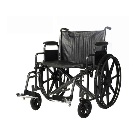
ALLIED MEDICAL KARMA 8020 User manual

KARMA 8020 SELF PROPELLING WHEELCHAIR
KARMA 8520 TRANSIT WHEELCHAIR
USER MANUAL

AFlip-back, heigh-adjustable armrest with desk-length arm pad
BPush-to-lock brakes
C70-degree legrests with calf strap
DPlastic footplate
EHeight-adjustable backrest
FQuick release, removable rear wheels
GAnti-tippers
H8” x 1” solid castor
ITransit rear wheel
JRubber grip handles
SPECIFICATIONS
14”, 16”, 17” 18”, 20”, 22” 16”, 18”
Options: 1” and 2” (+/-)
customisation for 14”-
20” width frames
Transit 12.5”
Self Propel 24”
Options: 22” x 20”
8” x 1” solid
Options: 8” x 2” pneumatic
6” x 1” solid or pneumatic
Self Propel:
Seat width + 9”
Transit: Seat width + 6”
8.5” min
11.5” max
15.5”
Options: 18.5” with
upholstery extension
22” with extended back
canes
19”
Options: Customised
configurations 16” - 21”
32” (42” with 70-deg
hangers)
35”
Options: 38” with 22”
back canes
Transit 13.5 kg
Self Propel 15.5 kg
(With all standard features)
14”-18” width frames
130 kg
20”-22” width frames
160 kg
Seat width Seat depth Rear wheel Front castor
Seat to floor
height
Back height Armrest height Overall width
(when open)
Overall length Overall height User weight limit Wheelchair weight
1.1 General
Only maintenance and service as described in this manual should be carried out. Use
only genuine replacement parts.
1.2 Using the KM8020 series
Always make sure BOTH brakes are applied before getting into or out of the
wheelchair.
Always take care when climbing kerbs or turning on slopes.
Never stand on the footplates when getting in or out of the wheelchair.
Never go down steps forward.
Never carry more than one passenger.
1.3 Notes for attendants and users
Do ensure that the brakes are always on when the wheelchair is not being pushed.
Always make sure that both of the user's feet are safely on the footplates and that
their clothing is safely tucked out of the way and cannot catch in the wheel.
Always keep both hands on the push handles to control the wheelchair.
Always look well ahead to anticipate hazards such as furniture, doors or potholes.
Always avoid soft surfaces because the wheelchair may get bogged down.
Always be careful not to go too fast or turn quickly and try to achieve a smooth
steady ride.
PLEASE keep in contact with the person in the wheelchair. If you stop to look in
shop windows or talk to people remember to turn the chair so that the person in
the wheelchair does not have to turn.
NEVER put on the brakes too suddenly or too firmly as this may tip the user out of
the wheelchair.
1.4 General Misuse
Please note that our USER GUIDE contains a number of cautions. Any vehicle can
cause injury if misused. Use your wheelchair with reasonable care and within these
guidelines and your safety will be ensured.
If used sensibly and carefully, your wheelchair will give you years of safe use.
Be aware that careless use endangers your own safety as well as that of others.
ALWAYS follow the road code when outdoors and also the guidelines written in this
manual.
Page 1
Page 14
E
F
G
H
A
B
C
D
A
C
D
H
G
B
I
E
J
2. WHEELCHAIR OPERATION
2.1 PREPARING FOR USE
2.1.1 Unfolding the wheelchair
Step 1: With the wheelchair in front of you, take hold of both the armrests
and pull them apart until the backrest is almost completely open.
Step 2: Place hands on the top of the seat support rails with your fingers
pointing inwards and push down until the seat is completely open
and the seat rails are fully located in the retaining cups.
CAUTION: When completing step 2, never put your fingers around the sides or
under the chair as they can become trapped between the seat rail
and the frame.
2.1.2 Folding the wheelchair
Step 1: Flip up the footplates.
Step 2: Un-velcro the backrest from the seat.
Step 3: Put fingers under the middle of the seat at both front and rear,
grasp and give a sharp pull upwards until the wheelchair is nearly
closed. Never grasp from the sides.
Step 4: Push the armrests together.
Step 1 Step 2
Step 1 Step 3
Page 2
Page 13

4. MAINTENANCE
4.1 CLEANING AND TYRE CARE
4.1.1 Cleaning
Clean the upholstery with a biological cleaning agent such as is recommended for
cleaning kitchen work surfaces. Do not use any propriety cleaning fluids as these may
damage the upholstery. Clean chrome and painted surfaces with a wax polish spray
or simply wipe over with a clean soft duster.
4.1.2 Tyres
The KM8000 manual wheelchair is fitted with a maintenance free castor and 12 ½” x
2 ¼” pneumatic rear tyre (transit wheelchair) or a 24” x 2 ¼” pneumatic rear tyre
(self-propelling wheelchair). It is advisable to check the air pressure of these
components every two weeks. This can be done either at a service station or with a
standard bicycle pump.
4.2 MAINTENANCE CHECKS
Every week check the following items for damage or excessive wear:
Upholstery and occupant restraints where fitted.
Every month examine the following items for effective operation e.g. damage and
general wear and tear:
Seat and backrest cushions
Armrest latch lever and clamp handle
Armrest pads
Brakes
Antitippers
Castors for free rotation of castor wheel and castor unit
Tyre tread depth
For repairs, please contact your service contractor.
2.1.3 Footrest Adjustments
Footrest Removal and Refitting
To remove the footrest push/pull the release lever and rotate the footrest until it faces
outwards. To lift off, pull upwards.
To refit, locate the footrest unit onto the frame lugs (at about 90 degrees to the side of
the frame) and rotate it inwards until the unit locks into place (you will hear a click).
CAUTION: The occupant's leg must be supported or resting safely, while
executing the above adjustments.
To adjust footplate height
Step 1: To adjust footplate height, use tool
provided to loosen the bolt at the
bottom of the footrest stem.
Step 2: Adjust to the required height and
retighten.
2.1.4 Antitip bars for wheelchair
NOTE: For the users safety, these must be fitted.
To fit: Depress rear location button on the antitip bar
and slide into rear of frame tube. The front button
MUST engage through the hole in the frame. Check
antitip is secure by attempting to push backward and
forward. Follow these instructions to fit the atnitip bar
on the other side of the wheelchair.
2.2 GETTING IN AND OUT
2.2.1 Getting in
Step 1: Engage both brakes.
Step 2: Lift up the footplates and swing footrest to the side.
Step 3: The user should now lower themselves into the seat using the
armrests as supports (if possible).
Step 4: Push the footplates back down and re-locate the footrests so that
Page 3
Page 12
Brake Clamp Transit Axle Block
Position
Figure 3.7.3
Figure 3.8.1
Figure 3.8.2
Figure 3.8.3
Standard
Front of Chair
Antitipper
Wheel mounting
Bracket
M5 Nut and Bolt
Amputee
Wheel mounting
Bracket - Standard
Mount
Step 3: Use the larger bottom hole on
the block (see fig 3.3.3) to mount
the transit wheel. The block
should be pointing towards the
ground with the flat side of the
block facing outwards away from
the frame.
3.8 CHANGING FROM STANDARD CONFIGURATION TO AMPUTEE
SETTING
Step 1: Remove hangers, quick-release
wheels and axles. Place
wheelchair on bench/table or
floor as shown in figure 3.8.1.
Step 2: Remove the two M6 nuts and
bolts with a 5mm allen key and
10mm spanner (as supplied in
Karma tool kit).
Step 3: Reposition wheel mounting
bracket as required. Replace
bolts, washers and nuts and
tighten. Replace quick-release
wheels, loosen brake clamps with
a 5mm allen key and slide along
frame to suit new wheel position.
HANDY HINT: Work on one side at a time so the other side can be used as
reference for correct brake positioning.
NOTE: If changing from amputee setting back to standard configuration
move the brake before replacing the quick-release wheels.
the user can place their feet upon them.
Step 5: Release the brakes.
CAUTION: Never stand on the footplates when getting into or out of the
wheelchair.
Always ensure that the front castors are in line with the rear wheels and pointing
forwards and that the back of the wheelchair is secure against either a wall or firmly
held by an attendant.
2.2.2 Getting out
Step 1: Make sure that the wheelchair is as close as possible to the transfer
point.
Step 2: Back the wheelchair sufficiently to ensure that the castors are
pointing forward i.e. in line with the rear wheels and usually with the
castor forks pointing forward. Ensure that where possible the rear of
the wheelchair is against the wall or, if not, it must be firmly held by
an attendant.
Step 3: Engage both the brakes.
Step 4: Lift up the footplates and swing the footrests to the side.
Step 5: Slide forwards on the seat.
Step 6: Place one foot firmly on the ground with the knee at right angle and
the other foot slightly apart and further back.
Step 7: Place your hands on the front of the armrests and moving your
weight forward, bring your head and shoulders up over your knees as
you push yourself up.
CAUTION: Never stand on the footplate when getting out of or into the
wheelchair.
2.3 TRANSFERS
The following instructions apply to users with sufficient mobility to get in and out of
the wheelchair without assistance. However the instructions are still valid where
assistance is required and will help where other aids such as transfer boards or hoists
are used. Before transferring to or from the wheelchair, make sure you are as near as
possible to your point of transfer and that the brakes are applied.
Page 4
Page 11

2.3.1 Forward Transfer - Getting into the wheelchair
Remove or swing the legrests to the side.
Lower yourself into the wheelchair using the armrests for support or with the help of
a caregiver.
Refit or swing the legrests back into place, taking care not to catch yourself, and place
your feet on the legrests.
2.3.2 Forward Transfer - Getting out of the wheelchair
Remove or swing the legrests to one side.
Move forward in the seat until your feet can reach the floor or you are balanced on
the edge of the seat.
Place your hands on the front of the armrests and move forwards lifting yourself up
and out of the wheelchair.
2.3.3 Side Transfer - Getting into the wheelchair
Lift back armrest to clear the seat.
Ensure brake is on.
Remove or swing the legrests to one side.
Place one hand on the wheelchair seat and ease yourself onto the seat.
2.3.4 Side Transfer - Getting out of the wheelchair
Ensure brake is on.
Remove or swing the footrests to one side.
Remove armrest to clear the seat.
Place one hand on the point of transfer and ease yourself out of the wheelchair.
2.4 OTHER IMPORTANT THINGS YOU SHOULD KNOW
Flammability Do not expose the wheelchair to heat sources e.g. heaters and fires.
Direct exposure of the wheelchair to a flammable source must be
avoided.
Resting Note that the upholstery has been designed for comfort in
general use. Users that are susceptible to pressure sores should also
use a pressure relief cushion.
3.6.2 To remove the seat upholstery
Located on each side of the seat is a row of
screws that securely hold the seat upholstery
in place. This is covered with an extended
section of the upholstery and fastened with
Velcro over the screws to protect the user
from damaging their skin.
Step 1: To remove the seat upholstery, undo the Velcro on the extended
upholstery on each side and undo each screw.
Step 2: The seat upholstery can now be removed and custom seating can be
fitted.
Step 3: To replace the seat upholstery, line up the hole in the seat upholstery
with the holes in the cross bar and replace each screw and washer
and tighten.
3.7 CONVERT WHEELCHAIR FROM SELF PROPEL TO TRANSIT
Step 1: Remove the hangers, quick-release wheels
and axles. Place wheelchair on
bench/table or floor as shown in fig 3.7.1.
Step 2: Remove the two M6 nuts and bolts
located on the axle block with a 5mm
allen key and 10mm spanner (as supplied
in Karma tool kit). Remove the existing
axle blocks. Mount the new transit block
in front of the antitipper and replace the
two nuts and bolts into the smaller holes.
Figure 3.6.2
Figure 3.7.1
Figure 3.7.2
Wheel mounting
Bracket - Standard
Mount
Standard
Front of Chair
Antitipper
Wheel mounting
Bracket
M5 Nut and Bolt
Page 5
Page 10
Step 3: Slide the backcanes up or down to the desired height
As the backcanes are shifted, the back upholstery will move
accordingly. There are a number of holes running vertically through
the lower portion of the backcane. These determine how much the
back height can be raised or lowered.
CAUTION: For safety reasons, in the highest position the top two bolts must still
pass through the square tubing of the frame and the holes running
through the round tubing of the backcane.
Step 4: Replace the top two bolts on both backcanes.
Replace all washers. Tighten each bolt and nut to a point where firm
but not crushing the frame.
Step 5: Replace the third lower bolt on both backcanes if they have been
removed.
3.6 REMOVING THE SEAT OR BACK UPHOLSTERY
3.6.1 To remove the back upholstery
Step 1: Remove the rubber grip handles. By
slightly heating them with a hairdryer and
twisting them whilst pulling them off, will
make removing of these easier.
Step 2: Undo the two screws that are located
underneath the rubber grip handles at the
rear of each back cane (see fig. 3.6.1).
Step 3: Slightly fold the wheelchair by putting fingers under the middle of the
seat at both front and rear, grasp and give a sharp pull upwards until
the wheelchair is nearly closed.
Step 4: Slide the back upholstery off the backcanes.
Step 5: A tension adjustable or custom back can now be fitted.
Step 6: Once the new back has been fitted slide rubber grip handles back
onto back canes with a twist and push movement, ensuring they're
placed back in their original position.
Figure 3.6.1
3. MINOR WHEELCHAIR ADJUSTMENTS
3.1 ADJUSTING ARMREST HEIGHT
Standard flip-back armrest:
The armrest flips back by pressing the release lever located at the front base of the
armrest. After you press the release lever (fig 3.1.1), you can you lift the armrest
backwards.
To adjust the height of the armrest, simply pull out the silver bolt located underneath
the armrest pad (see fig 3.1.3) and hold onto it whilst adjusting the height of the
armrest. Release sliver bolt once desired height is achieved to securely lock armrest
back in place (see fig 3.1.4).
3.2 QUICK RELEASE REAL WHEELS
3.2.1 To remove rear wheel ensure the brake is off.
Step 1: Support the weight of the
wheelchair with one hand by
holding the push handle.
Step 2: Push the hub cover and hold
Figure 3.1.1 Figure 3.1.2
Figure 3.1.3
Figure 3.1.4
Figure 3.2 Page 6
Page 9

Step 3: To adjust the angle of legrest, pull on the lever located underneath
the seat whilst pulling legrest upwards or pushing down. Release
lever once desired angle has been achieved to lock legrest securely
into place.
To adjust the height of the legrest undo bolt located above footplate, pull or push the
bar until desired length is achieved, line two holes up and replace bolt and tighten.
3.5 ADJUSTING THE BACK HEIGHT
Where to adjust the backcane height
When looking at the rear of the
wheelchair, where the round
backcane tubes meet and enter
the square tubes of the frame,
three bolts are visible. By removing
these bolts it is possible to adjust
the height of the back.
Adjusting the back height
Step 1: Remove the two top bolts on each side of the backcanes (see arrow
A in fig 3.5 above) - 4 bolts in total
One pair of identical 5mm allen key head bolts are positioned closely
together and towards the top of the square frame tubing. These run
through both the frame and the backcanes. They are attached with a
nut and spaced with small washers.
Step 2: Remove the lower bolt on each cane if necessary (see arrow B in
see fig. 3.5 above) - 2 bolts in total
A third bolt is attached through the rear of the swingaway armrests
and the square frame tube.
This bolt is located directly below the bolts described in Step 1. It is
above and unrelated to the axle block and bolts that attach the wheel
to the frame.
*Only when the backcanes are already set relatively low will this bolt also
have to be removed to adjust the backcane height.
A
B
Figure 3.5
Step 2(cont): down the quick-release mechanism (see fig 3.2).
Step 3: Pull the wheel off.
3.2.2 To attach the rear wheel
Step 1: Ensure that the brake is in the OFF position.
Step 2: Take up the assembled wheel and axle and press the button in the
centre of the axle. This retract the ball bearings that will allow you
to push the axle into the wheel bracket that is located on the lower
rear frame of the wheelchair.
Step 3: Remove your thumb from the button on the axle, the ball bearings
should now be visible protruding from the axle at the back of the
wheel bracket. The wheel should now be secured safely in the frame.
3.3 FITTING AND ADJUSTING A STUMP SUPPORT
Step 1: Remove the standard footrest by pulling
the release lever and rotate the footrest
until it faces outwards. Lift and remove.
Step 2: Locate the stump support onto the
frame lugs (at about 90 degrees to the
side of the frame) and rotate it inwards
until the support locks into place.
Step 3: To adjust the height, undo the bolt located on the bar underneath the
stump support, lift the support until the desired height is achieved,
replace the bolt and tighten.
3.4 FITTING AND ADJUSTING AN ELEVATING LEGREST
Step 1: Remove the standard footrest by pulling
the release lever and rotate the footrest
until it faces outwards. Lift and remove.
Step 2: Locate the elevating legrest onto the
frame lugs (at about 90 degrees to the
side of the frame) and rotate it inwards
until the legrest locks into place.
Figure 3.3
Figure 3.4
Page 7
Page 8
This manual suits for next models
2
Table of contents
Other ALLIED MEDICAL Wheelchair manuals
ALLIED MEDICAL
ALLIED MEDICAL Quantum Q6 Edge 2.0 User manual
ALLIED MEDICAL
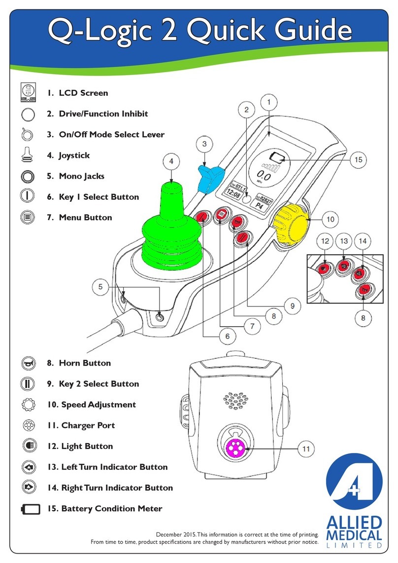
ALLIED MEDICAL Q-Logic 2 User manual

ALLIED MEDICAL
ALLIED MEDICAL Ki Mobility Rouge User manual
ALLIED MEDICAL
ALLIED MEDICAL Varilite Icon Mid Back User manual
ALLIED MEDICAL
ALLIED MEDICAL Varilite Icon Deep Back User manual
ALLIED MEDICAL
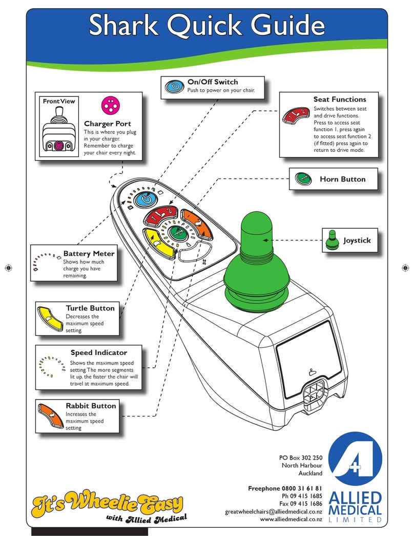
ALLIED MEDICAL Shark User manual
ALLIED MEDICAL
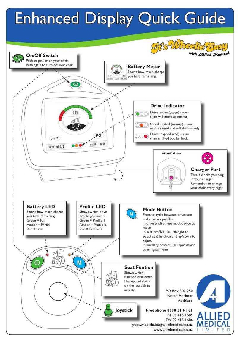
ALLIED MEDICAL Enhanced Display User manual
ALLIED MEDICAL
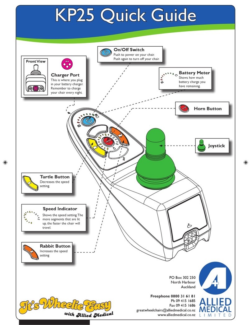
ALLIED MEDICAL KP25 User manual
ALLIED MEDICAL
ALLIED MEDICAL Ki Mobility Catalyst 5 User manual

ALLIED MEDICAL
ALLIED MEDICAL KARMA KM8020 User manual

