manuals.online logo
Brands
  1. Home
  2. •
  3. Brands
  4. •
  5. ALLIED MEDICAL
  6. •
  7. Wheelchair
  8. •
  9. ALLIED MEDICAL Ki Mobility Rouge User manual

ALLIED MEDICAL Ki Mobility Rouge User manual

Allied Medical Set-Up Guide
Ki Mobility Rouge
Tools required:
• Allen keys: 2.5mm; 3mm; 4mm; 5mm; 6mm
• Utility Blade
• Two 8mm spanners
• Two 10mm spanners
• 13mm spanner
• 17mm spanner
• 19mm spanner
• 24mm spanner
• Phillips screwdriver
• Punch or small screwdriver
• Script
1. Required measurements for set up
Letter Body Part Required (Y/N)
AHip
B Thigh (Right)
B Thigh (Left)
C Right Leg
C Left Leg
D Right back height (below scapula)
D Left back height (below scapula)
E Shoulder to seat
F Top of head to seat
G Right elbow to seat
G Left elbow to seat
H Back width (below scapula)
2. Available adjustments and options
Seat Width
• Seat width is measured from the outside of the frame tube on one side to the outside of the
frame tube on the other side.
• Check that there is enough room to slide your hand down between the armrest and thigh of
the user. If this is not possible, you need may to try a larger size. Pay particular attention if the
client is thin (ectomorph).
• Please note: the width is only adjustable on a Rogue XP with a width kit. Will require a new
chair if width is not correct on a Rogue. Rogue XP width adjustment would not be done at trial
set up.
See web link for Rogue XP Width adjustment: P.66
https://www2.kimobility.com/TechnicalManuals/Rogue_Tech_Manual.pdf
Adjusting the Seat Depth
• Seat depth is measured from the front of the back posts to the front edge of the seat sling.
• Check that you are able to put two ngers side by side behind the user’s knee before hitting
the seat upholstery. If not, then you need to extend to a longer seat depth. Alternatively, you
don’t want the depth too long which can cause pressure areas at the back of the calf.
To adjust the depth (do both sides together):
1. Remove the 2 bolts (L) to move the backrest assembly forward or back on the frame. Choose
the conguration that best suits the user based on the frame holes available.
2. Re-secure the backrest assembly to the frame by installing the two bolts (L), saddleback (M),
two saddles (B) and two nuts (A) using a 4mm Allen key and a 10mm spanner.
Adjusting the footrest
Height adjustment:
1. Loosen the set screw on each side of the frame (A) using a 3mm Allen key. Be careful not to
loosen all of the way.
2. Adjust footrest tube up or down to achieve the desired height (B).
3. Ensure both sides are adjusted equally.
4. Re-tighten each set screw.
Angle adjustment:
1. Loosen the two screws (D) and two nuts (H) using a 5mm Allen key.
2. Set to desired angle for the user – ensure the nuts are set in the correct position under the
footrest adjustable clamp (G), then re-tighten the screws.
High Mount Footrest Height Adjustment:
1. Loosen the two screws (A) using a 5mm Allen key which will allow you to move the clamps
(C&D) up or down the frame tubing.
2. Set at appropriate height for the user and take care checking both sides are equal.
3. Re-tighten the screws.
Adjusting Height Adjustable Back Post
1. Remove the screws (C) and threaded barrels (D) using two 3mm Allen keys, adjust the back
posts to desired height.
2. Replace the screws and threaded barrels to secure the back posts.
Note: a 5mm Allen key through the holes will help line up the holes as the barrels are a tight t.
Adjusting Back Post Angle (do both sides together):
1. Remove bolt (H) using a 3mm Allen key.
2. Loosen I and E
3. Set the angle of the back rest by turning the arc adjustment cam and aligning the cam holes
with the backrest plate holes. Once the desired angle is achieved secure by reinstalling the bolt
and lock washer (G).
4. Tighten I and E
5. Repeat steps on opposite side. Ensure the same mounting and angle holes are used so both
sides of the backrest match.
Adjusting Centre of Gravity:
Adjust the centre of gravity (COG) by moving the two camber mount clamps (A) forward or
rearward on the seat tube (B).
1. To adjust centre of gravity location
a. Remove rear wheels
b. Loosen the two screws and nuts that secure the camber mounts (A) to the seat tubes
c. Slide the camber mounts forward or rearward along the seat tube to the desired hole
location
d. Do both sides together
e. Ensure the mounts on both side of the frame are adjusted equally on both sides of the
frame before tightening all the screws and nuts
f. Once the camber mount clamps are secured, attach the rear wheels
2. Changes to the COG may aect the rear seat height, toe-in/toe-out of the rear wheels and
squareness of the castors. Re-adjust all of these settings as necessary.
3. Adjusting the COG will require re-adjusting the location of the wheel locks (if provided).
See link for video:
https://vimeo.com/81234382
Seat Height Adjustment:
1. Rear Seat Height
a. Remove rear wheels from quick release axle
b. Use a 4mm Allen key and 8mm spanner to remove the two bolts (A) holding the upper
and lower mounting brackets together.
c. Reposition the mounting brackets to the desired height and replace the two bolts
d. Do both sides together
Note: Height adjustments are in ¼ inch increments
2. Front Seat Height
a. Can be adjusted in ½ inch increments by repositioning the castor wheel with the fork
b. Use two 4mm Allen keys to remove the cap screws and push internally threaded axle
from one hole location and move up or down to the desired location.
c. Reposition the two screws and tighten
d. Re-square castor wheels
Adjusting Wheel Locks:
1. Loosen screws (A) with a 5mm Allen key
2. The wheel lock clamps (C&D) can now be moved along the frame to the desired position so
that the wheel lock engages at least 1/8 inch into the tire and locks properly to prevent the
chair moving when engaged
3. Always re-tighten wheel lock hardware by alternating between the screws by tightening
a little at a time. This prevents over-clamping on one set of hardware which can lead to
binding of the fasteners and increased diculty in removal
Wheelbase Width Adjustment:
Adjusting the wheelbase width allows the user the option to move the wheels closer or further
away from the hips. It also compensates for camber adjustment and gives the proper wheel
spacing to maximise pushing eciency.
To adjust:
1. Loosen the nut (A) with a 24mm spanner, then turn the threaded axle sleeve (B) in or out to
desired width.
2. Re-tighten nut (A)
3. Repeat on opposite side
Note: Check that there is sucient clearance so that the wheel does not rub on the side
guards, arm supports or wheel locks.
Adjusting T-Arm Height
1. Install T-Arm assembly into the receiver. Ensure the latch (B) “clicks” into place.
2. Adjust the height by loosening the height lever (A) and sliding the T-Arm post up or down.
3. Repeat steps on opposite side.
Attaching Bolt-On Push Handle
1. Install the clamps (B&C) and bolt-on push handle tube (E) onto the rigidiser bar and secure
with two screws (A) and two nuts (D) using a 5mm Allen key
2. Repeat steps with the second bolt-on push handle
3. To adjust push handle height this is only possible with an adjustable height rigidiser bar.
Note: Back rest clamps on the back canes may limit adjustment. If desired height of push
handle cannot be achieved -shorter or longer push handles may need to be installed.
Note: The clamps come in two orientations: straight or angled. See below for details.
Adjusting Rigid and Ergo Stroller Handle:
Note: Ergo stroller handles only available on Rogue XP
1. To loosen the clamp, turn the clamp handle (D) anti-clockwise until the stroller handle can
slide freely up or down in the clamp
2. Set to desired height
3. Re-tighten the clamp by turning the clamp handle clockwise until firm and the stroller
handle stays securely in place
4. Repeat steps for second stroller handle (if applicable)
Note: The detent button on the bottom of the back post will click into place when properly
installed.
Adjusting Anti-tippers
The anti-tip receiver (B) can be adjusted up or down on the camber tube by removing the two
screws (A) with a 4mm Allen key and 8mm spanner
1. Check desired position and secure with the two screws and nuts (C). Tighten screws
2. Install the anti-tip assembly (D) into the receiver until the button “clicks” into place
3. Shorten or lengthen the anti-tip tube by pressing in the detent button and resetting to
desired height available. Check the button “clicks” back into place
Adjusting the Castor Angle:
For optimum performance, the castor housing should always be at 90° angle to the floor
(perpendicular to the ground).
1. To change the angle, you will need an M5 Allen key.
2. Loosen the M8 button head screw (A) on the bottom of the castor housing wing. Turn the
screw on the top of the castor housing wing (B). Loosening will begin to tilt the castor
forward. By tightening, you will turn rearward.
3. Turn until you have aligned the castor stem so it is perpendicular to the floor.
4. Place a large right triangle against the flat surface of the fork as shown.
5. With the rack and pinion* system of the Rogue, the castors can always be adjusted to be
square.
See link for video:
https://vimeo.com/81235091
*RP Tuning is unique to the Rogue and is the
only castor adjustment system which gives
perfect alignment for everyone at any seat
angle. The modified rack and pinion gear is
infinitely adjustable over any range and can
be adjusted while the chair is occupied. It’s as
simple as tightening and loosening a screw.
No small components to take apart and put
back together.
Toe In/Toe Out
When you have wheels with camber it is important to get the wheels set up correctly. Toe in is
when the front of the wheels is closer together than the back of the wheels. It makes it so the
wheels are trying to come together when going forward. Toe out is the opposite; where the
wheels are trying to move away from each other.
To check this:
1. Put the wheel locks on and measure to the centre of the wheel hub
2. Mark this height on the front and rear of each tyre (a small piece of tape you can draw a line
on works well and is easy to remove after)
3. Now measure between the tyres at the front and at the rear at this height marker, the
distance should be the same
If there is toe in or toe out:
• Release the bolt clamping the camber tube on both sides.
• Check that there are no grub screws in the clamp mount.
• Gently twist the camber tube, making sure not to slide it sideways and
tighten the bolts again. You won’t need to twist it far and when tightening
up just make it, so it holds the camber tube and is not fully tightened.
• You will need to release the wheel locks to allow the wheels to move.
• Check you have the correct height front and back of the marks you put
on the wheels and re-check the distance between wheels and repeat until
you have 508mm. You should be able to get this exactly the same front
and back but this could take a long time to be exact so get as close as you
can and toe in is preferable.
www.alliedmedical.co.nz | 0800 31 61 81 | [email protected]
3. Tips & Tricks
Note: Castor squareness should always be the last check made prior to use after adjustments or
changes to the chair have been made.
4. Checklist
What to check Done
Seat Width
Seat Depth
Seat to foot plate length/angle/depth
Back height and angle
COG – shoulder position and access to rear wheel
Seat height - shoulder position and access to rear wheel
Seat rake – for optimal pelvic positioning
Wheel locks at optimal tension for client
Wheel base width – optimal position for access to rear wheel
Positioning belt (if applicable)
Arm rest height (if applicable)
Check push handle height/position (if applicable)
Anti-tipper position (if applicable)
Castor position – set at 90 deg to floor

Other ALLIED MEDICAL Wheelchair manuals

ALLIED MEDICAL KARMA 8020 User manual

ALLIED MEDICAL

ALLIED MEDICAL KARMA 8020 User manual

ALLIED MEDICAL Varilite Icon Mid Back User manual

ALLIED MEDICAL

ALLIED MEDICAL Varilite Icon Mid Back User manual

ALLIED MEDICAL Varilite Icon Deep Back User manual

ALLIED MEDICAL

ALLIED MEDICAL Varilite Icon Deep Back User manual

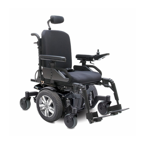
ALLIED MEDICAL Quantum Q6 Edge 2.0 User manual

ALLIED MEDICAL

ALLIED MEDICAL Quantum Q6 Edge 2.0 User manual

ALLIED MEDICAL KARMA KM8020 User manual

ALLIED MEDICAL

ALLIED MEDICAL KARMA KM8020 User manual

ALLIED MEDICAL KP25 User manual

ALLIED MEDICAL

ALLIED MEDICAL KP25 User manual

ALLIED MEDICAL Ki Mobility Catalyst 5 User manual

ALLIED MEDICAL

ALLIED MEDICAL Ki Mobility Catalyst 5 User manual

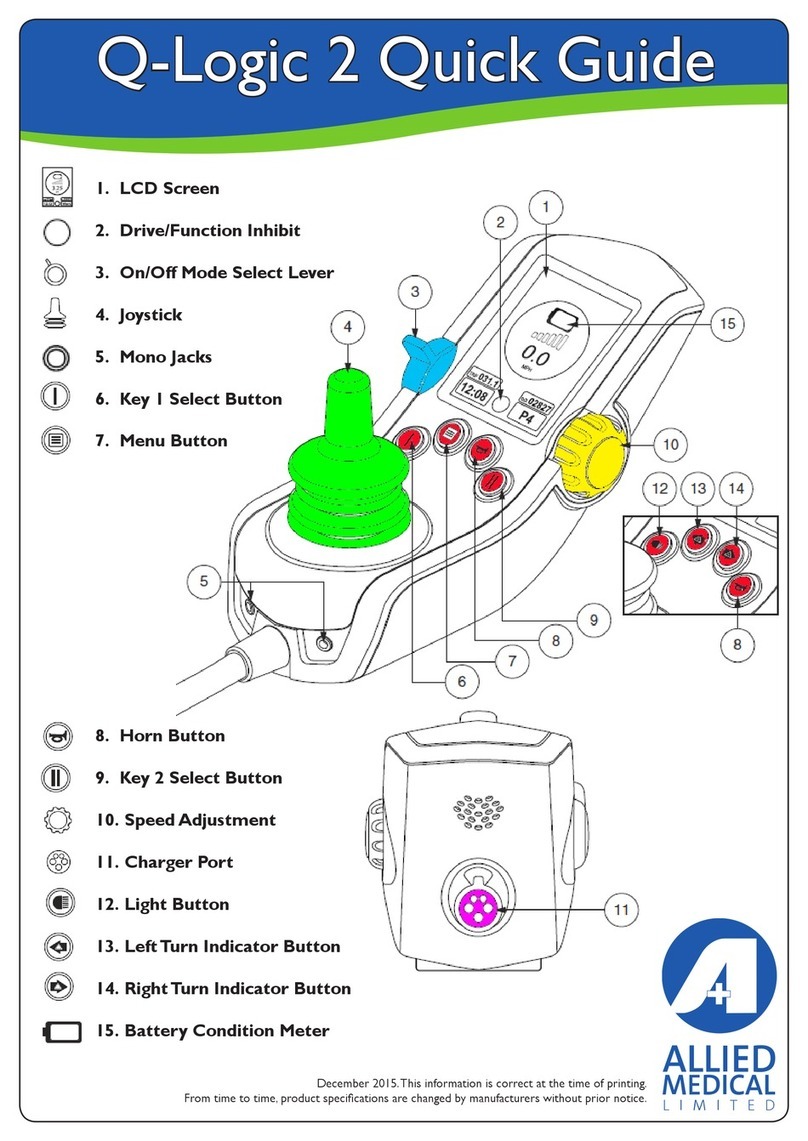
ALLIED MEDICAL Q-Logic 2 User manual

ALLIED MEDICAL

ALLIED MEDICAL Q-Logic 2 User manual

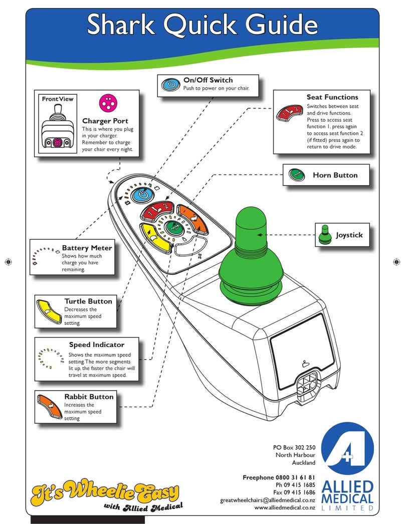
ALLIED MEDICAL Shark User manual

ALLIED MEDICAL

ALLIED MEDICAL Shark User manual

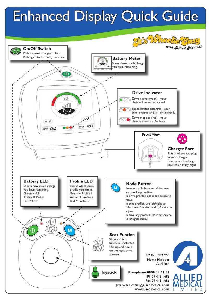
ALLIED MEDICAL Enhanced Display User manual

ALLIED MEDICAL

ALLIED MEDICAL Enhanced Display User manual

Popular Wheelchair manuals by other brands

Drive Medical Titan owner's manual

Drive Medical

Drive Medical Titan owner's manual

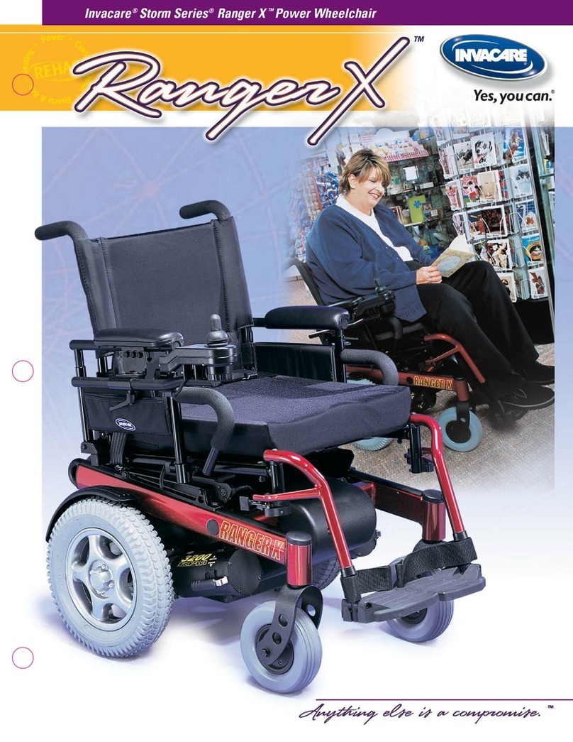
Invacare Ranger X Brochure & specs

Invacare

Invacare Ranger X Brochure & specs

Invacare Typhoon II Service manual

Invacare

Invacare Typhoon II Service manual

SHONAQUIP Madiba2go Guide

SHONAQUIP

SHONAQUIP Madiba2go Guide

Maximex Secura Premium 23546 Assembly instructions

Maximex

Maximex Secura Premium 23546 Assembly instructions

Merits P321 Series manual

Merits

Merits P321 Series manual

Küschall CHAMPION quick start guide

Küschall

Küschall CHAMPION quick start guide

Decon wheel R82 Kudu Assembly instructions

Decon wheel

Decon wheel R82 Kudu Assembly instructions

Drive Medical Super Lite manual

Drive Medical

Drive Medical Super Lite manual

Comfort Company FLEXION FOOTBOX SINGLE manual

Comfort Company

Comfort Company FLEXION FOOTBOX SINGLE manual

Merits P322 series owner's manual

Merits

Merits P322 series owner's manual

human care Leia user manual

human care

human care Leia user manual

rainbow care ZINGER user guide

rainbow care

rainbow care ZINGER user guide

Aspire Metro user manual

Aspire

Aspire Metro user manual

Stealth Products Stealth Positioning Pelvic Belts manual

Stealth Products

Stealth Products Stealth Positioning Pelvic Belts manual

Blandino SPRING Use and maintenance handbook

Blandino

Blandino SPRING Use and maintenance handbook

TGA Minimo Autofold Operating instructions and owner's handbook

TGA

TGA Minimo Autofold Operating instructions and owner's handbook

HD Rehab Motion 15680 Assembly instructions

HD Rehab

HD Rehab Motion 15680 Assembly instructions

manuals.online logo
manuals.online logoBrands
  • About & Mission
  • Contact us
  • Privacy Policy
  • Terms and Conditions

Copyright 2025 Manuals.Online. All Rights Reserved.