manuals.online logo
Brands
  1. Home
  2. •
  3. Brands
  4. •
  5. ALLIED MEDICAL
  6. •
  7. Wheelchair
  8. •
  9. ALLIED MEDICAL Quantum Q6 Edge 2.0 User manual

ALLIED MEDICAL Quantum Q6 Edge 2.0 User manual

Allied Medical Set-Up Guide
Quantum Q6 Edge 2.0
Tools required:
• Tape measure/White out pen
• Paper & Pen
• Toolbox (13mm Spanner x 2, Allen Key Set.
Phillips/Flathead Screwdriver)
• Script/Packing Slip to refer to requested build
measurements
• Velcro
• Instruction manual
1. Required measurements for set up
Letter Body Part Required (Y/N)
A Width Y
B Depth Y
C Seat to Footplate Height Y
D Backrest height Y
E Shoulder to seat Y
F Headrest
G Armrest Height RHT
G Armrest Height LFT
2. Available adjustments and options
To be clear, this is a quick set-up guide outlining the simple adjustments that can be made to get
your trial started. If there are other adjustments needed outside of what is presented in this sheet,
or the chair needs further adjustments to programming, then contact your Business Territroy
Manager and they can then either book an appointment to attend or recommend you to speak to
a sub-contractor if the chair has already been purchased.
• Changing the backrest depth involves unscrewing 2x 13mm bolts on either side of the
powerchair.
• The 13mm bolts are located on the seat rails at the rear of the powerchair seat base.
Unscrewing these bolts frees the T-nut that sits inside the seat rail to slide, thus allowing
freedom to slide back or forward to the desired position.
• Changing the backcane angle involves unscrewing 1 x 9mm screw on either side of the
powerchair. These are located on the seat rails at the rear of the powerchair seat base.
Unscrewing these bolts frees the T-nut that sits inside the seat rail to slide, thus allowing
freedom to slide back or forward to the desired position.
The measurements required may have already been taken at the initial seating assessment and or
from the initial script, but it is always good to double check before placing the client in the chair.
Depending on the time frame, from the original Assessment/Scripting to the chair set-up, things
can change.
• Check that the seat width of the chair is correct.
• Check that the chair seat depth is still correct once the backrest has been put on - remember,
if you are trialling more than 1 backrest option, the prole may not always be the same and you
may need to reduce or increase the seat depth to accommodate this.
• Check the seat to footplate measurement – this can be done while the client is positioned in
the chair. It is also a good option to have the client in foot attire, as they would most likely be
wearing shoes when using the powerchair. If the initial assessment showed leg discrepancy,
then this is a good chance to check the leg rest option can accommodate this adequately.
• Remember if you are trialling various cushions, the prole may not always be the same and
you may need to reduce or increase the footplate measurement.

Legrest/Footplate Adjustments
To change the hanger angle on the legrest (if this type is selected)
To adjust the forward/back position:
• Remove the adjustment bolt from each side rail.
• Move the legrest hanger in or out to the desired position.
• Align the adjustment holes in the legrest hanger with those in the side rail.
• Re-install the adjustment bolts to secure the legrest hangers.
To change the legrest length
• (A) Remove (loosen on swing-always) the hardware.
• Move the legrest to the desired position.
• Re-install (tighten on swing-aways) the hardware.
Change the foot plate position
• (B): Remove (loosen on swing-aways) the hardware.
• Move the footplate to the desired position.
• Re-install (tighten on swing-aways) the hardware.
To change the footplate tilt and angle on swing-aways
• (C): 1. Loosen the hardware. 2. Tilt (rotate on swing-aways) the footplate to the
desired position. 3. Tighten the hardware.
To change footplate angle
• (D): 1. Turn the setscrew(s) clockwise to decrease the angle. 2. Turn the
setscrew(s) counter clockwise to increase the angle.
Changing the Adjustable Centre-mount Foot Platform
The adjustable centre-mount foot platform is height and angle adjustable. To adjust the foot plat-
form angle:
• Remove the angle adjustment hardware from the angle adjustment bracket.
• Adjust the foot platform to the desired angle.
• Re-install the angle adjustment hardware into the angle adjustment bracket and tighten.
To adjust the foot platform height
• Loosen the height adjustment screws.
• Slide the foot platform up or down to the desired height.
• Tighten the height adjustment screws.
• Repeat on the other side if necessary.
Adjustable Centre-mount Footplate Extensions
Footplate Extensions should be already attached to the footplate when the chair arrives, if they are
not:
• For Side extensions attach by 4 x M6 Screws (Supplied) see in Fig A1
• Bell Top Extensions attach by 5 x M6 Screws (supplied)see in Fig B1
Armrest/s Adjustments
Two Post Armrest
To adjust the armrest height
• Push the spring-loaded lever inward. See gure 1.
• Move the armrest up or down to the desired height.
• Rotate the spring-loaded lever outward and lock the armrest in place. If necessary, move the
armrest up or down to ensure that the armrest is secure.
To lift up and or remove armrest
• Push the spring-loaded lever downward and pull up on the front of the armrest. See gure 2.
• Remove the detent pin from the back of the seat. See gure 3. Pull up on the rear of the
armrest to remove the assembly.
Heavy Duty Armrest
To adjust the armrest height
• Remove screws 1 and 2. See gure 1 below.
• Slide the armrest up or down the detent bar to the desired height.
• Re-install screws 1 and 2.
• Repeat for the other armrest if necessary.
• If you cannot get the desired height you may need to order detent bar 10”-14”
Drop-in Height Adjustable Armrest
To adjust the armrest height
• Push the lever down and remove the pin - see gure G1a.
• Move the armrest up or down to the desired height and replace the pin.
• To remove the drop-in armrest, see F1. Rotate the spring-loaded lever outward towards you
-you will now be able to remove the armrest for transfers.
• Once the transfer is complete, drop the armrest back into position and lock the armrest in
place.
3. Tips & Tricks
• Always remember - Lefty Loosey – Righty Tighty.
• When removing small screws or parts, have a small container handy – this stop parts from
getting lost.
• Don’t be afraid to ask any questions - we are always happy to help either by phone, video call,
Zoom or by making an appointment to set-up the client with you.
3. Checklist
What to check Done
Make sure all bolts have been re-tightened.
There are no loose straps hanging down that can get caught in the
wheels.
If you have done a client transfer from the controller side of chair,
make sure all cables are again secure and not caught anywhere.
Client is aware where the brakes are and how they work.
Client feels confident in using the chair and understands how to use
the controller. Also check their response time to lifting their hand o
the controller to stop the chair quickly .
Client understands where and how to charge the chair.
Client has contact details of a local sub contractor - technician.
If multiple carers are involved, then make sure all team members are
aware of how the chair works.

Other ALLIED MEDICAL Wheelchair manuals

ALLIED MEDICAL Varilite Icon Mid Back User manual

ALLIED MEDICAL

ALLIED MEDICAL Varilite Icon Mid Back User manual

ALLIED MEDICAL KARMA KM8020 User manual

ALLIED MEDICAL

ALLIED MEDICAL KARMA KM8020 User manual

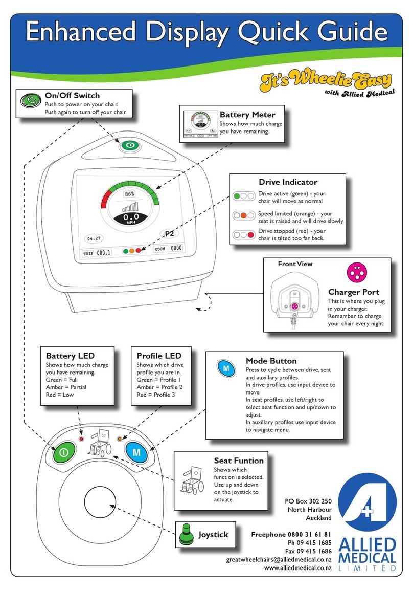
ALLIED MEDICAL Enhanced Display User manual

ALLIED MEDICAL

ALLIED MEDICAL Enhanced Display User manual

ALLIED MEDICAL Ki Mobility Rouge User manual

ALLIED MEDICAL

ALLIED MEDICAL Ki Mobility Rouge User manual

ALLIED MEDICAL Varilite Icon Deep Back User manual

ALLIED MEDICAL

ALLIED MEDICAL Varilite Icon Deep Back User manual

ALLIED MEDICAL Ki Mobility Catalyst 5 User manual

ALLIED MEDICAL

ALLIED MEDICAL Ki Mobility Catalyst 5 User manual

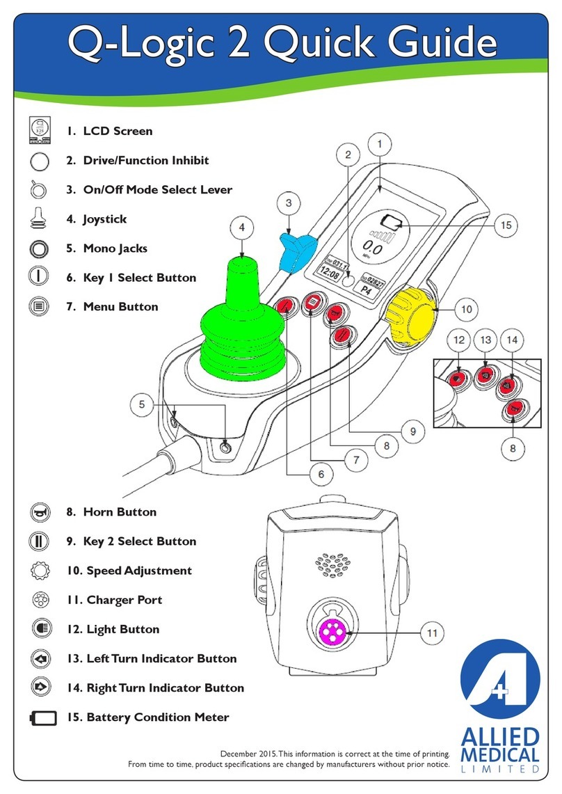
ALLIED MEDICAL Q-Logic 2 User manual

ALLIED MEDICAL

ALLIED MEDICAL Q-Logic 2 User manual

ALLIED MEDICAL KARMA 8020 User manual

ALLIED MEDICAL

ALLIED MEDICAL KARMA 8020 User manual

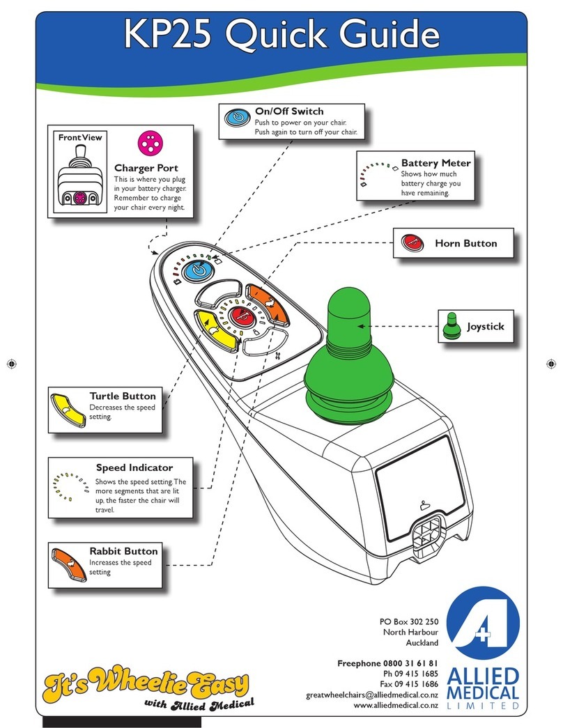
ALLIED MEDICAL KP25 User manual

ALLIED MEDICAL

ALLIED MEDICAL KP25 User manual

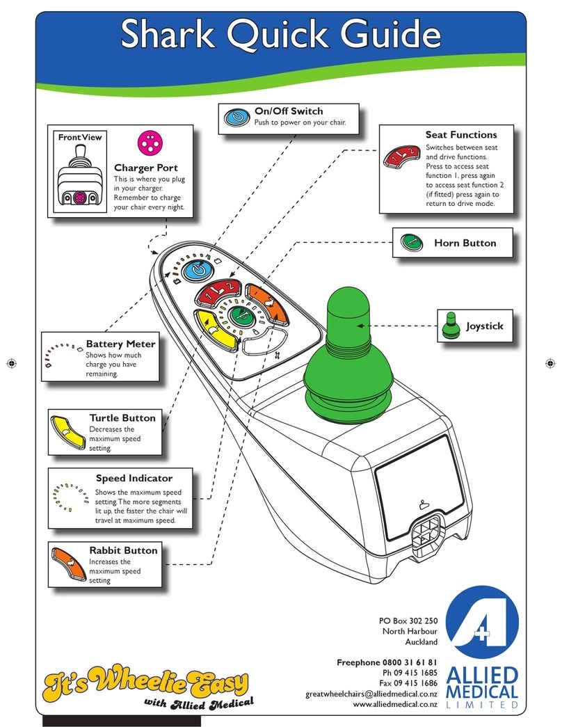
ALLIED MEDICAL Shark User manual

ALLIED MEDICAL

ALLIED MEDICAL Shark User manual

Popular Wheelchair manuals by other brands

Handicare IBIS user manual

Handicare

Handicare IBIS user manual

Neatech JOB User and maintenance manual

Neatech

Neatech JOB User and maintenance manual

Invacare Action 4NG series user manual

Invacare

Invacare Action 4NG series user manual

Nova TKW-12 user guide

Nova

Nova TKW-12 user guide

Drive Medical Titan owner's manual

Drive Medical

Drive Medical Titan owner's manual

Autoadapt Carolift 40 user manual

Autoadapt

Autoadapt Carolift 40 user manual

Excel Mobil user manual

Excel

Excel Mobil user manual

Valex M-MU 18-MULTI ONE instruction manual

Valex

Valex M-MU 18-MULTI ONE instruction manual

Sunrise Medical Guardian Escort User instruction manual & warranty

Sunrise Medical

Sunrise Medical Guardian Escort User instruction manual & warranty

Invacare Ranger X Brochure & specs

Invacare

Invacare Ranger X Brochure & specs

REA Clematis Service manual

REA

REA Clematis Service manual

Vicair VECTOR O2 Important notice

Vicair

Vicair VECTOR O2 Important notice

Küschall K-SERIES Service manual

Küschall

Küschall K-SERIES Service manual

dynarex DynaRide 10233 manual

dynarex

dynarex DynaRide 10233 manual

Monarch Ezi-Fold D10 operating manual

Monarch

Monarch Ezi-Fold D10 operating manual

Quickie One-Arm Drive Quickie 2 owner's manual

Quickie

Quickie One-Arm Drive Quickie 2 owner's manual

R82 Wombat Living 1 user guide

R82

R82 Wombat Living 1 user guide

GRIT GRITJunior Assembly guide & user's manual

GRIT

GRIT GRITJunior Assembly guide & user's manual

manuals.online logo
manuals.online logoBrands
  • About & Mission
  • Contact us
  • Privacy Policy
  • Terms and Conditions

Copyright 2025 Manuals.Online. All Rights Reserved.