Allied Systems Freeman 370 Installation and operating instructions

Sidefeed Gearbox Baler, 3-Tie
OPERATOR’S AND PARTS ADDENDUM
A Product of
Sherwood, Oregon USA
89-096 S/N: STARTING WITH S/N 375E21G032
Important: Be certain to specify the
serial number of your Baler when
ordering parts.

Contents
Safety.............................................................................................. 3-7
Serial Number Location ..................................................................... 9
Maintenance .................................................................................... 10
Gearbox Baler Parts ........................................................................ 11
Front End Installation, Gearbox 37X................................................ 12
. Front End Assembly, Gearbox 37X ........................................... 14-15
Engine Installation, Gearbox 37X ............................................... 16-19
. Engine Assembly, Tier 4-Interim, Gearbox 37X ........................ 20-23
. Air Cleaner Assembly..................................................................... 24
Gearbox Installation, 16” Chamber ............................................. 26-30
Gearbox Installation,(37X) 15” Chamber .................................... 31-35
Gearbox Installation,(37X) 14” Chamber .................................... 36-40
Gearbox Installation,(37X) 14” X 21” Chamber........................... 41-45
Gearbox ...................................................................................... 46-47
Knotter Drive Installation, Gearbox Baler ................................... 48-49
Shield Installation, LH...................................................................... 50
Shield Installation, Crank Arm ......................................................... 51
Plunger Assy, 16”x22”................................................................. 52-55
Plunger Assy, Kittted for 15”x22” ................................................ 56-59
Plunger Assy, Kittted for 14”x22” ................................................ 60-63
Plunger Assy, Kitted for 14”x21” ................................................. 64-66
Connecting Rod Assy, Gearbox Baler, 15/16” 3-Tie ....................... 67
Connecting Rod Assy, Gearbox Baler, 14” 3-Tie ............................ 68
Tensioning/Rear Mnt Inst, 37X - 16” ........................................... 69-72
Tensioning/Rear Mnt Inst, 37X - 16” Ktd - 15”............................. 73-76
Tensioning/Rear Mnt Inst, 37X - 16” Ktd - 14”............................. 77-80
Tensioning/Rear Mnt Inst, 37X - 16” Ktd - 14”x21”...................... 81-84
Tensioning/Rear Mnt Inst - 380/385, 14” Kitted .......................... 85-86
Frame & Axle, 16” ........................................................................... 87
Frame & Axle, 14 X 21” ................................................................... 88
Chamber Inst, 14x21 Gearbox 3 Tie .......................................... 86-95
Chamber Installation Gearbox 3 Tie 14x22,15x22,16x22 ........ 96-106
See alliedsystems.com for our most current documents.
2
89-096 Rev: 11-2016

389-096Rev: 11-2016
Safety
General
The following pages contain general safety warnings
which supplement specific warnings and cautions ap-
pearing elsewhere in this manual. All electrical and
hydraulic equipment is potentially hazardous. You must
thoroughly review and understand this Safety Section
before attempting to operate, troubleshoot, maintain or
service this baler.
Time, money and effort have been invested in making
your Baler a safe product. The dividend from this invest-
ment is YOUR PERSONAL SAFETY.
However, it must be realized that no power-driven equip-
ment can be any safer than the person behind the con-
trols. If you don’t operate and maintain your Freeman
Baler safely, our efforts will have been in vain.
The safety instructions and warnings, as documented
in this manual and shipped with the machine, provide
the most reliable procedures for the safe operation and
maintenance of your Baler. It’s your responsibility to see
that they are carried out.
Allied Systems Company cannot anticipate all worksite
conditions, local regulations, etc. It is the responsibil-
ity of the end user to be aware of and obey any specific
worksite, local, state, or national regulations or proce-
dures that are applicable to operating this baler.
NOTE: All possible safety hazards cannot be antici-
pated so as to be included in this manual. Therefore,
you must always be alert to potential hazards that
could endanger personnel and/or damage the equip-
ment.
Safety Symbols
The following symbols/terms are used to emphasize
safety precautions and notices in this manual:
DANGER
The “DANGER” symbol indicates a hazardous
situation which, if not avoided, will result in
death or serious injury. Carefully read the mes-
sage that follows to prevent serious injury or
death.
WARNING
The “WARNING” symbol indicates a hazardous
situation which, if not avoided, could result in
death or serious injury. Carefully read the mes-
sage that follows to prevent serious injury or
death.
CAUTION
The “CAUTION” symbol indicates a hazardous
situation which, if not avoided, could result in
minor or moderate injury, or equipment dam-
age. Carefully read the message that follows to
prevent minor or moderate injury.
NOTICE
The “NOTICE” symbol alerts to a situation that is not
related to personal injury but may cause equipment
damage.
NOTE: …
The term “NOTE” highlights operating procedures or
practices that may improve equipment reliability and/or
personnel performance, or to emphasize a concept.
Intended Use Statement:
This baler is intended to gather and compress
loose, fibrous material (i.e., hay) and form it
into rectangular bales. Use in any other way is
considered to be contrary to the intended use.
If you are unsure of the material you intend to
bale, consult the factory.

4
89-096 Rev: 11-2016
Operation Warnings
WARNING
Failure to observe the following safety rules may
result in extreme personal injury, dismember-
ment or death. It is the operator’s responsibility
to understand the proper and safe use of this
baler.
• Make sure that you read, understand, and obey all of
the safety precautions and operating instructions in
this Operator’s Manual.
• Keep this Operator’s Manual and the Safety Card
(Allied form #89-028) with the baler at all times.
• Do not operate the baler unless you are authorized
and trained to do so. If it has been some time since
you last operated the baler, re-familiarize yourself
with the baler before starting, then proceed slowly.
• Do not operate the baler if you are aware of any mal-
functions, needed maintenance or repairs.
• Stop the baler immediately if any problems arise.
• Never allow others to ride on the baler.
• Never allow anyone with-
in 10 ft of the baler while
the baler is in operation.
• Never operate the baler
without all safety shield-
ing in place.
• Keep hands, feet, hair,
jewelry and clothing
away from moving parts,
including but not limited
to the pickup, knotter,
and PTO shaft.
• Avoid wearing loose
clothing which can eas-
ily be caught in moving
parts.
• Use appropriate signs (i.e., Slow Moving Vehicle
sign), signals or warning lights when transporting on
highways.
• Always use lights when working at night or in low
light conditions.
• Know your job-site rules. Some have site specific
directions and procedures. The methods outlined in
this manual provide a basis for safe operation of the
baler. Because of special conditions, your com-
pany’s baling procedures may be somewhat different
from those shown in this manual.
• Do not start the tractor if the key had been marked
with a “DO NOT START” or “RED” tag.
• Never operate any of the tractor’s controls from any-
where other than the operator’s seat.
• Alert personnel in the area before starting the en-
gine, and make sure everyone is clear. Be sure that
all controls are in neutral and the baler is disen-
gaged before starting the engine.
• Each country has its own safety legislation. It is in
the operator’s own interest to be conversant with
these regulations and to comply with them in full.
This also applies to local bylaws and regulations in
force on a particular worksite.
• Should the recommendations in this manual deviate
from those in the user’ country, the national regula-
tions should be followed.
• Never attempt to disconnect any of the safety de-
vices built into the baler or tractor.
• Maintain proper clearance from energized equip-
ment, energized power lines or other power sources.
High voltage electricity can discharge to ground with-
out direct contact with the baler’s or tractor’s struc-
ture. If the baler or tractor contacts energized equip-
ment, or if electrical energy does discharge through
the machine—stay clear, and prevent anyone else
from coming in contact with the baler or tractor. If
you are on the tractor, stand fast, avoid contact with
metal surfaces, and do not permit anyone to come
into contact with the tractor or baler. Finally, Do not
jump off.

589-096Rev: 11-2016
Hydraulic Hazards
Be aware of the hazards of pressurized hydraulics:
• Wear personal protective equipment, such as gloves
and safety glasses, whenever servicing or checking
a hydraulic system.
• Assume that all hydraulic hoses and components are
pressurized. Relieve all hydraulic pressure before
disconnecting any hydraulic line.
• Never try to stop or check for a hydraulic leak with
any part of your body; use a piece of cardboard to
check for hydraulic leaks.
• Small hydraulic hose leaks are extremely dangerous,
and can inject hydraulic
oil under the skin, even
through gloves.
• Infection and gangrene
are possible when
hydraulic oil penetrates
the skin. See a doctor
immediately to prevent
loss of limb or death.
Maintenance Safety
• Perform all routine maintenance outlined in this Op-
erator’s Manual in the time intervals indicated.
• Maintenance, lubrication and repair of this machine
can be dangerous unless performed properly. In
order to ensure safety, each person working on this
baler must have the necessary skills, information,
tools and equipment, and satisfy himself that his
work method is safe, correct, and meets his own
company’s requirements.
• Do not attempt to make adjustments, or perform
repairs unless you are authorized and qualified to do
so.
• Never attempt to service energized equipment.
• Do not rely on the hydraulic system to support any
part of the baler during maintenance or lubrica-
tion. Never stand under a baler component that is
supported only by the hydraulic system. Ensure
components are resting on their mechanical stops
or supported with appropriate safety stands during
maintenance or lubrication.
• Never attempt servicing while the baler is moving.
Shut off the tractor and secure power.
• Shut off tractor and baler engine, engage the parking
brake, disengage the baler, and wait for all move-
ment to stop before adjusting, lubricating, cleaning,
or servicing the baler.
• Tag the key switch with a ”DO NOT START” sign
and/or remove the key.
• Always perform all maintenance and lubrication
procedures with the baler on level ground, parked in
a safe area.
• Block the tires to keep the machine from rolling.
• Any unauthorized modifications made to the baler
by the customer or parties other than Allied Systems
will relieve Allied Systems Company and your Free-
man dealer of any liability for damage or injury.
• Replace any worn parts only with genuine Freeman
parts. Call your dealer for assistance.
• Unless specified in service procedures, never at-
tempt maintenance or lubrication procedures while
the baler is moving or the engine is running.
• Engine exhaust fumes
can cause death. If it
is necessary to run the
engine in an enclosed
space, remove the
exhaust fumes from the
area with an exhaust
pipe extension. Use
ventilation fans and open
shop doors to provide
adequate ventilation.
• DO NOT remove the ra-
diator cap when the en-
gine is hot. The coolant
will be under pressure
and can flash to steam
with explosive force,
causing severe burns. To
prevent burns, remove
the radiator cap only
when the engine is cool.
• Batteries contain sulfuric acid which can cause se-
vere burns. Avoid contact with skin, eyes or clothing.

6
89-096 Rev: 11-2016
• Batteries produce explo-
sive gases. Keep sparks,
flame and cigarettes
away. Ventilate when
charging or servicing
in an enclosed space.
Always shield your eyes
when working near bat-
teries. When removing
battery cables, disconnect the negative (-) cable
first. When installing a battery, always connect the
positive (+) cable first. This procedure will help to
prevent a spark which could cause an explosion.
• Before making adjustments to the engine or chassis
electrical system, disconnect the battery. An elec-
trical spark could cause a fire, explosion or severe
burns.
Safety Equipment
• Ensure test equipment is in good condition.
• If an instrument must be held while taking measure-
ments, ground the case of the instrument before
energizing equipment.
• Do not touch live equipment or personnel working
on live equipment while holding a multimeter. Some
types of measuring devices should not be ground-
ed—do not hold such devices while taking measure-
ments.
• Prevent personal injury or equipment damage by us-
ing a lifting device with a lifting capacity greater than
twice the weight of any equipment to be lifted.
• Always use personal protective equipment (PPE) ap-
propriate to the situation. This may include the use
of hearing protection, eye protection, a respirator, a
hard hat, leather gloves, steel toed boots, etc.
Electrical Hazards
• An electric shock could
be fatal. Ensure power to
the baler is “OFF” before
opening electrical panels.
• All electrical cables and
connectors must be in
good condition (free
of corrosion, damage,
etc). Use caution in wet
weather to avoid danger
from electrical shock.
Never attempt electrical
testing or repair while
standing in water.
• Do not wear electrically
conductive jewelry, cloth-
ing, or other items while working on the electrical
system.
Hot Oil Hazards
• Burns from hot oil can be severe—Always allow
lubricating and hydraulic oil to cool before draining.
Compressed Air Hazards
• When using compressed air to dry parts, pressure
should not exceed 30 psi (200 kPa).
• Air pressure penetrating your skin can be fatal.
Never direct compressed air at anyone.

789-096Rev: 11-2016
Fire Safety
WARNING
Diesel fuel and hydraulic oil are flammable.
Never smoke while handling fuel or working on
the fuel system. The fumes in an empty fuel
container are explosive. Never cut or weld on or
near fuel lines, tanks, or containers. Keep open
flames and sparks away from the machine.
Reduce the Risk of Fire
• Keep the baler free of oil,
grease, hay, and trash
accumulations. Regular
cleaning is recommend-
ed for fire prevention
and general safety. Use
an approved solvent to
clean machine parts.
Never use gasoline or
diesel fuel.
• Shut off the engine and electrical equipment while
filling the fuel tank. Use extra caution when fueling a
hot engine. Always ground the fuel nozzle against
the filler neck to avoid sparks.
• Never overfill the fuel or hydraulic tanks. Any
overflow could cause a fire. Immediately repair any
hydraulic or fuel leaks and clean up any spills.
• Handle all solvents and dry chemicals according to
procedures identified on manufacturer’s containers.
Work in a well-ventilated area. Make sure you know
where fire extinguishers are kept and how to use
them.
• Avoid spilling fuel or other hazardous liquids. If
a spill occurs, follow local or state regulations for
clean-up. Contact your state’s OSHA office for
details.
• Always ensure that excess grease and oil accumula-
tion, including spillage, is cleaned up immediately.
• Inspect the baler daily for potential fire hazards and
make any necessary repairs immediately.
• Check all the electrical wiring and connections for
defects, and repair or replace as necessary. Keep
battery terminals clean and tight.
• Never perform welding operations until the entire
machine has undergone a thorough cleaning. In
addition, cover rubber hoses, disconnect the battery,
and have at least a fire extinguisher at hand.
• Hydraulic fluid is flammable. Do not weld on or near
pipes, tubes, or hoses that are filled with fluid. Do not
smoke when checking or filling the tank. Keep open
flames and sparks away from the baler.
• Hay dust is combustible. Do not have an open flame
or weld in dusty environments.
• Maintain the engine cooling system to avoid over-
heating.
• Remember, there is always a risk of fire.
Fire Fighting Equipment
• It is recommended to carry an “ABC” fire extin-
guisher on the baler or in the pull vehicle at all times.
Install it within easy reach of the operator in a posi-
tion that protects it from damage. Use only a “quick
release” type of mount. It is also recommended to
carry a four gallon water container with a pump, or
as required by local and state law.
• Keep your fire extinguisher(s) fully charged and in
good working order. Know how to use them.
• Read and understand the instructions printed on the
canisters and learn how to operate them. Learn how
to remove the canisters from their mounting brackets
in the shortest amount of time.
• Service the extinguisher according to the manufac-
turer’s specifications. Service after every use, no
matter how short a time.
Fire Suppression
• Do not panic. At the first sign of trouble (burning
smell, smoke, visible flame, etc), stop the tractor and
turn off the engine in the clearest area available, with
the tractor upwind from the baler if possible.
• If the fire cannot be extinguished safely, immediately
evacuate the area. DO NOT attempt to extinguish it.
DO NOT risk personal injury. Contact your local fire
department.
• If you have determined that the fire may be safely
extinguished, use the fire extinguisher according
to the manufacturer’s instructions, or use the water
pump, aiming water at the base of the fire.
• When the baler has fully cooled, thoroughly inspect,
and make all necessary repairs to return the baler to
normal operation.
• Recharge or replace the extinguishers before return-
ing to work.

Intentionally Left Blank
8
89-096 Rev: 11-2016

Serial Number Location
Each Freeman Baler is identified by means of a baler model number and baler serial number. As a further identifica-
tion, all power units are provided with a serial number. The serial number is an important piece of information about
the machine and it may be necessary to know it before obtaining the correct replacement part. The serial number
is located on the top chamber rail on the rear left-hand side, above the tool box. To ensure prompt, efficient service
when ordering parts or requesting repairs from your authorized Freeman dealer, record the serial numbers in the
spaces provided.
Baler Serial Number
Rear, left side of baler on upper frame.
Power Unit Serial Number
Deutz Diesel - forward side of engine on block.
Driveline P.T.O. 540 RPM - top of gearbox.
NOTE: Reference to left-hand and right-hand used throughout the manual are understood to mean from a posi-
tion facing in the direction of travel.
Side Feed Baler Serial Number Format
As Of 2011
3 8 5E16-12 3
Drive Type
E - Engine
H - Hydro
D - Driveline
S - Self Propelled
Plunger Size
14”, 15”, 16”
Sequential
Number
Twines/Bale
2 - 2-Tie
3 - 3-Tie
Knotter
0 - Conventional
5 - Tailless
Model
7 - Base
8 - Premium
Dash - Bullgears
G - Gearbox
Serial Number Location
989-096Rev: 11-2016

WARNING
Chock baler wheels to prevent baler from mov-
ing and make sure baler and tractor are both
turned off and all moving parts have come to a
complete stop before starting any maintenance.
Contact with moving equipment can cause seri-
ous injury or death.
Use Mobilube HD Plus 80W-90 Gear Oil, Allied P/N
235720.
Check oil level daily:
With the baler sitting level, remove the fill/check plug. Oil
should be level with the bottom of the opening (see Fig-
ure 2.) Add oil as necessary through the same opening.
Replace plug and tighten securely.
Change oil after first 50 hours, then every 250 hours:
1. Place a catch pan beneath the gearbox, under the
drain plug.
2. Remove the drain plug from the bottom of the gear-
box (see Figure 2) and let oil drain into catch pan.
3. Replace the drain plug.
4. Add new oil through the fill/check plug opening until
the oil is level with the bottom of the opening (see
Figure 2.) Replace plug and tighten securely.
5. Dispose of used oil in accordance with local regula-
tions.
Check Bolts on Crank Arm Every 3 months/125
hours/25,000 bales, whichever comes first
(see Figure 1).
1. Torque the
four (4)
retaining cap
bolts to
340 ft-lbs.
2. Torque the
one (1)
clamp bolt
to 750-755
ft-lbs.
Maintenance
Fill/Check Plug
Drain Plug
Figure 2 - Gearbox
Connecting Rod/Crank Arm:
Grease the connecting rod bushing daily until you just
see grease emerging from around the bushing (see
Figure 3).
Grease the gearbox crank arm bearings at the beginning
of every season, and then every 50 hours (see Figure 3).
Figure 3 - Gearbox Lubrication (Top View)
Gearbox Crank
Arm Bearing
Grease Fitting
Connecting
Rod Bushing
Grease Fitting
4 Retaining Cap Bolts
340 Ft-Lbs
1 Clamp Bolt
750-755 Ft-Lbs
Figure 1 - Crank Arm Torque
10
89-096 Rev: 11-2016

This section contains all components of the Gearbox
baler that are not included in the standard Engine/
Hydro Parts Manual. This includes all parts that can
be separately identified as well as parts necessary for
equipment support.
Illustrations
Illustrations are provided whenever possible to rep-
resent component parts and the mounting location of
those parts. The numbered labels correspond to the
item numbers in the parts list.
Parts Lists
Component parts lists are presented in a 5-column
format:
Item: Index numbers found in this column correspond
to the numbers found on the respective parts loca-
tion illustration. Some items are shown for reference
purposes only to illustrate their relationship to other
systems.
Notes: This column identifies footnotes applicable to
specified items.
Part Number: This column lists the Allied Systems
Company Part Number.
Quantity: This column lists the total number of a
specific item required per assembly or subassembly.
This number may not necessarily be the number of
items used in the end item or system. Only one set of
components is listed whenever the components of two
assemblies are the same.
“A/R” (as required) identifies bulk items whose
length or other dimension must be specified when
requisitioning.
“Ref” identifies items shown for reference purposes
only to illustrate their relationship to other systems.
“NSS” (not sold separately) identifies items such as
valve housings and spools, ring gears and pinions,
etc., which must be ordered as a set because they
are closely mated at manufacture.
Description: This column lists the item nomenclature
along with those modifiers necessary to identify the
item. Additionally, cross references for repairable sub-
assemblies are listed in this column. One dot preced-
ing the description indicates that the item is a compo-
nent part of the previously listed item or assembly with
no dot. Two dots indicate that the item is part of the
previously listed item with one dot.
Example:
Engine Installation
. Engine Assembly
. . Manifold Assembly
. . Control Box Assembly
. . . Module Assembly
The Engine Assembly is a first level subassembly of
the Engine Installation as indicated with one dot. The
Manifold Assembly and the Control Box Assembly are
second level components of the Engine Assembly as
indicated by the two dots. The Module Assembly is a
third level component of the Control Box Assembly
which is indicated with three dots.
Gearbox Baler Parts
11 89-096Rev: 11-2016

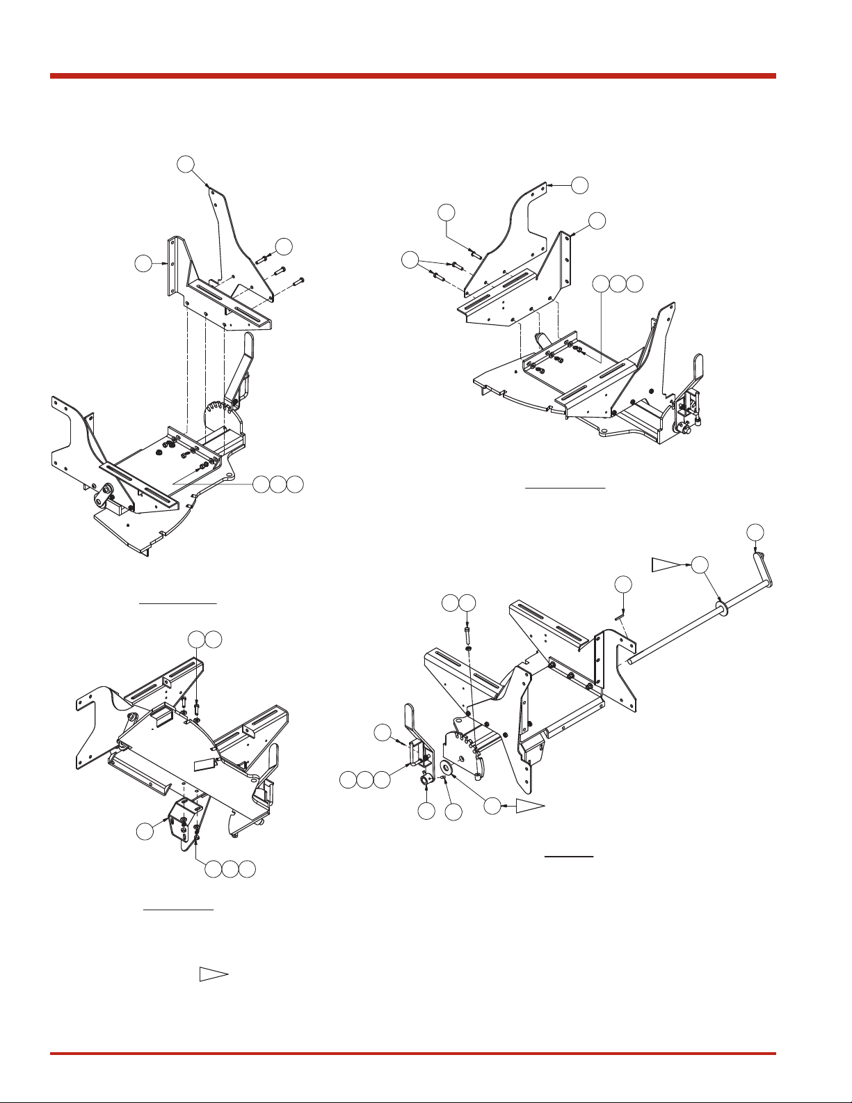
Front End Installation, Gearbox 37X
Page 1 of 1
Front End Installation, Gearbox Baler
Page 1 of 1
Item Part No. Qty Description Item Part No. Qty Description
906814 Installation, Front End
1 * 906815 1 . Front End Assembly
2 R13806345 2 . Capscrew
3 221771W 10 . Hard Washer
4 R13812516 18 . Lockwasher
5 221712W 8 . Hex Nut
6 Y25G-0824 2 . Capscrew
7 200454W 8 . Capscrew
8 221711W 8 . Hex Nut
9 234176 6 . Capscrew
* See Separate Coverage
Rev B
9 5 4 3
784
684
7
34
2X
8 4 7
X2
847
X2
5439
3X
2X
2X
1
X3
2
4
5
3
2X
12
89-096 Rev: 11-2016

Intentionally Left Blank
13 89-096Rev: 11-2016
Front End Assembly, Gearbox 37X
Page 1 of 2
Front End Assembly
Page 1 of 2
RH MOUNT
LH MOUNT
LEVER
BRACKET
24
7
19 18 14
8
X3
3X
13
24
19 18 14
4
6
X3
12 14
19 18 14
11
2X
X2
9
22
21
2317
115
X2
5
1620
5
NOTES:
- USE WASHERS (ITEM 5) AS NEEDED TO LIMIT SIDE-TO-SIDE MOVEMENT, BUT STILL ALLOW LEVER TO ROTATE FREELY.
1-1
1-1
1-1
14
89-096 Rev: 11-2016

Front End Assembly, Gearbox 37X
Page 2 of 2
Item Part No. Qty Description Item Part No. Qty Description
906815 Front End Assembly
1 F000007539 1 . Lever Weldment
2 F000007540 1 . Pin, Lift Lever Adj
3 F000007541 1 . Compression Spring
4 906822 1 . Engine Mounting Weldment, RH
5 F000008247 2 . Washer
6 GUS0024467 1 . Plate,Support Gusset
7 904463 1 . Plate,Support
8 906824 1 . Engine Mounting Weldment, LH
9 PLF0026952 1 . Lever Weldment
10 906825 1 . Hitch Base Weldment
11 904477 1 . Plate, Front Gusset
12 221569W 2 . Capscrew
13 Y25G-0832 1 . Capscrew
14 221771W 10 . Hard Washer
15 SQS3750750 2 . Square Head Screw
16 SQS5003000 1 . Screw, Set
17 223634 1 . Flat Washer
18 R13812516 8 . Lockwasher
19 221711W 8 . Hex Nut
20 234218 1 . Jam Nut
21 15223W 1 . Pin, Cotter
22 48688 1 . Key
23 11079 1 . Fitting, Lube
24 R13811077 5 . Capscrew
Rev -
Front End Assembly
Page 2 of 2
10
23
15 89-096Rev: 11-2016

Engine Installation, 37X
Page 1 of 4
Engine Installation, 37X
Page 1 of 4
Item Part No. Qty Description Item Part No. Qty Description
906189 Engine Installation
1 * 906188 1 . Assembly, Engine
2 252293 1 . Muffler
3 F000007742 1 . Battery Ground Strap 12 Volt
4 CLP0035751 1 . Clamp, Exhaust
5 EXH0011007 1 . Cap, Exhaust
6 F000007010 2 . Bolt, Adjusting
7 253403 1 . Gauge
8 F000007000 1 . Belt, Drive
9 * 254896 1 . Air Cleaner Assembly
10 ACL0004307 2 . Band, Air Cleaner
11 207146 3 . T-Bolt Clamp
12 207147 1 . T-Bolt Clamp
13 225370 2 . T-Bolt Clamp
14 ACL0000005 1 . Insert, Rubber
15 4200115 1 . Elbow, Rubber
16 255118 1 . Reducer
17 255120 1 . Reducer
18 00273802 4 . Nut, Serrated
19 SMS0000184 4 . Bolt, Whiz
20 902789 1 . Plate
21 252742 1 . Precleaner
22 ACL0000004 1 . Indicator
23 902904 1 . Tube, Spacer
24 902909 1 . Elbow
25 902913 1 . Tube
26 221569W 2 . Capscrew
27 234665 4 . Lockwasher
28 221771W 14 . Hard Washer
29 221711W 8 . Hex Nut
30 221576W 2 . Capscrew
31 HYD5275032 1 . Connector, Bulkhead
32 399741W 2 . Screw, Flange
33 R13812213 2 . Flat Washer
34 09416918 2 . Nut, Serrated
* See Separate Coverage
N/A Not Applicable
Rev - AA
NOTES:
1-1 ENSURE 84 TO 86 PLUNGER STROKES PER MINUTE
AT ENGINE FULL THROTTLE.
1-2 ENSURE 33 TO 35 PLUNGER STROKES PER MINUTE
AT ENGINE LOW IDLE.
1-3 906189 ASSY SHOWN
16
89-096 Rev: 11-2016

Engine Installation, 37X
Page 2 of 4
Engine Installation, 37X
Page 2 of 4
FLYWHEEL BELT MOUNTING
BELT SHIELD NOT SHOWN
370/375 BALER SHOWN
BATTERY STRAP & CABLE MOUNTING
370/375 BALER SHOWN
DETAIL A
1
8
RED 12 GA WIRE
FROM CONTROL BOX
HARNESS
3
NEG
POS
REFERENCE EXISTING BATTERY
CABLE ON ENGINE ASSEMBLY
2-2
2-1
A
REFERENCE
#BAT0277000
12V BATTERY
2-4
2-3
REFERENCE
EXISTING BATTERY
CABLE ON ENGINE
ASSEMBLY
RECOMENDED BELT TENSION
BELT DEFLECTION FORCE
F000007000 0.75" 16 LB
256812 0.63" 16 LB
2-1
17 89-096Rev: 11-2016

Engine Installation, 37X
Page 3 of 4
Engine Installation, 37X
Page 3 of 4
ENGINE BELLY PAN
TO FRONT END
ASSY. MOUNTING
29 27 28
29 27 28 28
29
27
28
28
30
28
28
26
28
28
30 28 28
26 28 28
629 29
27
28
NOTES:
MOUNT BATTERY GROUND CABLE TO
THIS FASTENER ON THE ENGINE.
GEARBOX BALER ONLY:
ROUTE GROUND WIRE BEHIND ENGINE TO BATTERY.
SEE TABLE FOE RECOMENDED BELT DEFLECTION
AND DOWNWARD FORCE AT CENTER OF BELT SPAN.
FOR GEARBOX BALER ENSURE ENGINE PUMP IS PRIMED PRIOR
TO STARTING ENGINE. CAN FILL HYDRAULIC RESERVOIR AND
LET SIT FOR 8 HRS TO PRIME PUMP.
906189 ASSY SHOWN.
2-1
2-2
2-3
2-4
2X 2X
2-5
18
89-096 Rev: 11-2016

Engine Installation, 37X
Page 4 of 4
Engine Installation, 37X
Page 4 of 4
MUFFLER AND TENSION CONTROL
370/375 BULLGEAR BALER SHOWN
AIR CLEANER ASSEMBLY
5
2
4
1
31
7
AIR CLEANER ASSEMBLY
14
13
15
11
23
11
24
11
22
9
16
12
17
13
25
21
20 18 19
10
1
32
32
34 33
34 33
REFER TO 906705 FOR ADDITIONAL
AIR CLEANER ASSEMBLY NOTES
AIR CLEANER MOUNT
LOCATION ON SNORKEL
USE EXISTING HARDWARE
19 89-096Rev: 11-2016

Engine Assembly
Page 1 of 4
In Baler Parts Manual
Engine Assembly
Page 1 of 4
Item Part No. Qty Description Item Part No. Qty Description
906188 Assembly, Engine
1 * 903907 1 . Control Box Assembly
2 CBL1743180 1 . Cable, Control
3 CLH0001084 1 . Clutch
4 CLV1756012 1 . Clevis Assembly
5 * 258766 1 . Engine, Deutz 4 Cylinder
6 900537 1 . Arm Extension Weldment
7 EXH0013806 1 . Tube, Exhaust
8 900534 1 . Plate,Mounting
9 F000007699 1 . Pulley, Motor
10 MNT0018340 1 . Belly Pan Weldment
11 F000007013 1 . Bracket
12 252601 2 . Fitting
13 231486 1 . Set Screw
14 STS5000750 1 . Set Screw
15 SHD0028273 1 . Plate,Shield
17 R13811085 4 . Capscrew
18 Y09C-M0616 1 . Capscrew
20 Y09C-M1030 22 . Capscrew
25 221771W 8 . Washer
26 234589 22 . Lockwasher
27 292680W 1 . Washer
28 296420W 18 . Hard Washer
29 220044 1 . Hex Nut
32 223587 4 . Nut, Esna
33 235620 2 . Nut, Esna
37 R13810989 2 . Capscrew
38 R13811014 2 . Capscrew
39 232939 2 . Nut, Esna
40 905246 16 . Washer, Fender
41 904697 1 . Restrictor
42 201431 1 . Hose Clamp
43 CBL0000126 1 . Cable Assembly,Battery
44 906659 1 . Fitting
45 906660 1 . Hose Assembly
46 236077 3GL . Oil, Engine
47 293613W 1 . Capscrew
48 WLKM000080 1 . Lockwasher
49 WCTM100080 1 . Washer
50 209588 1 . Clip
* See Separate Coverage
Rev A
9
NOTES:
AFTER INSTALLING PULLEY CUT AWAY EXCESS SHAFT FROM
CLUTCH. REMAINING SHAFT SHOULD EXTEND PAST PULLEY
APPROXIMATELY 0.25".
TRIM SIDE CONNECTING TAB BEFORE TAPING.
SET FINAL TOP ENGINE RPM AT FULL THROTTLE TO 2200 TO 2250
(84 TO 86 PLUNGER STROKES PER MINUTE).
SET FINAL LOW ENGINE RPM AT FULL THROTTLE TO 1000 TO
1025 (33 TO 35 PLUNGER STROKES PER MINUTE).
ALL MEASUREMENTS ARE TO BE TAKEN AT THE PULLEY OFF
THE ENGINE. REFER TO ENGINE ASSEMBLY NOTES (ITEM 0, PN
906640) FOR MORE DETAILED INSTRUCTIONS.
1-1
1-1
RED / WHITE
16 GA WIRE
RED YELLOW
WHITE
WHITE
CONNECT TO ENGINE WIRE
HARNESS, THEN TAPE
CONNECTORS TOGETHER.
WIDE TAB
NARROW TAB
TEMP SENSOR
CONNECT WIRE END
TO NARROW TAB.
ENGINE HARNESS
1-2
1-2
1-2
1-3
1-4
1-5
20
89-096 Rev: 11-2016
Table of contents


