AgLand Macerator 6600 User manual

Assembly Instructions
Operators Manual
Parts Catalog
Macerator 6600™

INTRODUCTION PAGE 3
SAFETY PRECAUTIONS PAGE 4
SPECIFICATIONS PAGE 5
ASSEMBLY PAGE 6 - 8
TRANSPORT PAGE 9
OPERATION PAGE 10 -13
MAINTENANCE PAGE 14 -16
LUBRICATION PAGE 17
AIR SYSTEM PAGE 18
HYDRAULIC SYSTEM PAGE 18
TROUBLE SHOOTING PAGE 19 - 20
PARTS LISTS - MAIN UNIT PAGE 22 - 33
ATTACHMENTS PAGE 34 - 37
WARRANTY BACK COVER
Replacement Parts
To obtain prompt, efficient service, always
remember to give the dealer the following
information:
1. Correct part description
2. Model number of the machine
3. Serial number of the machine
The serial number is important in identifying your
machine. It contains information for ordering
replacement parts and options, which may vary,
depending on the serial number identification.
(Serial # plate inside right side cover)
Measurements are given in U.S. units, followed
by the equivalent in metric units. Hardware sizes
are given in inches for the U.S. hardware and mil-
limeter for metric hardware.
INDEX
2
MODEL
SERIAL #
Made in Canada
Macerator 6600
Box 112, Arborg, MB R0C 0A0

INTRODUCTION
Congratulations, you have just purchased the AgLand
Macerator 6600
To get the maximum benefit from your Macerator we
suggest that you read the owners manual carefully.
The Macerator is designed to condition the hay for a
super fast dry down while maintaining the maximum
amount of nutrients and colour. The Macerator
utilizes special steel macerator rollers, each running
at a different speed allowing for a measured nicking or
cutting of the top half of the stem or leaf for greater air
exposure. The low profile, heavy-duty pickup, with
extra width rollers allow for rapid operation with mini-
mal leaf loss.
The roller system of the Macerator is designed, to
allow for the right amount of maceration without
cutting up the hay.
These operating and maintenance instructions have
been compiled from extensive field experience and
engineering data. Some information is general in
nature due to unknown and varying conditions.
However, through experience and these instructions,
you will be able to develop operating procedures suit-
able to your particular situation.
Please study this manual from the beginning to end
BEFORE operating your new Macerator 6600. Pay
special attention to the safety cautions in this book
and on your equipment. Should anyone else operate
this equipment be sure that they understand All Safety,
Operating and Maintenance information presented in
this manual
“Right” and “Left”, as used throughout this manual,
are determined by facing the direction the machine
will travel when in use.
The photographs, illustrations, and data used in this
manual were current at the time of printing; but due to
possible inline production changes, your machine can
vary slightly in detail. the Manufacturer reserves the
right to redesign and change the machine as neces-
sary without notification.
3
WARNING
Some pictures in this manual show the machine
with shields removed to allow for a better view of
the subject of the picture. The machine must never
be operated with any of the shields removed!

SAFETY PRECAUTIONS
4
Read this manual completely and understand all
operating instructions and precautions before
attempting to operate or service your machine.
Understand that your safety and the safety of other
persons is measured by how you service and operate
this machine. Know the positions and operations of all
controls before you try to operate this machine. MAKE
SURE YOU CHECK ALL CONTROLS IN A SAFE
AREA BEFORE STARTING YOUR WORK.
The Safety Alert symbol identifies important safety
messages on the machine and in the manual. When
you see this symbol, be alert to the possibility of per-
sonal injury or death. Follow the instructions in the
safety message.
Three Big Reasons
1. Accidents disable and kill.
2. Accidents cost.
3. Accidents can be avoided.
The safety information given in this manual does not
replace safety codes, insurance needs, or state and
local laws. Make sure your machine has the correct
equipment needed as specified by the local laws and
regulations!
SAFETY ALERT SYMBOL
This Safety Alert symbol means -
ATTENTION!
BE ALERT!
YOUR SAFETY IS INVOLVED!
WATCH OUT FOR THIS SYMBOL ON
YOUR MACERATOR 6600 AND
THROUGHOUT THE MANUAL.
SIGNAL WORDS:
DANGER - An immediate and specific hazard
which WILL result in severe personal injury or
death if the proper precautions are not taken.
WARNING - A specific hazard or unsafe
practice which COULD result in severe
personal injury or death if proper precautions
are not taken.
CAUTION - Unsafe practices COULD result
in personal injury if proper practices are not
taken, or as a reminder of good safety prac-
tices.

Dimensions
Width - 10’6”(320 cm)
Length - 11’4”(345 cm)
Height - operation 3’6”(107 cm)
transport 4’10”(147 cm)
Weight - 3600 lbs (1633 Kg)
Tires (4)
Tire size - 8 ply 11L - 15SL
Pressure - 20 psi (138 kPa)
Wheel hub - 6 bolt
Wheel torque - 85 ft. lbs. (115.2 NM)
Pickup
Width (inside flare) - 5’11”(180 cm)
Clearance under pickup when raised -
14”to 16”(35.5 to 40.5 cm)
Tooth clearance when raised -
10”to 12”(25 to 30 cm)
Rollers
Width of rubber feed rollers 5’6”(168 cm)
RPM of rubber feed rollers 645
Width of steel Macerator rollers 5’6”(168 cm)
RPM of top steel Macerator roller 1372
RPM of bottom steel roller 1514
Minimum spacing between bottom and top
Macerator roller 1/32”(1 mm)
Pickup tooth spacing - 2 3/4”(7 cm)
Some weights and measurements in this
column are approximate.
Tractor Requirement
Suggested minimum tractor size -
80 HP( 60 KW)
* Note : Tractor should be of sufficient size to
maintain operator control in all situations.
Air System
Size of Air Pressure tank 12 gallon (46L)
Maximum Air Pressure in tank 120 psi
Hydraulic outlets required - 1
Suggested minimum underframe clearance -
15”(38 cm) to allow swath to flow freely under tractor
Operating speed
Approximate range - 5 to 10 mph (8 to 16 k/h),
depending on crop conditions
Swath Size
Width up to - 5’(1.5m)
Cut Width
Maximum 14’(427”)
Capacity
Up to - 2 1/2 ton/acre
Model 6600 AgLand Macerator
SPECIFICATIONS
NOTE: All specifications, statements and information shown in this manual
are believed to be accurate at the time of printing. Specifications are subject
to change without notice
5

ASSEMBLY
6
1. Attach Mold Board Attachment bracket L/H (1) to the
Mold Board main frame (2) and attach main frame to
Quick Attach bracket (5) (already installed) and insert
lynch pin.
2. Attach Mold Board Attachment bracket R/H (4) to the
adjustment bar (3) and attach bar to bracket (5)
(already installed) and insert lynch pin.
3. Attach small frame (6) to the main frame (2) , using
1/2”x 1 1/2”hex bolts with bushing, washer and hex
nut.
4. Attach extension adjustment bar (7) using 1/2”x 1
1/2”bolt and nut. Do not tighten adjustment bolt (8).
Insert adjuster pin after unit completely assembled
5. Slide main frame adjustment bracket (3) through the
adjustment bar (9) and insert 1/2”x 3”pin.
Mold board sheet installation
6. Install short mold board (10) to outside portion of main
frame (6) using 5/16 x 3/4”carriage bolts and flange
nuts. DO NOT tighten bolts at this time.
7. Install longer mold board sheet (11) on to the main
frame (2) using 5/16”x 3/4”carriage bolts, overlapping
the short mold board sheet.
8. All bolts holding the moldboard sheets can now be
fully tightened.
9. Adjust angle of moldboard by moving adjustment
bracket (3) in or out of adjustment bar (9) to preferred
moldboard angle and insert 1/2”x 3”pin
The tighter angle will result in less inversion, The
wider angle will give you a greater inversion.
1
5
5
11
3
4
9
10
6
8
7
2
2 6
9
SWATH INVERTER (MOLD BOARD)

ASSEMBLY
7
SPREADER ATTACHMENT
The Spreader attachment allows the
Macerator to spread a wider swath and
leave a thinner layer on the field for
greater sun and wind exposure.
The Spreader attachment consist of
only five pieces and quick attaches on
to the rear of the main frame.
1. Insert 3/8”x 1”flange bolts through
side panels (3 & 4) and attach quick
mounting bracket(1).
2. Mount side panels (3 & 4) to top
plate 2 with 5/16”x 3/4”flange bolts.
3. Tighten all bolts evenly.
4. Hook spreader attachment to the
quick mounting bracket (5 on main
frame and insert lynch pin.
WINDROWER ATTACHMENT
The windrower attachment allows you
to direct the cut hay down to keep a
tighter windrow, or out for a wider
swath width.
1. Insert 3/8”x 1”flange bolts through
side panels (1) and attach quick
mounting bracket (2).
2. Mount brackets (1) to top plate (7)
with 5/16”x 3/4”flange bolts. Do not
tighten bolts.
4. Mount side brackets (3) to bracket
(1) with 3/8”x 3/4”flange bolts.
5. Insert windrow baffle (5) into hole of
side brackets (3)
6. Mount the other side bracket (6) to
side panel (10) with 3/8”x 3/4”flange
bolts.
7. Mount adjustment bracket (8) using
5/16 x 1 1/2 socket head cap screw
4
3
2
1
5
5
1
Spreader attachment
Windrower attachment
8. Install left & right side width adjusters (9 & 12) using 3/8”x 1”
bolt & bushing (11) through top plate (7).
9. Insert wing bolt (4) through slot into width adjusters (9 & 12).
10. Tighten all bolts evenly.
11. Hook spreader attachment to the quick mounting bracket on
main frame and insert lynch pin.
839
10
5
6
1
4
2
11 7
4

ASSEMBLY
8
ATTACHING HITCH
Sometimes the hitch will be shipped
detached from the unit to allow for a
more compact shipping package.
1. Bolt Hitch to main frame , figure 1,
using fourteen 5/8 x 1 1/2”carriage
bolts. Be sure bolts are securely
tightened all around
2. Remove bearing on front of hitch,
slide drive shaft into Override Clutch
through front bearing hole and rein-
stall bearing and tighten shaft bolts
on Override Clutch.
3.Install the long hydraulic hose
securely with clamps provided, as
shown in figure 2.
Override Clutch
Drive Shaft
A Frame Cover - Back
A Frame Cover - Front
Front Hitch Bearing
Hose clamp
Long Hydraulic Hose
figure 1
figure 2

The Macerator can easily be moved from location to
location. When transporting follow this procedure.
TRANSPORT
1. Make sure you are in compliance with all
local regulations regarding transporting equip-
ment on public roads and highways.
2. Make sure the SMV(Slow Moving Vehicle)
emblem and all the lights and reflectors that are
required by the local highway and transport
authorities are in place, are clean and can be seen
clearly by all overtaking and oncoming traffic.
3. Do not allow anyone to ride on the
Macerator or tractor during transport.
4. Do not exceed 32 km/h (20 mph). Reduce
speed on rough roads and surfaces.
5. Use a retainer on the drawbar pin and
install a safety chain before transporting.
6. Always use proper lighting on the tractor
when transporting.
7. Stay away from overhead electrical wires.
Electrocution can occur without direct contact.
8. When using a ball and socket, make sure
the locking jaws are pinned securely in position.
9. Do not rely on the Macerator lift hydraulic
cylinder to keep the machine raised! Be sure unit
is in raised position and lever is secured with the
lock-up pin provided.
TRANSPORT SAFETY Slow moving vehicle emblem
Hitch and safety chain
Lock travel pin in place
9

OPERATION
Operating Safety
10
1. REVIEW ALL SAFETY INSTRUCTIONS
with all operators before allowing them to oper-
ate the equipment. Follow up at least once a
year!
2. All shields and guards must be in position
and securely fastened before operating the
Macerator.
3. Only use a tractor with ROPS cab and seat
belt. Be careful when operating close to a
road or building, the machine can throw stones
and other debris during operation.
4. Emphasize the importance of safety when
working around and operating the machine.
5. Do not allow or carry riders on any part of the
equipment or tractor at any time.
6. Always keep hands, feet, and clothing away
from moving parts.
7. Always lower the Macerator to the ground
when parking.
8. Use a retainer or draw pin to secure the lift-
ing lever of the Macerator before transporting
equipment.
9. Use safety chain at all times.
10. NEVER attempt to unclog the machine
when the tractor is running and hydraulic sys-
tem is operating.
11. Before servicing, adjusting, repairing, or
unplugging, stop the tractor engine, remove the
ignition key, set the park brake, disengage
hydraulics, and wait for all moving parts to stop.
12. Keep hands, feet, and clothing away from
the pickup area when in operation to avoid
entanglement hazard. Do not open or remove
shields or guards while machine is running.
13. Be sure to relieve all pressure from
hydraulic lines before disconnecting them.
Before applying pressure to the system, make
sure all connections are tight and that hoses
and lines have not been damaged.
14. Always use adequate safety warnings and
lights when transporting the machine on public
roads.
15. Be sure the Slow Moving Vehicle emblem
is installed at the rear of the machine. Check
with local law enforcement regarding any spe-
cific requirements.

PTO SPEED
Unless otherwise specified, units are shipped
with 1000 PTO speed. Units with 540 rpm PTO
also available, contact dealer.
The PTO should be run at approximately 1000 rpm.
The front rubber rolls run at 645 rpm and the upper
steel roller runs at 1514 rpm at a tractor pto speed of
1000. The bottom steel roller runs at 1372 rpm at
1000 tractor pto speed. 540 runs at same speed.
PICKUP HEIGHT & ADJUSTMENT
The Macerator 6600 pickup should be adjusted so
that it will cleanly pick up all material of the field with-
out gouging the soil. You may have to reset the height
a few times to arrive at the best working height.
RAISING OR LOWERING THE PICKUP
1. If your pickup is too low to the ground, use your
tractor hydraulic cylinder control to raise the pickup
approximately 1/2”- 1”off the ground.
2. Remove pin (1) and slide adjuster bar (2) to desired
height (Pushing bar in raises machine. Pulling bar out
lowers the unit).
3. Reinsert pin and lock in place.
OPERATION
2
11
Use with a tractor having a minimum of 80hp (59kw). Tractor should have sufficient ground clear-
ance for swath to pass cleanly under it.
macerator
rollers
rubber intake
rollers
pick up reel
1
2

STEEL ROLLER ADJUSTMENT
For best results adjust the Macerator 6600 for
your specific field conditions. The smaller the gap
between the steel serrated rollers the more aggres-
sive will be the maceration of the hay. Both the space
between the rollers and the air pressure need to be
adjusted for maximum efficiency.
1. Raise the Macerator, using your hydraulics
2.Turn crank (a) clockwise to widen the gap,
Counterclockwise to narrow the gap, 1 turn = .04”(1 mm)
3. Be sure to set the gap exactly the same on both
sides! (use gauge).
4. Put Crank Lock (b) in place .
5. To assure that the rollers do not touch, the safety
stop is set by the factory at 1/32”or .8 mm.
6. If safety stop (d) needs adjusting, put travel safety
pin (c) in place while unit is raised.
7. Adjust the safety stop bolt (d) as needed. Be sure
the rollers don’t touch during operation!
8. Repeat steps 1 to 4 to fine tune if necessary.
PREPARATION - AIR SYSTEM
The purpose of the air system on the Macerator 6600
is to keep continuous pressure on the rolls.
Before heading
out to the field
make sure the
air pressure
tank has a mini-
mum of 100 psi
pressure. This
should give the
operator suffi-
cient air supply
for the day.
The pressure can make a difference on how well the
machine performs on the field. While the pressure on
the rubber rolls may not be as crucial too much pres-
sure on the steel rolls will result in considerable leaf
loss and some plugging may result in short wet hay.
RUBBER ROLLER ADJUSTMENT
The rubber rollers are designed to take the material
from the pick-up and feed it into the steel rollers. The
rubber rollers do not crush or crimp the hay.
OPERATION
air fill
12
a
b
c
d

OPERATION
13
Rubber Rollers continued...
As a standard setting, we rec-
ommend 20-30 psi pressure on
the rubber rollers. Regulate the
pressure by pulling out the
knob on the regulator marked
rubber rollers and turning the
knob clockwise or counter
clockwise. When turning the
knob counter clockwise you
should hear the air escaping
from the regulator.
In extreme conditions, increase or decrease the pres-
sure. For example very heavy swaths may require
less pressure.
STEEL ROLLERS
The steel serrated rollers (rear) take the material from
the rubber rollers and crack the stems.
To achieve the right setting
some field testing may be
necessary.
1. Pull out the knob on the air
regulator marked steel rollers
and turn the knob clock/
counter clock wise to set the
pressure to the steel rollers at
approximately 30 psi.
FIELD TEST
2. If you experience too much leaf loss or the plants
are crushed too intensely, lower the air pressure.
3. If there is not enough maceration - increase pres-
sure to the rollers by increasing the air pressure.
rubber rollers
steel rollers

check list
FIRST TIME USE
❑ Tighten hub bolts 1-4* after the first 1/2 hour
of operation and repeat procedure after 1 1/2
hours and 3 hours.
*IMPORTANT
See figure 1 - page 14
Hub 1 - tighten to 60 Ft. lbs
Hub 2 - tighten to 30 Ft. lbs
Hubs 3 - (2 hubs) - tighten to 9 Ft. lbs
Hub 4 - tighten to 6 Ft. lbs
Hub 5 - tighten to 16 Ft. lbs.
See figure 3 - page 15
Hub 12 - tighten to 60 Ft. lbs.
Hub 13 - tighten to 30 Ft. lbs.
DAILY
❑ Check and tighten all hub bolts.
❑ Remove all dirt and crop deposits from machine.
AFTER THE FIRST 25 HOURS OF USE
❑ Check bearing set screw tightness
AT THE BEGINNING OF EACH SEASON
❑ Review all safety instructions.
❑ Carefully inspect all components for
excessive wear or hazardous conditions.
❑ Lubricate the machine at all lubrication
points*.
❑ Check tires for correct inflation pressure.
❑ Tighten bolts.
* SEE LUBRICATION SCHEDULE AND
PROCEDURES ON PAGE 17
MAINTENANCE
Before doing any maintenance or service
work on the machine, you must:
❑Park machine on a solid level surface.
❑ Disengage all power
❑ Put the tractor transmission in PARK or
apply the tractor parking brake.
❑ Stop the tractor engine and take the key
with you.
❑ LOOK AND LISTEN! Make sure all
moving parts have stopped.
❑ Install the cylinder safety stops, if
applicable.
❑ Block the Macerator up securely before
working
14
USE GOOD SAFETY
PRACTICES WHEN
WORKING ON THIS
MACHINE
2
3
4
1
5
figure 1

ROLLER DRIVE BELT REPLACEMEN
Replace worn or damaged belts as follows:
1. Raise Macerator, and secure travel safety pin.
2.To remove belt (2) loosen and turn flattened bolt (1)
counterclock wise.
3. To remove belt (3) loosen 4 bolts (12) then loosen
bolt (4) and slide roller forward (see note*).
4. To remove belt (5) loosen bolt (7) then loosen bolt
(6) and slide tightener forward.
5. To replace belt (8) loosen bolt (9 - behind tightener).
6.Take tightening wrench (11) (Use pipe (13) for lever-
age) and hold spring loaded tightener (10) firmly in
place, while loosening bolt (14), now release tension
slowly with wrench.
7.Replace all belts and tighten bolts (reverse
sequence of points 2-5)
8. Reinstall covers!!
* Note: To maintain proper roller alignment, be
sure to adjust the opposite tightener on the
other side of the machine!
MAINTENANCE
15
1
3
412
2
11
8
9
10
14
12
13
7
6
5
figure 1 figure 2
figure 3

BEARING REPLACEMENT
Sealed ball bearings are held in position on the shaft
by a locking collar, figure 1, which is rotated to lock
the assembly on the shaft and secured by a set
screw. To remove Bearing:
1. Loosen set screw
2. Use a drift punch inserted in the drift pin hole to
rotate and loosen the locking collar (1). Rotate the
locking collar counter clock wise.
3. Remove the locking collar.
4. Support the shaft, for easier assembly later.
5. Remove the bolts for the bearing flanges.
6. Slide the bearing and the flanges from the shaft.
Note: Cleaning paint and corrosion from the shaft will
make removal easier.
7. Put on the new bearings and flanges.
8. Replace locking collar on the shaft. Rotate the lock-
ing collar clockwise until lightly engaged. Tighten the
collar by hitting it with a drift pin punch inserted in the
drift pin hole rotating it further clockwise.
9. Tighten set screw.
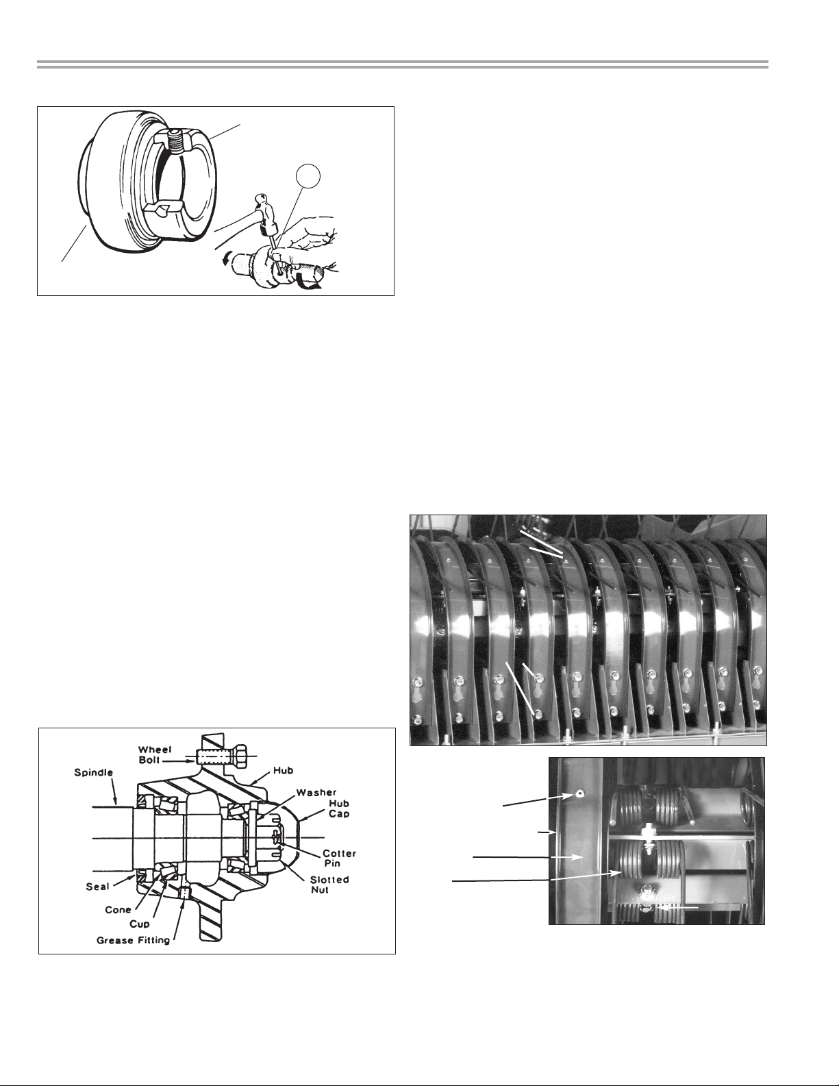
REPLACING OR REPACKING WHEEL BEARINGS
1. Remove wheel hubs and disassemble.
2. Clean bearings, seals, caps, washers, nuts and
hubs with kerosene or other solvent.
3. Replace bearings or seals if worn or damaged.
4. Pack bearing cones and seals with No. 2 multi-pur-
pose lithium grease or equivalent.
5. Reassemble hub and bearings. ( figure 2 )
a. Press cups against the shoulder in the hub.
b. Press seal flush into hub after bearing.
c. Place hub on shaft taking care not to damage
the seal!
d. Tighten the wheel bearing nut. Do not
overtighten.
e. Secure nut with a cotter pin.
f. Be sure to replace hub cap.
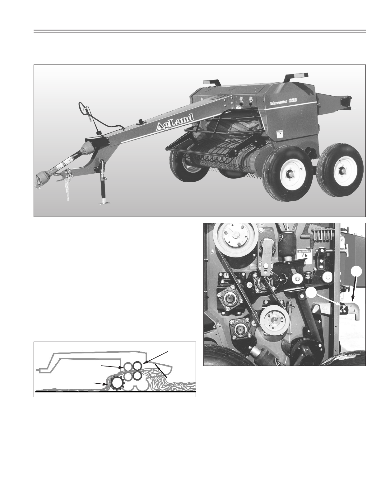
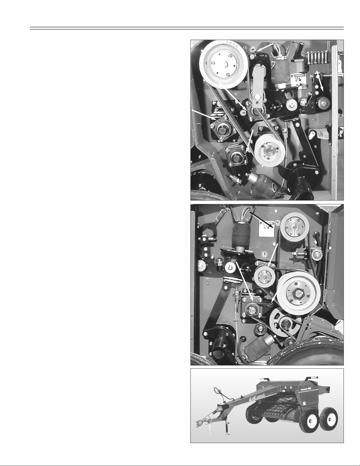
PICKUP TEETH, WRAPPERS, WEAR STRIPS
Check for bent, broken or loose parts. If it is necessary
to replace teeth or related parts, proceed as follows.
1. Ensure that your Macerator is blocked securely.
Loosen the bolts, holding the wrapper(s) on pickup. (fig.
3) Slide wrapper forward, and remove the wrapper from
the bolts.
“Pop”Rivets
Plastic Wear Strips
Wrapper
Teeth
2. Should the plastic wear strip require removal and
replacement, drill out or carefully grind off the “pop”
rivets. Replace strip with new rivets (figure 4).
3. Install new teeth or wrapper(s).
MAINTENANCE
Figure 4
Figure 3
16
two rivets
two bolts
1
locking collar
bearing
Figure 2
Figure 1

General information
We recommend a good grade SAE multi-pur-
pose high temperature grease.
Use a manual grease gun for all greasing. Air
powered grease guns may damage the seal
on the bearings.
Wipe all grease fittings with a clean cloth
before greasing to avoid injecting dirt or grit
in the bearings.
At the beginning of the season
Grease all the sealed bearings, front rollers (two
places), rear rollers ( two places) and drive shaft
one place, figures 1 and 2.
.
Note:
After lubricating, servicing, or adjusting the
Macerator, make sure all tools and equipment are
removed from Macerator to prevent damage.
LUBRICATION
17
Figure 1
Figure 2

AIR & HYDRAULIC SYSTEM
18
HYDRAULIC AND AIR SAFETY
AIR SYSTEM HYDRAULIC SYSTEM
HYDRAULIC SAFETY
Make sure that all components in the hydraulic
system are kept in good condition and are
clean.
Replace any worn, cut, abraded, flattened or
crimped hoses and metal lines.
Do not attempt any makeshift repairs to
hydraulic lines, fittings, or hoses by using tape,
clamps, or cements. The hydraulic system
operates under extremely high pressure:
1600to 2300 PSI (11 033 to 15 859 kPa). Such
repair will fail suddenly and create unsafe con-
ditions.
A high pressure concentrated stream of
hydraulic fluid can pierce the skin. If such hap-
pens, seek immediate medical attention as
infection and toxic reaction could develop.
Wear proper hand and face protection (eg. face
shield) when searching for a high pressure
hydraulic leak. Use a piece of wood or card-
board as a backdrop instead of hands.
Before applying pressure to the system, make
sure all connections are tight and that line,
hoses, and couplings are not damaged.
AIR SAFETY
Make sure all hoses and bellows are kept in
good condition and are clean.
Replace any damaged lines or bellows.
Do not exceed 110 lbs air pressure in tank and
90 lbs. in air bags.
Think SAFETY!
Work SAFELY!

PROBLEM POSSIBLE CAUSE SOLUTION
Pickup is skipping swath Missing or broken pickup teeth Replace missing teeth
or not picking cleanly Pickup to high Adjust pickup height
Driving to fast for pickup speed Use lower tractor gear with higher rpm
Not following the same direction as Follow the same direction as swath
swath was cut. was cut
Material wrapping in pickup Nylon wear plates missing or worn Replace missing or worn nylon pads
Pickup & travel speed not matched Match pickup & ground speed as
close as possible
Breakage or bending of Running pickup to low Adjust pickup height
pickup teeth Excessive pickup rotation speed in Reduce pickup or ground speed
rough or rocky conditions
Excessive noise or Insufficient oil in gear box Top up gear oil as needed
heat from gear box Worn or broken parts inside gear box Replace parts as needed
Air pressure does not hold Broken air line Repair or replace line as needed
in air tank and air bags Torn or punctured air bag Replace air bag as needed
Air regulator not working clean or replace air regulator
Pickup does not rise Worn or punctured hydraulic cylinder Replace hydraulic lines & cylinders
or lower or hydraulic oil line as needed
Bushings to tight Replace or clean bushings
Pickup height adjustment
does not hold Broken or worn parts on adjuster Replace worn parts as needed
Rubber rolls not feeding properly Air pressure to high or to low Adjust air pressure using the regulator
Gap between rollers to tight or to wide Adjust gap width
Wax build up on steel rolls Temperature & hay conditions cause The wax will come off after the rollers
the wax to come off the plant and cool down. A thin layer of wax/leaves
stick to the rollers will build up on the rollers
Excessive leaf loss Too much air pressure on steel rollers Release air pressure
Hay conditions to dry Condition hay early in the morning
The gap between steel rollers is to narrow Adjust gap between steel rollers
or the rolls going to fast
TROUBLE SHOOTING
19

TROUBLE SHOOTING
PROBLEM POSSIBLE CAUSE SOLUTION
Hay is not being macerated Not enough air pressure on steel rolls Adjust air pressure as required
Gap between rollers is to wide Narrow the gap between steel rollers
Windrow is to thick Cut wider or thinner windows
Steel rolls not running fast enough Increase tractor rpm
Swath not being Moldboard not adjusted Adjust moldboard angle.
inverted completely properly The tighter angle will result
in less inversion, The wider
angle will give you a greater
inversion.
20
Other manuals for Macerator 6600
1
Table of contents
Other AgLand Farm Equipment manuals
Popular Farm Equipment manuals by other brands

Chapman Machinery
Chapman Machinery BT500 Original instructions

Topcon
Topcon X35 Operator's manual

Trac Vac
Trac Vac DS400 instruction manual

BEFCO
BEFCO HURRICANE H80-076 Operator's manual

Titan Attachments
Titan Attachments ADJDISCP2 Operator's manual

Kongskilde
Kongskilde 800 Series Assembly Instructions & Operating Guide