Tru-Test WaterWell 2 User manual

1
US
ER GUIDE
WaterWell 2
WaterWell 4
Capacity Herd capacity Drinking height Weight
WaterWell 2 31 gal 110 beef 17.5 inches 97 lbs
119 L 110 beef 445 mm 44 kg
WaterWell 4 60 gal 200 beef 19.2 inches 129 lbs
226 L 200 beef 488 mm 58 kg
Capacidad Rebaño máx. Altura para beber Peso
WaterWell 2 31 galones 110 reses 17,5 pulgadas 97 libras
119 litros 110 reses 445 mm 44 kg
WaterWell 4 60 galones 200 reses 19,2 pulgadas 129 libras
226 litros 200 reses 488 mm 58 kg
English ..............................................................................................................................................................2
Español ...........................................................................................................................................................21

2
Contents
Safety warnings.........................................................................................................................................................................3
Warranty registration................................................................................................................................................................3
Before you start.........................................................................................................................................................................4
WaterWell 2 measurements..............................................................................................................................................4
WaterWell 4 measurements..............................................................................................................................................4
Basic concrete slab measurements....................................................................................................................................4
Concrete and tank hole alignment....................................................................................................................................5
Unpacking the box....................................................................................................................................................................6
Recommended parts .........................................................................................................................................................6
Recommended tools..........................................................................................................................................................6
Included parts ...................................................................................................................................................................7
Installation ................................................................................................................................................................................8
Cross-section of final installation ......................................................................................................................................8
Step 1: Preparing the site.................................................................................................................................................9
Step 2: Installing the water supply lines...........................................................................................................................9
Step 3: Installing the thermal earth tube .........................................................................................................................9
Step 4: Pouring the concrete slab ....................................................................................................................................9
Step 5: Preparing the vertical water supply line.............................................................................................................10
Step 6: Preparing the tank .............................................................................................................................................11
Step 7: Connecting the ¾ inch flex line and valve .........................................................................................................12
Step 8: Filling the tank...................................................................................................................................................13
Step 9: Setting the water level.......................................................................................................................................13
Pressure and flow capacity......................................................................................................................................................13
Recommendations...................................................................................................................................................................14
Split fence measurements ...............................................................................................................................................14
Training cattle to drink from the WaterWell....................................................................................................................15
Summer maintenance......................................................................................................................................................15
Winter maintenance........................................................................................................................................................15
General maintenance......................................................................................................................................................15
Troubleshooting ......................................................................................................................................................................16
Spare parts..............................................................................................................................................................................17
Valve and float................................................................................................................................................................18
Product warranty.....................................................................................................................................................................19
Notes ......................................................................................................................................................................................20

3
Safety warnings
Please read this guide carefully before you install the WaterWell 2 and/or the WaterWell 4.
Warning!
The installation of your WaterWell must be performed with rigorous adherence to national and local plumbing
and electrical codes. Failure to install or maintain your unit to the code standards may result in personal injury,
death or loss of livestock.
Warranty registration
Please supply us with your details so that we may register your product and keep you informed of any important updates.
See more at livestock.tru-test.com/en-us/livestock-waterer-warranty-registration-form
© 2017-2018 Tru-Test Limited.
All product names and brand names in this document are trademarks or registered trademarks of their respective holders.
No part of this publication may be photocopied, reproduced, stored in a retrieval system, or transmitted in any form or by any
means, electronic, mechanical, photocopying, recording or otherwise without the prior written permission of Tru-Test Limited.
Product specifications may change without prior notice.
For more information on other quality Tru-Test Group brands and products, visit www.tru-testgroup.com
Tru-Test Inc.
528 Grant Road
Mineral Wells
Texas 76067
UNITED STATES
Toll free: 800 874 8494
Fax: 940 327 8048
Although the information presented in this product document is believed to be accurate and reliable, no responsibility for
inaccuracies can be assumed by Tru-Test Limited. Tru-Test Limited reserves the right at any time to change characteristics or
specifications without notice.
All trademarks with an * are not owned by Tru-Test Limited and belong to their respective owners.
833399 Issue 4 1/2018

4
Before you start
Measure out the dimensions of the concrete slab needed, based on the WaterWell you have.
Length x Width x Overall Height Length x Width x Overall Height
WaterWell 2 43.3 x 27.6 x 20.2 inches 1101 x 701 x 513 mm
WaterWell 4 43.5 x 45.4 x 21.9 inches 1104 x 1154 x 555 mm
WaterWell 2 measurements
WaterWell 4 measurements
Basic concrete slab measurements

5
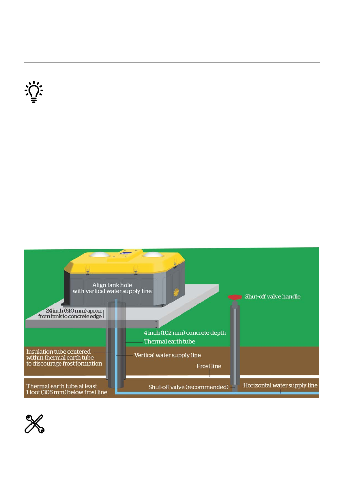
Concrete and tank hole alignment
Check your measurements to ensure that the opening on the bottom of the tank aligns with the thermal earth tube
placement in the concrete. The opening on the bottom of the tank is off center. Ensure that the water supply lines
are not touching the sides of the thermal earth tube.
Underneath the WaterWell 2
Underneath the WaterWell 4

6
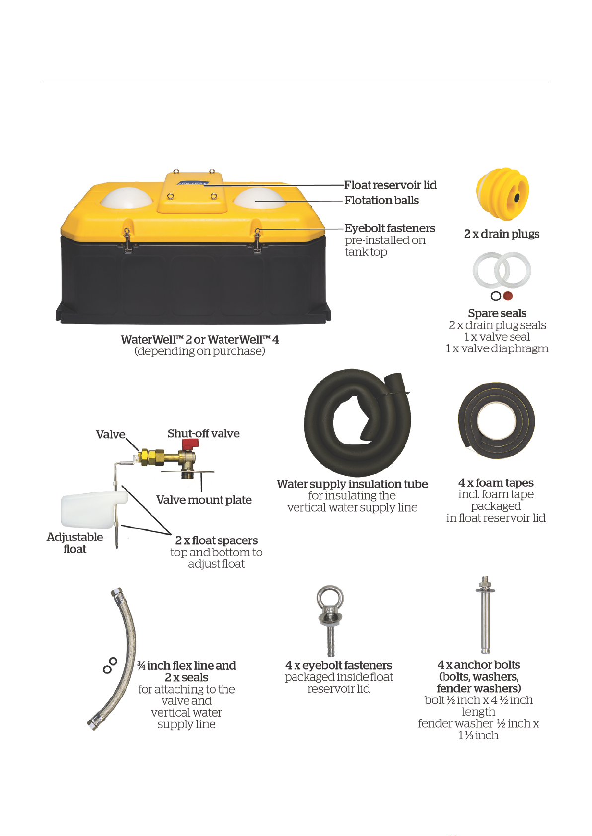
Unpacking the box
Recommended parts
•In colder climates, we strongly recommend the use of one or more thermal earth tubes to help keep the vertical water
supply line from freezing. The thermal earth tube(s) must be long enough to extend 1 foot (305 mm) below the normal
frost line.
•¾ inch NPT male fitting to connect the water supply line to the ¾ inch flex line inside the tank. If your water supply line is
more than ¾ inch in diameter, you will also need an adapter.
•Insulated thermal earth tube(s) suitable for your environment and frost line depth
Recommended tools
•Adjustable wrench
•Pipe wrench
•Measuring tape
•Utility knife
•Level
•⅜inch socket or ratchet wrench
•Hammer drill
•½ inch masonry bit
•Hammer
•½ inch ratchet wrench
•Caulk
7
Included parts
Get to know the parts of the WaterWell before you install it. Contact us on 800 874 8494 if anything is missing.
Images are indicative of shipped part and not shown to scale.
8
Installation
Cross-section of final installation
The WaterWell is designed to provide reliable fresh water to your livestock all year round.
When installing the WaterWell pay attention to the following areas:
•Choose a location where the tank will be sheltered from the elements.
•The vertical water supply line and the horizontal water supply line should all be installed to reach more than
1 foot (305 m) below the usual frost line.
•The concrete slab should have a 4 inch (102 mm) by 24 inch (610 mm) apron from the tank to the concrete
edge.
•Ensure that the placement of the water access hole in the concrete aligns with the anticipated placement of the
water access cavity of the waterer.
•WaterWell 2: Make sure that your vertical water supply line with ¾ inch male NPT fitting attached is
¾ - 1 inch (19 - 25 mm) below the top of concrete.
•WaterWell 4: Make sure that your vertical water supply line with ¾ inch male NPT fitting attached is
2 inches (51 mm) above the top of concrete.
•The water supply line should be centered in the thermal earth tube (if using) to help discourage frost formation.
•To be effective, the thermal earth tube(s)* must be installed to reach at least 1 foot (305 mm) below the usual
frost line.
*Note that more than one thermal earth tube may be required.
•It is recommended to caulk the base of the tank to prevent moisture and wind penetration.
In addition to the shut-off valve located inside the unit, we strongly recommend that a second, external shut-off
valve be installed outside of the concrete.
9
Have you turned off the water?
Step 1: Preparing the site
aChoose a location that is easily accessible by livestock and sheltered from the elements.
bCheck the measurements of your WaterWell against the size of the concrete slab you need to pour. See
Concrete and tank
hole alignment
on page 5.
cThe circular opening (hole) underneath the tank is off center. Note where the thermal earth tube will align with the hole
under the tank. See
Concrete and tank hole alignment
on page 5.
Check that you have aligned the hole in the concrete with the access cavity under the WaterWell.
Step 2: Installing the water supply lines
aThe horizontal water supply line should be at least 1 foot (305 mm) below the frost line.
bStrongly recommended: If installing a shut-off valve, install it on the horizontal water supply line leading up to the tank
(located outside the perimeter of the concrete slab).
cThe vertical water supply line should be ¾ inches in diameter to connect to the horizontal water supply line. If your vertical
water supply line is not ¾ inches in diameter, you will need an adaptor.
dRun the vertical water supply line about 10 inches (250 mm) above ground. You will cut it to a more precise length later.
Step 3: Installing the thermal earth tube
aInstall a thermal earth tube around the vertical water supply line. It must be at least 1 foot (305 mm) below the frost line.
Ensure that the vertical water supply line is centered within the thermal earth tube.
bIf you are in a colder climate, we recommend an additional thermal earth tube be used to reach below the frost line by at
least another foot (305 mm).
Step 4: Pouring the concrete slab
aBefore you pour the concrete, check that you are using the correct measurements for your WaterWell. See
Concrete and
tank hole alignment
on page 5.
bInstall the thermal earth tube so that it is flush with the top of the concrete.
Do not pour concrete into the thermal earth tube or fill the space with di
rt or any other material, as it will prevent
warm air below the frost line from circulating around the vertical water supply line, and will cause the water line to
freeze.

10
Step 5: Preparing the vertical water supply line
For the WaterWell 2:
Cut the vertical water supply line, and make sure it sits ¾ - 1 inch (19 - 25 mm) below the top of the concrete with the
¾ inch NPT fitting attached. This allows ample space to connect the ¾ inch flex line to the valve, and then push any excess
flex line back down through the access cavity.
If the vertical water supply line is not cut to the required length, it will be difficult to connect to the valve and push
any excess ¾ inch flex line back down through the access cavity.
For the WaterWell 4:
Cut the vertical water supply line, and make sure it sits 2 inches above the top of the concrete with the ¾ inch NPT fitting
attached. This allows ample space to connect the ¾ inch flex line to the valve, and then push any excess flex line back down
through the access cavity.
If the vertical water supply line is not cut to the required length, it will be difficult to connect to the valve and push
any excess ¾ inch flex line back down through the access cavity.
aCut the supply line per the details pictured above, and attach a ¾ inch NPT male fitting onto the end of the vertical water
supply line. This will connect to the WaterWell ¾ inch flex line.
bInsert one seal (supplied with the ¾ inch flex line) into one end of the flex line. Connect that end to the vertical supply line
and tighten with a pipe wrench.
cTurn on the water to flush the line to remove dirt and debris, and to check for leaks at the connection. Turn off the water.

11
dSlide the water supply insulation tube over the ¾ inch flex line and vertical water supply line, making sure that the
insulation tube reaches up to the valve.
0
Step 6: Preparing the tank
aTurn the tank on its side.
bApply the foam tape 1 to position 1 on the bottom of the tank, around the outside edge (recessed channel), of the hole on
the bottom of the tank (where the thermal earth tube will align).
cApply the foam tape 2 to position 2 on the bottom of the tank, around the outside edge (recessed channel).
dFoam tape 3 is pre-installed under the tank top lid, and no further installation is required.
eFinally, apply the foam tape that shipped with the reservoir lid.
fUnscrew the WaterWell valve or disconnect it from the tank. Remove the valve mounting plate assembly by unscrewing
the three hex bolts.
gLift the tank and carefully place it over the vertical water supply line and ¾ inch flex line, so that the ¾ inch flex line comes
up through the tank top opening. The end of the ¾ inch flex line should be 2-3 inches above the opening. This allows
room to make connections to the valve. Excess line will be pushed back down into the tank bottom later.

12
Step 7: Connecting the ¾ inch flex line and valve
aInstall the remaining seal into the top of the ¾ inch flex line.
bConnect the ¾ inch flex line to the valve and plate assembly. Do not over tighten.
cTurn on the water and check for leaks. Turn off the water.
dCarefully push excess ¾ inch flex line back down through the tank bottom or opening of the tank.
eReattach the valve mount plate assembly to the tank with the supplied hardware and tighten.
Ensure that the O-ring is properly placed around the diameter of the tank opening before tightening the valve
mount plate assembly.
fOpen the shut-off valve.
If high water pressure is an issue, the shut-
off valve can be used to help reduce the flow of water into the valve.
We recommend the use of a pressure reducer in situations where water pressure exceeds 87 psi. (See
Pres
sure and
flow capacity
on page 15 if using a pressure valve).

13
Step 8: Filling the tank
aCheck that both drain plugs are screwed in tightly.
bTurn on the water supply to fill the tank and check for leaks. If no leaks are found, put the flotation balls in the tank,
attach the tank top and float reservoir lid and fasten with supplied hardware.
cDrill ½ inch holes in the concrete using the moulded mounting openings found on each corner of the WaterWell.
dInsert anchor bolts in each hole. Place washers over anchor bolts, then apply the nut. Tighten the nut and repeat on all
four corners so that the WaterWell is securely mounted.
eWe recommend caulking the perimeter of the tank to protect it from wind and debris.
Step 9: Setting the water level
Remove the float reservoir lid. Adjust the water to the desired level using the top and bottom spacers on the float. Once the
water level is set, attach the float reservoir lid and tighten hardware.
When training cattle, adjust float to the lowest setting.
In the winter, check that the flotation balls are not floating up tightly against the drink holes as this m
ay cause
them to freeze shut in the openings. Adjust the water level so that there is a credit card's width of space
between the balls and the drink opening.
Pressure and flow capacity
You may need to install a pressure reducer on the vertical water supply line in hilly areas where the water pressure is affected.
WaterWell 2 and WaterWell 4
PSI Flow (Gal/min) Flow (L/min)
14.5 3.72 14.1
29 5.5 20.9
43.5 8.19 31
58 10 37.9
72.5 11.6 43.9
87 MAX 12.7 48

14
Recommendations
Split fence measurements
The WaterWell can also be used to split two pastures or pens with a fence line separating the drinking holes. This allows
animals from both sides of the fence to have access to water.
Check that you have enough clearance between the float reservoir lid and fence so that you can lift the lid to get to
the valve and float assembly.

15
Training cattle to drink from the WaterWell
Adjust the water level to the lowest setting.
Remove the flotation balls and allow the animals to drink freely from the tank. After a few days, adjust the water level to the
desired height and introduce one or all of the flotation balls back into the unit.
Summer maintenance
Adjust the water level so the flotation balls sit tightly up against the drink openings. This helps to keep pests out of the water
and will also discourage algae growth.
Winter maintenance
Adjust the float so the water level is lower to prevent flotation balls from freezing to the drink openings. (You should be able
to fit a credit card between the flotation balls and drink openings).
(Optional) Replace the white flotation balls with black ones to encourage the absorption of heat from the sun.
General maintenance
If you are not using your WaterWell for extended periods of time, drain the tank and shut off the main water supply to the
tank.
Clean the tank regularly to remove debris.
Depending upon the quality of the water supply, we recommend checking all seals and the diaphragm on an annual basis.

16
Troubleshooting
Symptom Possible cause/s Solution/s to check or action:
Water frozen in tank Water frozen in lines or
connections.
Vertical water supply line is properly insulated.
Tank bottom is sealed on concrete.
Cattle are drinking from the WaterWell, if not, drain and refill to
recycle fresh water.
Vertical water supply line is centered in the thermal earth tube.
Horizontal water supply line is 1 foot (51 mm) below the frost
line.
Low water flow Blockage or kinks in valves or
vertical water supply line.
Shut-off valve not set correctly.
Vertical water supply line is free from kinks.
Valve and float assembly has no blockages.
Shut-off valve is set to the open position. See images of shut-off
valve positions on page 12 .
Check water pressure with a pressure gauge.
Water dripping out of
valve
Seals may need replacing. Top and bottom spacers are set allowing the float to move.
Valve and float assembly is clear of debris. Check the valve
diaphragm and seals.
Check that the valve connections have been tightened.
The shut-off valve is set to the open position. See images of shut-
off valve positions on page 12.
Flotation balls stuck
to tank top
Flotation balls frozen in drink
openings.
Use hot water to thaw the flotation balls and then adjust the
water so there is a space between the balls and the drink
openings.
Apply petroleum jelly to the drink openings.
Valve does not shut-
off
Worn diaphragm. Replace valve and float assembly diaphragm.
Check pressure and flow capacity. See
Pressure and flow capacity
on page 15.
Drain plugs leak Worn O-ring or loose plug. Replace drain plug O-ring.
Tighten drain plug.
17
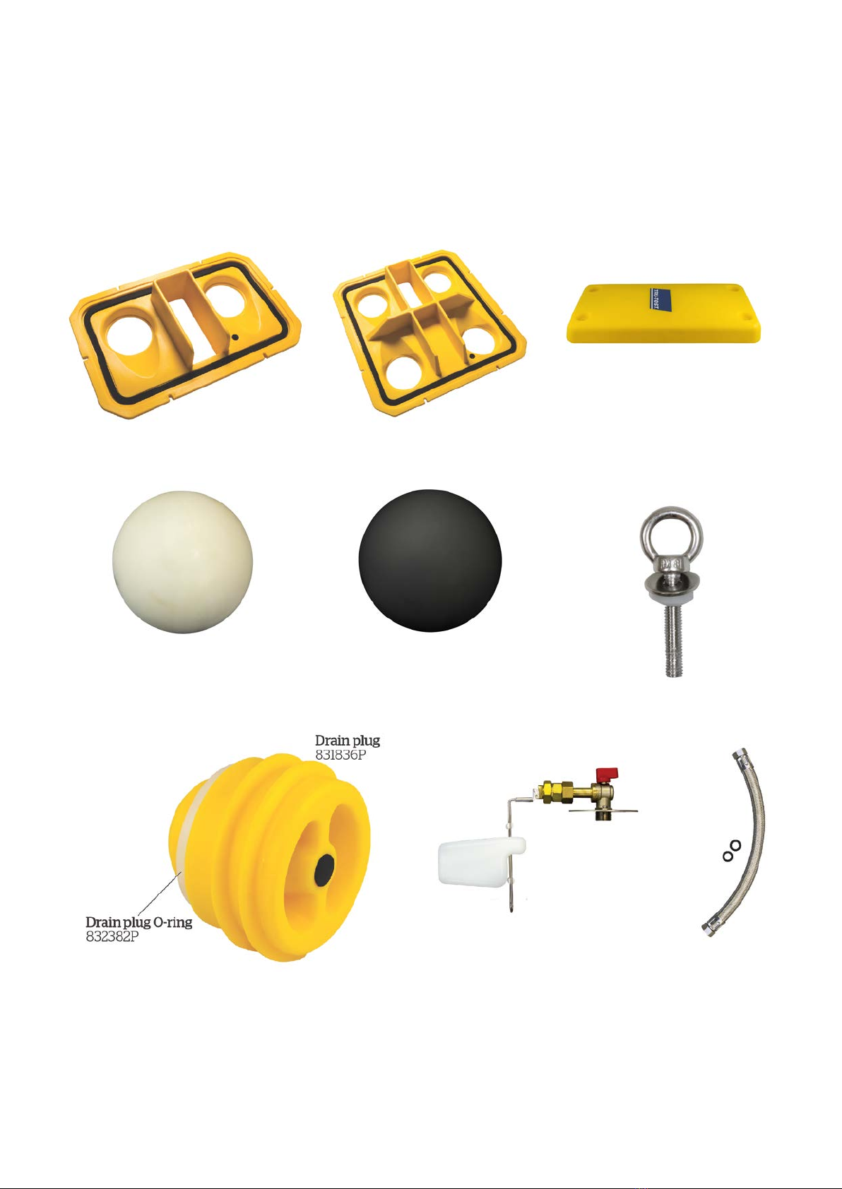
Spareparts
The parts below are available to order from your local Tru-Test WaterWell supplier.
Images are indicative of spare part and not shown to scale.
Tank top WaterWell 2 Tank top WaterWell 4 Float reservoir lid
832889P
832890P
832891P
Flotation balls WHITE Flotation balls BLACK Float reservoir fastener kit
832877P
832878P
832893P
Eyebolt fastener, nut and washer (3 pc)
Drain plug and drain plug O-ring Valve and float
See overleaf for details of spare parts
18
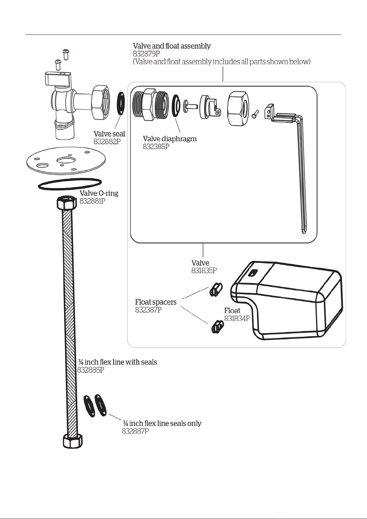
Valve and float

19
Product warranty
Terms and Conditions for Livestock Automatic Watering Products
Effective July 2017
Tru-Test, Inc.’s warranty obligations for Livestock Automatic Watering products manufactured by or for
Tru-Test, Inc. are limited to the terms set out in this policy.
Tru-Test, Inc. warrants its products to be free of defective materials and workmanship for the periods outlined below.
If a warranted defect occurs, please return the product along with proof of purchase to the place of purchase. If Tru-Test Inc.
receives a valid claim within the Warranty Period, Tru-Test Inc. will, at its option:
•Repair the product at no charge, using new replacement parts.
•Exchange the product with a product that is new or has functionality equivalent to the original product; or
•Refund the product’s original purchase price.
Warranty Period
The period of warranty (warranty period) begins at original date of purchase and runs for the following terms:
Base, Top and Float Reservoir Lid
•Eight years against manufacturing defect.
Component Parts (floats, valves, drain plugs, fasteners)
•One year against manufacturing defect.
Exclusions and Limitations
This warranty applies only to genuine Tru-Test products manufactured by or for Tru-Test, Inc.
The liability of Tru-Test, Inc. under this warranty is excluded to the extent that any defect has been caused or contributed to by:
•Any accident, contamination, tampering, modification, willful damage, improper storage, improper use or negligent act of,
or by omission by, any person other than Tru-Test, Inc.;
•Improper installation of the unit, or deterioration of the base upon which it rests;
•The use of the unit for any other purpose than providing a stationary source of water for livestock;
•The use of the unit for any other purpose than for which it was intended;
•The use of anything other than the original equipment or manufacturer’s parts;
•Any damage to the unit caused by storm, landslide, fire, lightning, earthquake, tornado or any other naturally occurring
phenomenon;
•Any damage to the unit caused by vermin or other pest, and any undermining of the base upon which the unit sits through
any cause whatsoever;
•This warranty specifically excludes the unit color, which may fade or change over time.
To the maximum extent permitted by law, this warranty is exclusive, personal to you, non-transferable, and in lieu of all other
warranties, representations or conditions relating to this product (whether express or implied and whenever arising) whether
originating by statute, law, trade, custom or otherwise.
The product warranty is only valid in the original country of purchase. Any claims made in another country may incur full repair
costs at the owner’s expense.

20
Notes
This manual suits for next models
1
Table of contents
Languages:
Other Tru-Test Farm Equipment manuals


