manuals.online logo
Brands
  1. Home
  2. •
  3. Brands
  4. •
  5. Allied Telesis
  6. •
  7. Media Converter
  8. •
  9. Allied Telesis Converteon AT-CV102 Series User manual

Allied Telesis Converteon AT-CV102 Series User manual

1 2 3
613-000296 Rev. D
AT-CV10x Series Converteon Line Cards
Installation Guide
Overview
The AT-CV10x Series (AT-CV101, AT-CV102, and AT-CV102/x Series) line cards feature
a 10Base-TX twisted pair port and a 100Base-FX fiber optic port. You can install these
line cards in any Converteon Series chassis. The line card features one fiber optic port
and one copper twisted pair port. Both ports feature half- or full-duplex mode operation.
The line cards are hot-swappable into and out of a Converteon chassis.
Related Documents
For details on the features and functions of a Converteon chassis, refer to the relevant
documents on our web site, www.alliedtelesis.com.
Verifying Package Contents
Ensure that the following items are included in your package:
One AT-CV10x Series line card
This installation guide
If any item is missing or damaged, contact your Allied Telesis sales representative for
assistance.
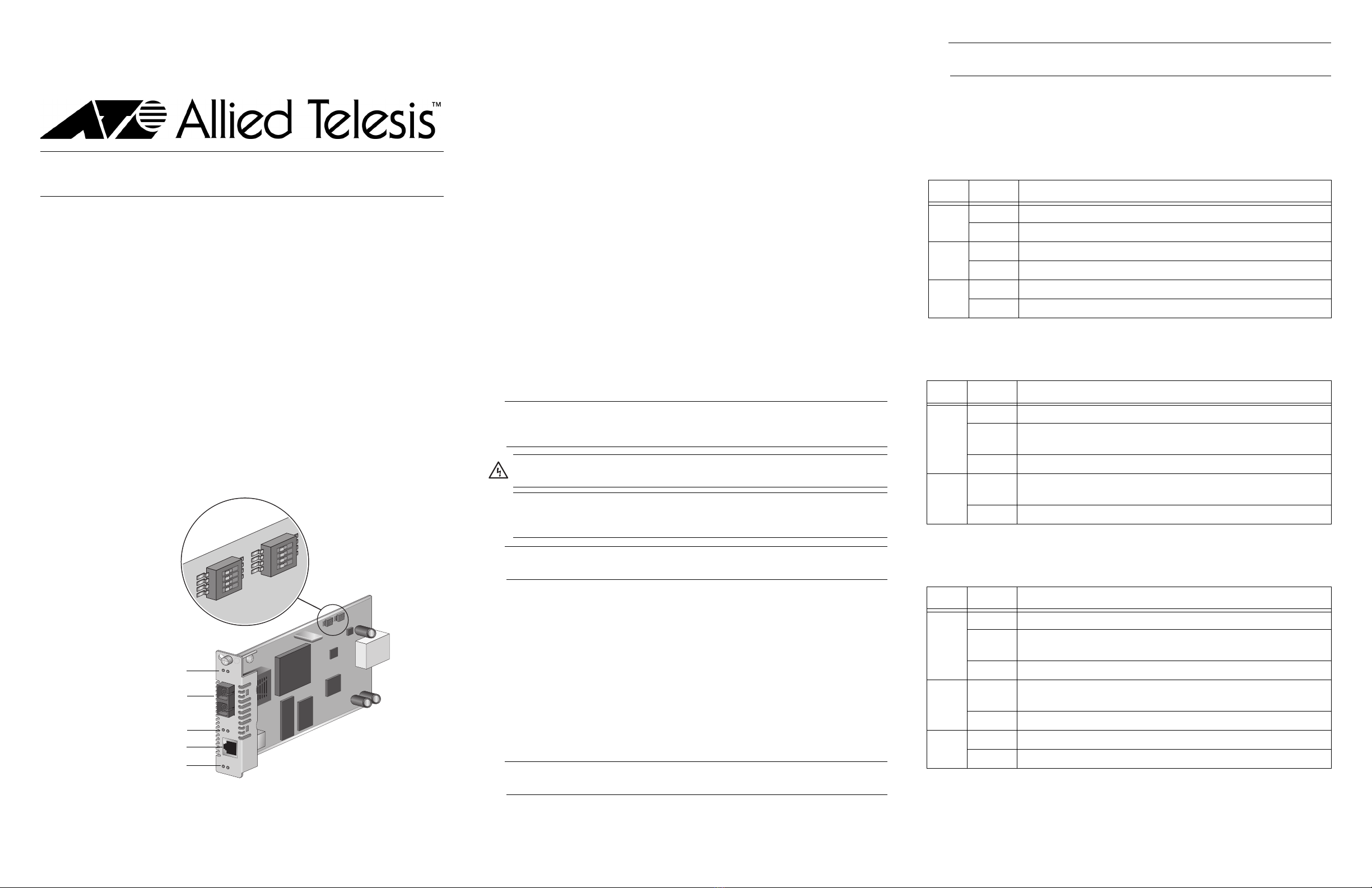
AT-CV10x Series Line Card Components
An AT-CV10x Series line card has the components shown below. The AT-CV102 line card
is shown as an example.
Port Descriptions
Fiber Optic Port
The fiber optic port on the AT-CV10x Series line card is IEEE 802.3ah-compliant. The
connectors and operating distance vary depending upon the model:
AT-CV101: multi-mode fiber ST connector and a maximum operating distance of 2km
(1.24 miles)
AT-CV102: multi-mode fiber SC connector and a maximum operating distance of 2km
(1.24 miles)
AT-CV102/1: single mode fiber SC connector with a maximum operating distance of
15km (9.32 miles)
AT-CV102/2: single mode fiber SC connector with a maximum operating distance of
40km (24.85 miles)
Twisted Pair Port
The 10/100Base-TX compliant twisted pair port has an RJ-45 connector and a maximum
operating distance of 100 meters (328 feet). Category 5 (5E), 100 Ohm shielded or
unshielded twisted pair cabling is required. The pinouts for this port are shown in
“Twisted Pair Port Pinouts.”
LEDs
An AT-CV10x Series line card as three status LEDs, two LEDS for the fiber optic port, and
three LEDs for the twisted pair port, as described in “LED Descriptions.”
DIP Switches
Two sets of DIP switches allow you to set the operating mode and MDI/MDI-X features, as
described in “DIP Switch Settings.”
Installing an AT-CV10x Series Line Card
Note
Before you install an AT-CV10x Series line card, refer to the appropriate Converteon
chassis installation guide for electrical safety and emissions information.
Note
You can install a Converteon line card in any Converteon chassis line card slot.
To install an AT-CV10x Series line card, perform the following procedure:
1. Remove the AT-CV10x Series line card from its shipping package and store the
package in a safe place. You must use the original package if you need to return the
unit to Allied Telesis.
2. Configure the line card’s DIP switches as required. Refer to “DIP Switch Settings” for
more information.
3. Select any line card slot in the chassis where you want to install the AT-CV10x
Series line card, and remove the blank slot cover if one is installed.
4. Align the back edge of the line card with the to and bottom alignment guides located
inside the slot.
5. Slide the line card into the slot until the front of the card is flush with the front of the
chassis.
Note
Avoid touching the line card components.
6. Secure the AT-CV10x Series line card to the chassis by using a Phillips screwdriver
to tighten the captive screw on the faceplate.
Note
Always tighten the captive screw to secure the line card to the chassis.
7. Repeat this procedure to install additional AT-CV10x Series line cards.
LED Descriptions
Status LEDs
The line card has three status LEDs as described in the following table. For more
information about Smart MissingLink and MissingLink, refer to the relevant management
software user’s guide.
Fiber Optic Port LEDs
The fiber optic port has two LEDs, as described in the following table. For more
information about Smart MissingLink, refer to the relevant management software user’s
guide.
Twisted Pair Port LEDs
The twisted pair port has three LEDs, as described in the following table. For more
information about Smart MissingLink, refer to the relevant management software user’s
guide.
*613-000296 Rev D*
555
3K
1 2 3 4
3K
1 2 3 4
SW1
SW2
AT-CV10 2
LK AT
T
X
SMLML
RDY
LK AT
T
X
M
M
R
X
3K
1 2 3 4
3K
1 2 3 4
SW1
SW2
ON ON
SW1 DIP Switch Set
SW2 DIP Switch Set
Fiber Optic Port LEDs
Fiber Optic Port
Twisted Pair Port LEDs
Line Card Status LEDs
10/100-TX Twisted Pair Port
Warning: Remove all metal jewelry, such as rings and watches, before installing
or removing a line card from a powered-on chassis.
Caution: Be sure to observe all standard electrostatic (ESD) precautions, such as
wearing an antistatic wrist strap, to avoid damaging the device. A line card can be
damaged by static electricity
LED State Description
RDY Green The line card has passed diagnostics.
Off The line card has not passed diagnostics.
SML Green The Smart MissingLink mode is enabled.
Off The Smart MissingLink mode is disabled.
ML Green The MissingLink mode is enabled.
Off The MissingLink mode is disabled.
LED State Description
LK Green A link has been established on the port.
Blinking
Green
While in Smart MissingLink mode, a valid connection is established
on the port while a link on the other port is lost.
Off No link has been established on the port.
AT Blinking
Green
TX/RX activity has been detected on the port.
Off There is no TX/RX activity on the port.
FD Green (AT-CV102 only) The port is operating in full-duplex mode.
Off The port is operating in half-duplex mode.
456
DIP Switch Settings
SW 1 DIP Switches
The DIP switches in the SW 1 DIP switch set described in the following table allow you to
set the operating mode of the line card. For information about the operating modes as
well as Smart MissingLink and MissingLink, refer to the relevant management software
user’s guide.
“X” means that the DIP switch position can be ON or OFF.
SW 2 DIP Switches
The DIP switches in the SW 2 DIP switch set described in the following table allow you to
configure the MDI/MDI-X feature on the twisted pair port..
“X” means that the DIP switch position can be ON or OFF.
Twisted Pair Port Pinouts
The pinouts for the RJ-45 twisted pair port are shown in the following illustration.
The following table lists the RJ-45 pin signals when a twisted pair port is operating in the
MDI or MDI-X mode.
Warranty Information
The AT-CV10x Series (AT-CV101, AT-CV102, and AT-CV102/x Series) line cards have a
limited warranty of five years. Go to www.alliedtelesis.com/warranty for the specific terms
and conditions of the warranty and for warranty registration.
Specifications
Physical, Environmental, and Electrical Ratings
Dimensions (H x W x L) (2.2 cm x 7.3 cm x 13.0 cm)
.855 in. x 2.89 in. x 5.1 in.
Weight 0.27kg (0.60 lbs.)
Operating Temperature 0° C to 40° C (32° F to 104° F)
Storage Temperature -25° C to 70° C (-13° F to 158° F)
Operating Relative Humidity 5% to 90% (non-condensing)
Storage Relative Humidity 5% to 95% (non-condensing)
Operating Altitude Range Up to 3,048 m (10,000 ft.)
Predicted MTBF (Telcordia SR332) AT-CV101 1,020,000 hours
AT-CV102 890,000 hours
AT-CV102/1 1,020,000 hours
AT-CV102 1,020,000 hours
Power Consumption 5.7 Watts
Optical Output Power (dBm)
Receiver Power Sensitivity (dBm)
Electrical Safety and Emissions Statements
This product meets the following standards when installed in compliant host equipment.
Emissions FCC Class A, EN55022 Class A, VCCI Class A, C-TICK, CE
Warning: In a domestic environment this product may cause radio interference in which
case the user may be required to take adequate measures.
Immunity EN55024
Electrical Safety UL60950 (cULus), EN60950 (TUV), CSA22.2 No. 950
Copyright © 2007 Allied Telesis, Inc. All rights reserved.
No part of this publication may be reproduced without prior written permission from Allied
Telesis, Inc.
Operating Mode DIP 1 DIP 2 DIP 3 DIP 4
Link Test (default) OFF OFF OFF X
Smart MissingLink (SML) OFF ON ON X
MissingLink (ML) OFF OFF ON X
Manufacturing Default Settings OFF OFF OFF OFF
Operating Mode DIP 1 DIP 2 DIP 3 DIP 4
Auto MDI-X Enabled (default) X OFF X X
Auto MDI-X Disabled X ON X X
Manufacturing Default Settings OFF OFF OFF OFF
MDI Mode MDI-X Mode
Pin Signal Pin Signal
1 TX+ 1 RX+
2 TX- 2 RX-
3 RX+ 3 TX+
6 RX- 6 TX-
8
8
11
Line Card Minimum Maximum Wavelength Connector
AT-CV101 -20 dBm -14 dBm 1310 nm Dual ST
AT-CV102 -20 dBm -14 dBm 1310 nm Dual SC
AT-CV102/1 -15 dBm -5 dBm 1310 nm Dual SC
AT-CV102/2 -15 dBm 0 dBm 1310 nm Dual SC
Line Card Minimum Maximum
AT-CV101 -31 dBm -11 dBm
AT-CV102 -31 dBm -11 dBm
AT-CV102/1 -34 dBm -3 dBm
AT-CV102/2 -34 dBm -3 dBm
U.S. Federal Communications Commission
Radiated Energy
Note: This equipment has been tested and found to comply with the limits for a Class A digital device pursuant to
Part 15 of FCC Rules. These limits are designed to provide reasonable protection against harmful interference
when the equipment is operated in a commercial environment. This equipment generates, uses, and can radiate
radio frequency energy and, if not installed and used in accordance with this instruction manual, may cause
harmful interference to radio communications. Operation of this equipment in a residential area is likely to cause
harmful interference in which case the user will be required to correct the interference at his own expense.
Note: Modifications or changes not expressly approved of by the manufacturer or the FCC, can void your right to
operate this equipment.
Industry Canada
This Class A digital apparatus meets all requirements of the Canadian Interference-Causing Equipment
Regulations.
Cet appareil numérique de la classe A respecte toutes les exigences du Règlement sur le matériel brouilleur du
Canada.

This manual suits for next models

5

Other Allied Telesis Media Converter manuals

Allied Telesis MMC10G Series User manual

Allied Telesis

Allied Telesis MMC10G Series User manual

Allied Telesis AT-MC13 User manual

Allied Telesis

Allied Telesis AT-MC13 User manual

Allied Telesis Converteon AT-CV5M01 User manual

Allied Telesis

Allied Telesis Converteon AT-CV5M01 User manual

Allied Telesis AT-MCF106ST User manual

Allied Telesis

Allied Telesis AT-MCF106ST User manual

Allied Telesis AT-IMC1000T/SFP User manual

Allied Telesis

Allied Telesis AT-IMC1000T/SFP User manual

Allied Telesis AT-MC1005/2 User manual

Allied Telesis

Allied Telesis AT-MC1005/2 User manual

Allied Telesis Converteon AT-CV1KSS User manual

Allied Telesis

Allied Telesis Converteon AT-CV1KSS User manual

Allied Telesis CONVERTEON AT-CM201 User manual

Allied Telesis

Allied Telesis CONVERTEON AT-CM201 User manual

Allied Telesis AT-MC1004 User manual

Allied Telesis

Allied Telesis AT-MC1004 User manual

Allied Telesis AT-MC104XL User manual

Allied Telesis

Allied Telesis AT-MC104XL User manual

Allied Telesis Converteon AT-CV1KSS User manual

Allied Telesis

Allied Telesis Converteon AT-CV1KSS User manual

Allied Telesis AT-MC605 User manual

Allied Telesis

Allied Telesis AT-MC605 User manual

Allied Telesis AT-MC13 User manual

Allied Telesis

Allied Telesis AT-MC13 User manual

Allied Telesis Converteon AT-CV5000 User manual

Allied Telesis

Allied Telesis Converteon AT-CV5000 User manual

Allied Telesis AT-G8BD-13 User manual

Allied Telesis

Allied Telesis AT-G8BD-13 User manual

Allied Telesis AT-MC102XL User manual

Allied Telesis

Allied Telesis AT-MC102XL User manual

Allied Telesis AT-G8LX10 User manual

Allied Telesis

Allied Telesis AT-G8LX10 User manual

Allied Telesis AT-MC13 User manual

Allied Telesis

Allied Telesis AT-MC13 User manual

Allied Telesis AT-PB10 Series User manual

Allied Telesis

Allied Telesis AT-PB10 Series User manual

Allied Telesis AT-GS2002/SP User manual

Allied Telesis

Allied Telesis AT-GS2002/SP User manual

Allied Telesis AT-MC101XL User manual

Allied Telesis

Allied Telesis AT-MC101XL User manual

Allied Telesis DMC1000/100 Series User manual

Allied Telesis

Allied Telesis DMC1000/100 Series User manual

Allied Telesis AT-MC101XL User manual

Allied Telesis

Allied Telesis AT-MC101XL User manual

Allied Telesis AT-MC1008/GB User manual

Allied Telesis

Allied Telesis AT-MC1008/GB User manual

Popular Media Converter manuals by other brands

American Dynamics RCSN422 Specifications

American Dynamics

American Dynamics RCSN422 Specifications

ICP DAS USA I-2532 user manual

ICP DAS USA

ICP DAS USA I-2532 user manual

CYP PRO-SDI2H Operation manual

CYP

CYP PRO-SDI2H Operation manual

KROHNE UFC 400 Supplementary instructions

KROHNE

KROHNE UFC 400 Supplementary instructions

Danfoss VLT AutomationDrive FC 300 quick start guide

Danfoss

Danfoss VLT AutomationDrive FC 300 quick start guide

Wavtech Link8 owner's manual

Wavtech

Wavtech Link8 owner's manual

Lika Rotapuls C58 quick start guide

Lika

Lika Rotapuls C58 quick start guide

Panasonic AJUFC1800P - FORMAT CONVERTER operating instructions

Panasonic

Panasonic AJUFC1800P - FORMAT CONVERTER operating instructions

Philips Streamium WAS5 Specifications

Philips

Philips Streamium WAS5 Specifications

argon audio Stream3M manual

argon audio

argon audio Stream3M manual

Absolute Process Instruments DuoPak APD 2050 manual

Absolute Process Instruments

Absolute Process Instruments DuoPak APD 2050 manual

Sondigo sirocco user manual

Sondigo

Sondigo sirocco user manual

Thor Broadcast H-IP-HDMI user manual

Thor Broadcast

Thor Broadcast H-IP-HDMI user manual

DRAKE DSE24A instruction manual

DRAKE

DRAKE DSE24A instruction manual

Ensemble Designs Avenue 7910 manual

Ensemble Designs

Ensemble Designs Avenue 7910 manual

CYP CV-400H Operation manual

CYP

CYP CV-400H Operation manual

Omnitron Systems Technology miConverter 10/100 Specifications

Omnitron Systems Technology

Omnitron Systems Technology miConverter 10/100 Specifications

Clarion DRB3375V Service manual

Clarion

Clarion DRB3375V Service manual

manuals.online logo
manuals.online logoBrands
  • About & Mission
  • Contact us
  • Privacy Policy
  • Terms and Conditions

Copyright 2025 Manuals.Online. All Rights Reserved.