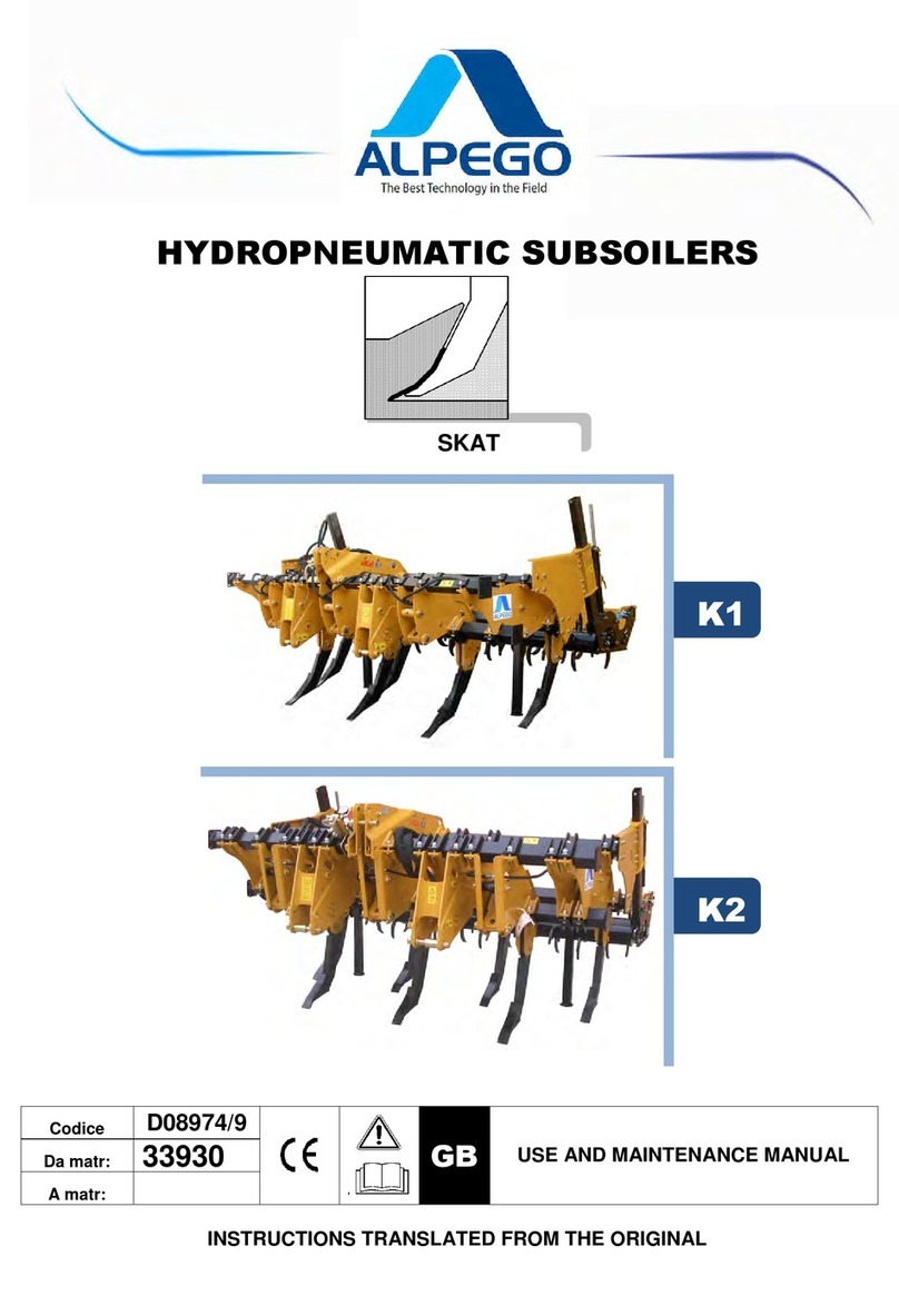
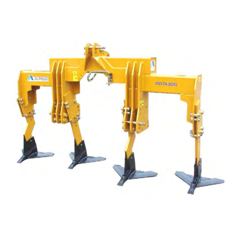
Alpego K-DYNO User manual

Code : Q00A00203 Use and
maintenance manual
Translation of the
original instructions
Read these instructions carefully before first use.
MECHANICAL SUBSOILERS MODELS:
K-DYNO
K-EVO
K-FORCE
Subsollers

Strictly confidential information - All rights to the contents of this document are reserved. It is forbidden to copy, use, distribute, even partially or
otherwise circulate such information, unless expressly authorised by "ALPEGO S.p.a.". Violations will be prosecuted in accordance with the law.
2Code : Q00A00203 - Rev. 00_07/2021

Strictly confidential information - All rights to the contents of this document are reserved. It is forbidden to copy, use, distribute, even partially or
otherwise circulate such information, unless expressly authorised by "ALPEGO S.p.a.". Violations will be prosecuted in accordance with the law.
3
Code : Q00A00203 - Rev. 00_07/2021
Summary
SUMMARY ............................................................................................................................................................ 3
LIST OF FIGURES ............................................................................................................................................... 6
LIST OF TABLES ................................................................................................................................................. 7
1 GENERAL INFORMATION..................................................................................................................... 8
1.1 Generalities................................................................................................................................................ 8
1.1.1 Copyrights.................................................................................................................................................. 8
1.1.2 Use and storage of the manual.................................................................................................................. 8
1.1.3 Symbols used in this manual.....................................................................................................................9
1.1.4 Terminology and definitions ..................................................................................................................... 10
1.1.5 Numbering of figures and tables..............................................................................................................10
1.2 Description of personnel..........................................................................................................................10
1.2.1 USER.......................................................................................................................................................10
1.2.2 MECHANICAL REPAIRER ...................................................................................................................... 11
1.3 Guarantees.............................................................................................................................................. 11
1.4 Updating the manual................................................................................................................................ 12
1.5 Cooperation with the user........................................................................................................................12
2 MANUFACTURER AND MACHINE DATA .......................................................................................... 13
2.1 Manufacturer and machine identification data.........................................................................................13
2.1.1 Manufacturer's name and address ..........................................................................................................13
2.1.2 Instructions for requesting interventions..................................................................................................13
2.1.3 EC Declaration of Conformity .................................................................................................................. 14
2.1.4 Machine identification ..............................................................................................................................15
2.2 Machine description.................................................................................................................................16
2.2.1 Intended use............................................................................................................................................16
2.2.2 Reasonably foreseeable misuse.............................................................................................................. 16
2.3 Technical characteristics of the machine ................................................................................................. 17
2.3.1 Technical specifications KDyno ............................................................................................................... 17
2.3.2 KEvo technical specifications ..................................................................................................................17
2.3.3 KForce technical specifications ...............................................................................................................18
2.3.4 Noise........................................................................................................................................................ 18
2.4 Machine parts ..........................................................................................................................................19
2.4.1 KDyno......................................................................................................................................................19
2.4.2 KEvo ........................................................................................................................................................20
2.4.3 KForce .....................................................................................................................................................21
3 LEGAL REFERENCES AND RESPONSIBILITIES............................................................................ 22
3.1 Applied directives and technical reference standards ............................................................................. 22
3.2 Risk analysis............................................................................................................................................ 22
3.3 Manufacturer's liability .............................................................................................................................23
3.4 Charges borne by the customer .............................................................................................................. 23

Strictly confidential information - All rights to the contents of this document are reserved. It is forbidden to copy, use, distribute, even partially or
otherwise circulate such information, unless expressly authorised by "ALPEGO S.p.a.". Violations will be prosecuted in accordance with the law.
4Code : Q00A00203 - Rev. 00_07/2021
4 GENERAL SAFETY INFORMATION ................................................................................................... 24
4.1 Residual risks and personal protective equipment .................................................................................. 24
4.2 Ecology and pollution............................................................................................................................... 25
4.3 Safety and accident prevention rules....................................................................................................... 26
4.3.1 Basic warnings......................................................................................................................................... 26
4.3.2 Prohibitions..............................................................................................................................................28
4.4 Safety devices .........................................................................................................................................31
4.4.1 Mechanical safety devices....................................................................................................................... 32
4.4.1.1 Calibrated screws ....................................................................................................................................32
4.5 Safety signage.........................................................................................................................................33
4.5.1 Safety warnings displayed on the machine ............................................................................................. 35
5 TRANSPORT AND HANDLING ........................................................................................................... 36
5.1 General warnings..................................................................................................................................... 36
5.2 Machine reception ...................................................................................................................................36
5.2.1 Machine lifting.......................................................................................................................................... 37
5.2.1.1 Lifting machine in "transport set-up .........................................................................................................37
5.2.1.2 Lifting a mounted machine....................................................................................................................... 38
5.2.2 Accessory lifting....................................................................................................................................... 39
6 INSTALLATION ..................................................................................................................................... 40
6.1 Correct weight distribution ....................................................................................................................... 40
6.1.1 Counterweight calculation........................................................................................................................ 41
6.2 Connection to the tractor ......................................................................................................................... 42
6.2.1 KDyno connection procedure .................................................................................................................. 43
6.2.2 KEvo connection procedure..................................................................................................................... 44
6.2.3 KForce connection procedure.................................................................................................................. 46
6.2.4 Hydraulic connection ...............................................................................................................................48
7 TRANSIT ON PUBLIC ROADS............................................................................................................ 49
8 OPERATING ZONES............................................................................................................................. 51
8.1 Working area ...........................................................................................................................................51
8.2 Normal working zones with machine at standstill .................................................................................... 51
9 USE ......................................................................................................................................................... 53
9.1 Use of side containment strips................................................................................................................. 54
9.1.1 Mechanical bands in working position ..................................................................................................... 54
9.1.2 Hydraulic bands in working position ........................................................................................................55
9.1.3 Bandanas in an excluded position...........................................................................................................56
9.2 Generalities.............................................................................................................................................. 57
9.3 User function............................................................................................................................................ 59
9.4 Preliminary checks................................................................................................................................... 59
9.5 Use with tractors equipped with draft control on the linkage ................................................................... 59
9.6 Use with tractors without draft control on the linkage .............................................................................. 59
10 ADJUSTMENT....................................................................................................................................... 60

Strictly confidential information - All rights to the contents of this document are reserved. It is forbidden to copy, use, distribute, even partially or
otherwise circulate such information, unless expressly authorised by "ALPEGO S.p.a.". Violations will be prosecuted in accordance with the law.
5
Code : Q00A00203 - Rev. 00_07/2021
10.1 Accessory roller working angle adjustment .............................................................................................61
10.2 Adjusting the working height of accessory straps.................................................................................... 62
10.3 Mechanical roller depth adjustment.........................................................................................................63
10.4 Hydraulic roller depth adjustment ............................................................................................................ 64
11 MAINTENANCE..................................................................................................................................... 65
11.1 Generalities..............................................................................................................................................65
11.2 General information on safety and specific risks ..................................................................................... 65
11.3 Routine maintenance............................................................................................................................... 66
11.3.1 Machine cleaning and residue removal ................................................................................................... 66
11.3.2 Machine control .......................................................................................................................................67
11.3.3 Bearing lubrication...................................................................................................................................68
11.3.4 Pin lubrication ..........................................................................................................................................69
11.3.5 Checking and tightening, if necessary, the bolts of the entire machine................................................... 70
11.3.6 Checking the readability of pictograms.................................................................................................... 70
11.4 Storage ....................................................................................................................................................71
11.5 Reset for restart after storage.................................................................................................................. 71
12 INCONVENIENCES, CAUSES AND REMEDIES ............................................................................... 72
13 DISPOSAL ............................................................................................................................................. 73
13.1 Professional profile of the operator.......................................................................................................... 73
13.2 General information on safety and specific risks ..................................................................................... 73
13.3 Materials ..................................................................................................................................................74
13.4 Sequence of operations to dismantle the machine and dispose of the materials it contains................... 74
13.4.1 Disconnecting the hydraulic supply ......................................................................................................... 74
13.4.2 Disposal of the structure..........................................................................................................................75
14 RECOMMENDED SPARE PARTS ....................................................................................................... 75
14.1 How to order recommended spare parts ................................................................................................. 75
14.2 Recommended spare parts .....................................................................................................................76
14.3 Replacement of KDyno wear parts..........................................................................................................77
14.4 Replacement of wear parts KEvo - KForce (ALFAST)............................................................................. 78
15 ACCESSORIES ..................................................................................................................................... 79
15.1 Machine accessories ...............................................................................................................................79

Strictly confidential information - All rights to the contents of this document are reserved. It is forbidden to copy, use, distribute, even partially or
otherwise circulate such information, unless expressly authorised by "ALPEGO S.p.a.". Violations will be prosecuted in accordance with the law.
6Code : Q00A00203 - Rev. 00_07/2021
List of figures
⚠
The images in this manual are for illustrative purposes only and may not always accurately represent the
appearance of the product or its application.
Fig. 1 Marking data............................................................................................................................................15
Fig. 2 Parts overview KDyno .............................................................................................................................19
Fig. 3 Overview of parts KEvo ........................................................................................................................... 20
Fig. 4 Parts overview KForce............................................................................................................................. 21
Fig. 5 Ban points ascent .................................................................................................................................... 29
Fig. 6 No passing or parking points ................................................................................................................... 30
Fig. 7 Safety device (normal strain - overload)..................................................................................................32
Fig. 8 Safety warnings applied to the machine..................................................................................................35
Fig. 9 Lifting machine in "transport set-up .........................................................................................................37
Fig. 10 Lifting a mounted machine....................................................................................................................... 38
Fig. 11 Accessory lifting....................................................................................................................................... 39
Fig. 12 Incorrect weight distribution.....................................................................................................................40
Fig. 13 Correct weight distribution ....................................................................................................................... 40
Fig. 14 Counterweight calculation........................................................................................................................ 41
Fig. 15 KDyno connection procedure ..................................................................................................................43
Fig. 16 KEvo connection procedure..................................................................................................................... 44
Fig. 17 Categories KEvo bindings .......................................................................................................................45
Fig. 18 KForce connection procedure.................................................................................................................. 46
Fig. 19 Categories KForce bindings ....................................................................................................................47
Fig. 20 Hydraulic connection ...............................................................................................................................48
Fig. 21 Transit on public roads.............................................................................................................................50
Fig. 22 Working area ...........................................................................................................................................51
Fig. 23 Example of a 'machine under maintenance'sign .....................................................................................51
Fig. 24 Normal working zones with machine at standstill .................................................................................... 52
Fig. 25 Positioning support legs by working mode .............................................................................................. 53
Fig. 26 Positioning the side straps accessory in the working position................................................................. 54
Fig. 27 Side straps accessory (opening - closing)...............................................................................................55
Fig. 28 Side straps accessory (opening - closing)...............................................................................................56
Fig. 29 Correct use .............................................................................................................................................. 57
Fig. 30 Prohibited use.......................................................................................................................................... 58
Fig. 31 Accessory roller working angle adjustment .............................................................................................61
Fig. 32 Accessory roller working angle adjustment .............................................................................................62
Fig. 33 Mechanical roller depth adjustment.........................................................................................................63
Fig. 34 Hydraulic roller depth adjustment ............................................................................................................ 64
Fig. 35 Media lubrication...................................................................................................................................... 68
Fig. 36 Pin lubrication .......................................................................................................................................... 69
Fig. 37 Recommended spare parts .....................................................................................................................76
Fig. 38 KDyno protection replacement ................................................................................................................77
Fig. 39 KDyno ploughshare replacement ............................................................................................................ 77
Fig. 40 Replacement KDyno exploder.................................................................................................................77

Strictly confidential information - All rights to the contents of this document are reserved. It is forbidden to copy, use, distribute, even partially or
otherwise circulate such information, unless expressly authorised by "ALPEGO S.p.a.". Violations will be prosecuted in accordance with the law.
7
Code : Q00A00203 - Rev. 00_07/2021
List of tables
Tab. 1 Complete KDyno..................................................................................................................................... 17
Tab. 2 Complete KEvo....................................................................................................................................... 17
Tab. 3 Full KForce ............................................................................................................................................. 18
Tab. 4 Parts description KDyno ......................................................................................................................... 19
Tab. 5 Parts description KEvo ........................................................................................................................... 20
Tab. 6 Parts description KForce ........................................................................................................................ 21
Tab. 7 Personal protective equipment ............................................................................................................... 24
Tab. 8 Table size and class of calibrated screws............................................................................................... 32
Tab. 9 Safety signs applied to the machine ...................................................................................................... 33
Tab. 10 Counterweight legend............................................................................................................................. 41
Tab. 11 Ordinary maintenance schedule ............................................................................................................ 66
Tab. 12 Table of recommended tightening torques for hardware ........................................................................ 70
Tab. 13 Troubleshooting ..................................................................................................................................... 72
Tab. 14 Machine materials................................................................................................................................... 74
Fig. 41 Replacement of KEvo protection - KForce .............................................................................................. 78
Fig. 42 Replacement ploughshare KEvo - KForce .............................................................................................. 78
Fig. 43 Replacing the KEvo - KForce exploder.................................................................................................... 78
Fig. 44 Accessory "roller H12" on KDyno ............................................................................................................79
Fig. 45 M12 roller" accessory on KDyno .............................................................................................................80
Fig. 46 Accessory "roller H22" on KEvo .............................................................................................................. 81
Fig. 47 H50 roller" accessory on KEvo ................................................................................................................82
Fig. 48 Containment band accessory .................................................................................................................. 83
Fig. 49 Accessory rear lights with reflector triangles ...........................................................................................84
Fig. 50 Exploder accessory .................................................................................................................................85

Strictly confidential information - All rights to the contents of this document are reserved. It is forbidden to copy, use, distribute, even partially or
otherwise circulate such information, unless expressly authorised by "ALPEGO S.p.a.". Violations will be prosecuted in accordance with the law.
8Code : Q00A00203 - Rev. 00_07/2021
1 GENERAL INFORMATION
1.1 Generalities
The "MECHANICAL MILLING MACHINE" is a machine designed and built solely for the purpose of
working agricultural land.
The manufacturer of the machine is ALPEGO S.p.a., who has assessed the risks relating to the machine
and carried out the CE marking and drafted the user manual for the machine.
These operating instructions contain information on safety, installation, operation, maintenance and rec-
tification of faults and malfunctions so that the machine can be used as intended by the manufacturer.
The instructions are an essential safety requirement and as such are an integral part of the machine
and must accompany it throughout its life cycle; it is therefore essential to keep them and make them
available to all persons concerned.
In this document the term "manufacturer" clearly refers to the company ALPEGO S.p.a.
🔎
ALPEGO S.p.a., reserves the right, at any time, to make any modification to the machine in order
to improve it.
🔎
The intended use and configuration of the machine are the only ones permitted by the
manufacturer. Do not attempt to use the machine contrary to the instructions given.
The instructions in this manual do not replace but summarise the obligations to comply with
current legislation on safety and accident prevention.
Some of the accessories described in the manual may not be present on your machine, depending on the
equipment chosen and the market for which the machine is intended.
1.1.1 Copyrights
The copyright for this operating and maintenance manual remains with ALPEGO S.p.A. These instruc-
tions are intended for installation, operating and monitoring personnel. They contain technical standards
and drawings, which may not be reproduced in whole or in part, disseminated or used without permission
for competitive purposes or communicated to third parties.
1.1.2 Use and storage of the manual
The purpose of this manual is to provide all the necessary information so that, in addition to the correct
use of the machine, it can be operated as independently and safely as possible.
Before carrying out any work on the packaging and the machine, and before putting it into operation,
operators and qualified technicians must carefully read the instructions contained in this manual and in
the annexes and carefully follow the instructions.
In the event of any doubts as to the correct interpretation of the information given in the documentation,
please contact ALPEGO S.p.a. for the necessary clarification.
The manual is divided into chapters, paragraphs and subparagraphs, so the table of contents page pro-
vides an easy way to find any aspect of interest. The material in this document is provided for information
purposes only and is subject to change without notice.

Strictly confidential information - All rights to the contents of this document are reserved. It is forbidden to copy, use, distribute, even partially or
otherwise circulate such information, unless expressly authorised by "ALPEGO S.p.a.". Violations will be prosecuted in accordance with the law.
9
Code : Q00A00203 - Rev. 00_07/2021
Keep this manual and all accompanying documentation in good condition, legible and complete in all
their parts; it is forbidden to remove, rewrite or otherwise modify the pages of the manual and their
contents. Keep the documentation in the vicinity of the machine, in a place accessible and known to all
operators.
Read this manual carefully before operating the machine. Failure to do so may result in failure to
recognise dangerous situations that could cause serious injury to yourself and others.
ALPEGO S.p.a. declines all responsibility for any damage to persons, animals or things caused by the
non-observance of the warnings and operating procedures described in this manual.
This manual should be kept for future reference.
This manual must be handed over with the machine if it is handed over to another user.
In case of loss or deterioration of the manual, request a copy from ALPEGO S.p.a. specifying the iden-
tification data of the document.
Operators and maintenance staff must be able to find and consult it quickly at any time.
The purpose of the manual is to provide the user and maintenance engineer with all the information nec-
essary to install, use and maintain the machine in order to ensure its best possible operation over time.
1.1.3 Symbols used in this manual
Below are the various symbols used in the manual to highlight particularly important information:
🔎
WARNING - To indicate special information.
⚠
WARNING DANGER - To indicate actions which, if not carried out correctly, may cause general acci-
dents or may generate malfunctions or material damage to the machine; they therefore require particular
attention and suitable preparation.
🚫
IT IS FORBIDDEN - To indicate actions that MUST NOT be performed.
🔑
To indicate the status of the machine.
👨
To indicate the personnel authorised to carry out a specific operation.
⛑
To indicate the personal protective equipment that personnel must wear to carry out a specific operation.
🛠
To indicate the equipment needed to perform a specific operation.

Strictly confidential information - All rights to the contents of this document are reserved. It is forbidden to copy, use, distribute, even partially or
otherwise circulate such information, unless expressly authorised by "ALPEGO S.p.a.". Violations will be prosecuted in accordance with the law.
10 Code : Q00A00203 - Rev. 00_07/2021
1.1.4 Terminology and definitions
To make it easier to understand some of the topics covered in this manual, some of the terminology used
is given below:
• PPE: personal protective equipment.
• Machine: MECHANICAL COUPLER model KDyno - KEvo - KForce.
• Manufacturer: ALPEGO S.p.A.
1.1.5 Numbering of figures and tables
Figure numbering consists of the abbreviation of the term 'figure' followed by a progressive number (e.g.
Fig. 1). As regards the numbering of the tables, it is composed of the abbreviation of the term "table"
followed by a progressive number (e.g. Tab. 1). In both cases, the numbering is accompanied by an
explanatory caption.
1.2 Description of personnel
This manual is intended for both the operator and the technicians responsible for installing and maintain-
ing the machine.
🚫
It is FORBIDDEN for operators of the machine to carry out operations reserved for maintenance per-
sonnel. ALPEGO S.p.a. is not liable for damages resulting from the non-observance of this prohibition.
Depending on the degree of difficulty of certain machine installation, operation and maintenance opera-
tions, professional profiles are identified:
1.2.1 USER
Personnel responsible for operating the machine.
The USER must be fully familiar with all the command and control devices on the machine and must be
able to carry out the following operations:
• Connection / disconnection to the tractor.
• Cleaning.
• Check the general integrity of the machine.
• Check that the machine settings are within the optimum parameters for the intended use.
• Check that the machine's productivity is in accordance with the expectations provided with the test.

Strictly confidential information - All rights to the contents of this document are reserved. It is forbidden to copy, use, distribute, even partially or
otherwise circulate such information, unless expressly authorised by "ALPEGO S.p.a.". Violations will be prosecuted in accordance with the law.
11
Code : Q00A00203 - Rev. 00_07/2021
1.2.2 MECHANICAL REPAIRER
Specialised ALPEGO S.p.a. installation personnel able to carry out all the operations of assembling the
mechanical parts, positioning the hydraulic pipes and the initial start-up of the machine at the Customer's
premises.
This operator also has the task of training the USER personnel and carrying out the testing operations.
The MECHANICAL REPAIRER must know how to carry out all the operations of adjustment and re-
placement of the machine's mechanical/hydraulic parts and devices, which are part of the ordinary and
extraordinary maintenance operations.
The MECHANICAL REPAIRER must be authorised by ALPEGO S.p.a.
1.3 Guarantees
Check at the time of purchase that the machine is intact and complete. Any complaints must be made in
writing within 6 (six) days of receipt of the machine.
Transport costs, lubricants, VAT and any customs duties shall be borne by the customer. Repairs and/or
replacements of parts shall in no case extend the terms of the Warranty.
ALPEGO S.p.a. is responsible for the machine only in its original configuration in which it is supplied and
described in this manual: any intervention that alters the configuration or operation of the machine must
be carried out by the manufacturer, or formally agreed upon.
Excluded from the warranty are all parts subject to normal wear and tear (bearing supports, calibrated
screws and other wear parts and the associated transport costs).
The warranty does not cover damage caused by transport, errors, tampering or improper operation, or
failure to observe ordinary and extraordinary maintenance, the specified operating limits and the operat-
ing instructions provided.
In addition to indirect damage, the manufacturer shall not be liable for all damage that is wholly or partly
attributable to the customer's negligence.
All warranty service, extraordinary maintenance and repair operations are not the responsibility of either
the operator or maintenance staff, but are reserved for the machine manufacturer's specialist techni-
cians.
For details and duration of the guarantee, please refer to the general terms and conditions of sale in the
contractual documents.
The client may make use of the manufacturer's assistance, but must scrupulously observe the instruc-
tions given above, and in particular
• Always operate within the operating limits of the machine as indicated in this manual.
• Always carry out constant and diligent maintenance.
• Always use original spare parts.
• To train operators of proven ability and aptitude to use the machine.

Strictly confidential information - All rights to the contents of this document are reserved. It is forbidden to copy, use, distribute, even partially or
otherwise circulate such information, unless expressly authorised by "ALPEGO S.p.a.". Violations will be prosecuted in accordance with the law.
12 Code : Q00A00203 - Rev. 00_07/2021
🔎
Warranty conditions are in any case subject to the general terms and conditions of sale applica-
ble at the time of conclusion of the contract.
The warranty is void:
• In the event of a manoeuvring error.
• If an anchor safety screw that does not meet the requirements is used.
• Should the permitted power limit be exceeded.
• If the instructions described in this manual are not followed.
• If original spare parts are not used.
• If any changes are made without the manufacturer's permission.
1.4 Updating the manual
The information, descriptions and illustrations contained in this manual reflect the state of the art at the
time the machine, of which it is an integral part, was placed on the market and complies with all laws,
directives and standards applicable at that time; it cannot be considered inadequate simply because it
has been subsequently updated on the basis of new experience.
Any modifications, adjustments, etc. made to machines subsequently marketed do not oblige the man-
ufacturer to intervene on the machine previously supplied or to consider it and its manual as deficient or
inadequate.
Any additions to the manual that the manufacturer deems appropriate to send to users must be kept
together with the manual and form an integral part of it.
🔎
The manufacturer reserves the material and intellectual property rights of this publication and prohibits
its dissemination and duplication, even in part, without his prior written consent.
1.5 Cooperation with the user
The manufacturer is available to provide further information and to consider proposals for improvement
in order to make this manual more responsive to the needs for which it was prepared.
If the machine is transferred, the primary user is invited to inform the manufacturer of the address of the
new user so that he can be contacted with any communications and/or updates deemed essential.

Strictly confidential information - All rights to the contents of this document are reserved. It is forbidden to copy, use, distribute, even partially or
otherwise circulate such information, unless expressly authorised by "ALPEGO S.p.a.". Violations will be prosecuted in accordance with the law.
13
Code : Q00A00203 - Rev. 00_07/2021
2 MANUFACTURER AND MACHINE DATA
2.1 Manufacturer and machine identification data
2.1.1 Manufacturer's name and address
The manufacturer's identification data are given below:
ALPEGO S.p.A.
Administrative headquarters: Via Torri di Confine, 6 36053 GAMBELLARA (VICENZA) - ITALY
Registered office: Via Giovanni e Giuseppe Cenzato, 9 36045 LONIGO (VICENZA) - ITALY
Tel: +39 0444/646100
Fax: +39 0444/646199
Website: www.alpego.com
2.1.2 Instructions for requesting interventions
For servicing, the user must contact the dealer from whom he purchased the machine.

Strictly confidential information - All rights to the contents of this document are reserved. It is forbidden to copy, use, distribute, even partially or
otherwise circulate such information, unless expressly authorised by "ALPEGO S.p.a.". Violations will be prosecuted in accordance with the law.
14 Code : Q00A00203 - Rev. 00_07/2021
2.1.3 EC Declaration of Conformity
ALPEGO S.p.a.
Sede Amministrativa: Via torri di Confine, 6
36053 GAMBELLARA (VICENZA) - ITALY
Sede legale:
Via Giovanni e Giuseppe Cenzato,9
36045 LONIGO (VICENZA) - ITALY
Tel +39 0444/64.61.00
Fax +39 0444/64.61.99
web site : www.alpego.com
- MACCHINE PER LA LAVORAZIONE DEL
TERRENO
- ERPICI ROTANTI FISSI E PIEGHEVOLI
- COLTIVATORI A DENTI ED A DISCHI
- SEMINATRICI MECCANICHE, PNEUMATICHE E
COMBINATE
- DISSODATORI ERIPUNTATORI
- FRESATRICI EZAPPATRICI
- TRINCIASARMENTI
- TRINCIASTOCCHI
I
GB
F
E
Dichiarazione di
conformità CE
Ripuntatore
ai sensi della Direttiva
Europea 2006/42 CE
La ditta sottoscritta
EC Certificate of
conformity Subsoilers
conforming to European
Directive 2006/42 EC
We
D
ALPEGO S.p.a
VIA Giovanni e Giuseppe Cenzato 9
36045 Lonigo -(VI)-ITALIA
dichiara sotto
la propria
responsabilità
che la macchina agricola
modello :
declare in sole
responsability,
that the
agricultural machine
model :
,
Codice / Code : Sì Serial:Italiano
È conforme ai
requisiti essenziali
di sicurezza e di
tutela della salute
previsti dalla Direttiva
Europea Per
l’adeguamento della
macchina sono state
adottate le norme:
to which this
applies, conforms
to the basic safety
and health
requirements of
European Directive
For the adaptation of it
blots some have been
adopted the norms:
UNI EN ISO 4254-1
UNI EN ISO 4413
ISO 11684
UNI EN ISO 4254-1
UNI EN ISO 4413
ISO 11684
UNI EN ISO 4254-1
UNI EN ISO 4413
ISO 11684
La persona autorizzata a
costituire il fascicolo
tecnico è il Direttore
Tecnico di Alpego presso
la sede aziendale.
The person authorized to
drawn up the technical
dossier is the Technical
Director of Alpego at the
company headquarters.
UNI EN ISO 4254-1
UNI EN ISO 4413
ISO 11684
Lonigo: gg/mm/aaaa
UNI EN ISO 4254-1
UNI EN ISO 4413
ISO 11684
- TILLAGE MACHINES
- FIXED AND FOLDING POWER HARROWS
- TEETH AND DISC CULTIVATORS
- MECHANICAL, PNEUMATIC AND
COMBINED SEEDERS
- ENGINES AND SUBSOILERS
- MILLING AND HOEING MACHINES
- SHREDDER
- BLOCK SHREDDER
Déclaration de
conformité CE
Décompacteur
EG-Konformitätserklärung
Tiefenlockerer
Declaración de
conformidad CE del
Subsolador
conformément à la
Directive européenne
2006/42 CE
in Übereinstimmung
mit der Europäischen
Richtlinie 2006/42 EG
de acuerdo con la
Directiva Europea
2006/42 CE
déclare sous son
entière responsabilité
que la machine agricole
modèle :
erklärt auf eigene
Verantwortung, dass das
Landmaschinenmodell :
declara bajo su
responsabilidad que la
máquina agrícola modelo:
Est conforme aux
exigences essentielles
requises en matière
de sécurité et de
santé prévues par la
Directive européenne.
Les normes suivantes
ont été adoptées pour
l'adéquation de la
machine :
den grundlegenden
Gesundheits- und
Sicherheitsanforderungen
der europäischen
Richtlinie entspricht.
Für die Anpassung
der Maschine wurden
die folgenden Normen
übernommen:
Cumple con los
requisitos esenciales
de salud y seguridad
de la Directiva Europea
Para la adaptación de la
máquina se adoptaron las
siguientes normas:
Yes
La personne habilitée
à constituer le dossier
technique est le Directeur
Technique de Alpego au
siège de l'entreprise.
Bevollmächtigter für die
Erstellung der technischen
Unterlagen ist der Techni-
sche Direktor von Alpego
am Sitz des Unternehmens.
La persona autorizada
para elaborar el expediente
técnico es el Director
Técnico de Alpego en la
sede de la empresa.
La société soussignéeDas unterzeichnende
Unternehmen
La empresa rmante

Strictly confidential information - All rights to the contents of this document are reserved. It is forbidden to copy, use, distribute, even partially or
otherwise circulate such information, unless expressly authorised by "ALPEGO S.p.a.". Violations will be prosecuted in accordance with the law.
15
Code : Q00A00203 - Rev. 00_07/2021
2.1.4 Machine identification
The machine covered by this manual is identified by the serial number label with its technical character-
istics, located at the point indicated at Fig. 1.
The label must NEVER BE REMOVED until the machine is decommissioned, at which time it is removed
from the liner and destroyed.
The serial number uniquely identifies the machine, makes it possible to trace its specific characteristics
and identify the components installed in it. Without this number it is not possible to identify product-spe-
cific spare parts with certainty.
Always provide the type of machine and the serial number, or at least the serial number, in the event of
a call-out. The registration plate is characterised by the following entries:
1. Machine model.
2. Machine serial number.
3. Maximum weight.
4. Date of construction.
4
2
3
1
Fig. 1 Marking data
🚫
It is FORBIDDEN to remove, cover, move or damage the machine's identification plate.
In case the nameplate should deteriorate or become generally not visible or missing, it is mandatory to
replace it by requesting it directly from ALPEGO S.p.a.

Strictly confidential information - All rights to the contents of this document are reserved. It is forbidden to copy, use, distribute, even partially or
otherwise circulate such information, unless expressly authorised by "ALPEGO S.p.a.". Violations will be prosecuted in accordance with the law.
16 Code : Q00A00203 - Rev. 00_07/2021
2.2 Machine description
The subsoiler is an implement to be fitted to an agricultural tractor equipped with a three-point linkage
and a double-acting hydraulic distributor with at least two elements.
The subsoiler is available in three main models and can be equipped with a variety of accessories.
The conformation of the anchors of the subsoiler makes the soil permeable and oxygenates it. The
toothed rollers (of the accessory roller) help break up the soil and level it.
2.2.1 Intended use
The "MECHANICAL CLAMPING MACHINE" has been designed for use in agriculture, by trained person-
nel, exclusively for the following operations:
• Tillage on flat or moderately sloping ground.
Applies to agricultural tractors equipped with a three-point linkage compatible with the characteristics
listed under "2.3 Technical characteristics of the machine" on page 17.
If the machine is used for purposes other than those indicated in this paragraph, all liability for any dam-
age caused to property or persons is declined and any warranty on the machine is considered void.
2.2.2 Reasonably foreseeable misuse
ALPEGO S.p.a. declines any responsibility and the guarantee will be void in case of negligence when
using the machine or if the operator does not respect the instructions for use.
Any use other than that specified in this manual is considered incorrect.
During operation of the machine, no other work or activities are permitted which are considered to be
incorrect and which in general can lead to risks to the safety of users and damage to the machine.
Foreseeable misuse is considered:
• Incorrect use of the machine, particularly by personnel who have not been properly trained. Failure to
follow the correct working procedures.
• Lack of maintenance and periodic checks.
• Maintenance of the machine by unqualified and untrained personnel.
• Unauthorised structural or operational changes.
• Non-use of PPE by maintenance workers.
• Use of non-original spare parts not specific to the machine.
• Powering the machine with different energy sources and/or values other than those indicated in this
manual.
• Working on soils with a prevalence of stones, as contact between stones and tools causes a dan-
gerous variation in the adherence and stability of the tractor with the ground. In addition, immediate
mechanical failure of the tools could occur with serious consequences.
• Failure to use the prescribed PPE.
🔎
Any use not covered in this manual is prohibited. Contact the manufacturer if you have any doubts about
the use of the machine. Failure to comply with the rules set out in this manual and any modification to the
machine parts not previously authorised will immediately invalidate the warranty.

Strictly confidential information - All rights to the contents of this document are reserved. It is forbidden to copy, use, distribute, even partially or
otherwise circulate such information, unless expressly authorised by "ALPEGO S.p.a.". Violations will be prosecuted in accordance with the law.
17
Code : Q00A00203 - Rev. 00_07/2021
2.3 Technical characteristics of the machine
2.3.1 Technical specifications KDyno
Mod.
🚜
Kw mm mm mm n° mm
Kg
Kg
KDyno3-160 37-96 1600 1575 550 5 533 520*
KDyno5-200 37-96 2000 2061 550 5 400 638*
KDyno5-250 45-96 2500 2480 550 5 500 654*
KDyno7-250 52-96 2500 2480 550 7 340 790*
KDyno7-300 60-96 3000 2975 550 7 430 850*
* Weight without roller
Tab. 1 Complete KDyno
2.3.2 KEvo technical specifications
Mod.
🚜
Kw mm mm mm n° mm
Kg
Kg
KEvo 5-250 88-133 2500 2505 550 5 500 938*
KEvo 7-250 100-150 2500 2505 550 7 345 1125*
KEvo 7-300 110-163 3000 3002 550 7 425 1108*
KEvo 7-350 120-163 3500 3494 550 7 500 1135*
* Weight without roller
Tab. 2 Complete KEvo

Strictly confidential information - All rights to the contents of this document are reserved. It is forbidden to copy, use, distribute, even partially or
otherwise circulate such information, unless expressly authorised by "ALPEGO S.p.a.". Violations will be prosecuted in accordance with the law.
18 Code : Q00A00203 - Rev. 00_07/2021
2.3.3 KForce technical specifications
Mod.
🚜
Kw mm mm mm n° mm
Kg
Kg
KForce 5-250 100-200 2500 2505 650 5 500 1200*
KForce 5-300 115-230 3000 3002 650 7 610 1227*
KForce 7-300 115-230 3000 3002 650 7 422 1530*
KForce 7-350 115-230 3500 3495 650 7 500 1550*
KForce 7-400 130-260 4000 3996 650 7 572 1592*
KForce 9-400 130-260 4000 3996 650 9 445 1823*
* Weight without roller
Tab. 3 Full KForce
2.3.4 Noise
The sound level emitted with the subsoiler in operation is negligible as there are no moving parts.

Strictly confidential information - All rights to the contents of this document are reserved. It is forbidden to copy, use, distribute, even partially or
otherwise circulate such information, unless expressly authorised by "ALPEGO S.p.a.". Violations will be prosecuted in accordance with the law.
19
Code : Q00A00203 - Rev. 00_07/2021
2.4 Machine parts
2.4.1 KDyno
4
3
2
1
76
5
8
10
9
Fig. 2 Parts overview KDyno
Ref. Description Ref. Description
1 Upper pin. 6 Still body.
2 Main frame. 7 Rapid ploughshare.
3 Third point attachment. 8 Support leg.
4 Tractor lower links. 9 Spare calibrated screws.
5Anti-wear protection of the shanks 10 Franter Roller
Tab. 4 Parts description KDyno

Strictly confidential information - All rights to the contents of this document are reserved. It is forbidden to copy, use, distribute, even partially or
otherwise circulate such information, unless expressly authorised by "ALPEGO S.p.a.". Violations will be prosecuted in accordance with the law.
20 Code : Q00A00203 - Rev. 00_07/2021
2.4.2 KEvo
3
2
7
6
5
8
1
10
4
9
Fig. 3 Overview of parts KEvo
Ref. Description Ref. Description
1 Upper pin. 6 Still body.
2 Main frame. 7 Rapid ploughshare.
3 Third point attachment. 8 Support leg.
4 Tractor lower links. 9 Spare calibrated screws.
5Anti-wear protection of the shanks. 10 Franter Roller.
Tab. 5 Parts description KEvo
This manual suits for next models
2
Table of contents
Other Alpego Farm Equipment manuals
Popular Farm Equipment manuals by other brands

Farmet
Farmet TRITON HEAVY 660 PS operating manual

Xeda International
Xeda International CEDAX ELECTROFOG EWV8 instruction manual

Vicon
Vicon Fanex 524 T Assembly instructions

Agri-Fab
Agri-Fab 45-0390 quick start guide

KUHN
KUHN GA 8001 H Assembly and operators manual

Amazone
Amazone Cataya 3000 Super operating manual