Alpego ASF User manual

PNEUMATIC FERTILIZER SPREADER
Codice
Q00A00140
GB
USE AND MAINTENANCE MANUAL
Da matr:
A matr:
INSTRUCTIONS TRANSLATED FROM THE ORIGINAL
AS
F

OWNER'S MANUAL OF PNEUMATIC FERTILIZER
SPREADER ASF
Old CodQ00A00140
New Cod. -
2
Copyright ©2009 della Alpego spa® -Tutti i diritti sono riservati. È espressamente vietata la ristampa o l’uso non autorizzato per iscritto da parte di Alpego spa
ALPEGO S.p.a.
Sede Amministrativa: Via torri di Confine, 6
36053 GAMBELLARA (VICENZA) - ITALY
Sede legale:
Via Giovanni e Giuseppe Cenzato,9
36045 LONIGO (VICENZA) - ITALY
Tel +39 0444/64.61.00
Fax +39 0444/64.61.99
web site : www.alpego.com
- MACCHINE PER LA LAVORAZIONE
DEL TERRENO
- ERPICI ROTANTI FISSI E PIEGHEVOLI
- COLTIVATORI A DENTI ED A DISCHI
- SEMINATRICI MECCANICHE,
PNEUMATICHE E COMBINATE
- DISSODATORI E RIPUNTATORI
- FRESATRICI E ZAPPATRICI
- TRINCIASARMENTI
- TRINCIASTOCCHI
I GB D F E
Dichiarazione CE
di conformità’
ai sensi della direttiva
CE 2006/42
La ditta sottoscritta
EC Certificate
of conformity
conforming to
EEC Directions
2006/42
We
EG
Konformitatserklarun
g
entsprechend der
EG-Richtlinie
2006/42 EWG
Wir
Déclaration de
conformité pour la CE
conforme à la directive
de la 2006/42 CE
Nous
Declaraciòn CE
de conformidad.
Conforme a la directiva
CE 2006/42
la empresa / el
productor
ALPEGO s.p.a
VIA TORRI DI CONFINE N°6
36053 GAMBELLARA -(VI)-ITALIA
dichiara sotto
la propria
responsabilità’
che la macchina
modello :
declare in sole
responsability,
that the
product
model :
erklaren in alleineger
Verantwortung,
da das
Produkt
Typ :
déclarons sous
notre seule
responsabilite’
que le produict
modéle :
declara bajo su propia
responsabilidad que la
màquina
modelo:
Codice / Code: TBKP00001 - SEMINATRICE FRONTALE
ASF INOX Serial : 000000000
È’ Conforme ai
requisiti Essenziali
di Sicurezza e di
Tutela della Salute
di cui alla
Direttiva CE
2006/42
Per l’adeguamento
delle macchine sono
state adottate le
norme:
to which this
applies, conforms
to the basic safety
and health
requirements of
EC Directions
2006/42
For the adaptation of it
blots some have been
adopted the norms:
auf das sich diese
Erklarung bezeith,
den einschlagigen
grundlegenden
Sicherheits und
Gesundheitsan-
forderungen
der EG-Richtlinie
2006/42 EWG
Für die Anpassung von
ihr befleckt einiges sind
angenommen worden
den Normen:
faisant l’objet de
la déclaration est
conforme aux
prescriptions
fondamentales en
matière de sècuritè et
de santè stipulèes
dans la Directive de la
CE 2006/42
Pour l'adaptation d'elle
en éponge ont été
adoptés les normes :
està conforme a los
requisitos esenciales
de seguridad y de
defeusa de la salud de
la directiva CE 2006/42
Para la equparaciòn de
las màquinas nan sido
adoptado las normas
UNI EN 708
UNI EN ISO 4254-1
UNI EN 14018
UNI EN 982
ISO 3757-2
ISO 11684
UNI EN 708
UNI EN ISO 4254-1
UNI EN 14018
UNI EN 982
ISO 3757-2
ISO 11684
UNI EN 708
UNI EN ISO 4254-1
UNI EN 14018
UNI EN 982
ISO 3757-2
ISO 11684
UNI EN 708
UNI EN ISO 4254-1
UNI EN 14018
UNI EN 982
ISO 3757-2
ISO 11684
UNI EN 708
UNI EN ISO 4254-1
UNI EN 14018
UNI EN 982
ISO 3757-2
ISO 11684
Gambellara, La ditta

OWNER'S MANUAL OF PNEUMATIC FERTILIZER
SPREADER ASF
Old CodQ00A00140
New Cod. -
3
Copyright ©2009 della Alpego spa® -Tutti i diritti sono riservati. È espressamente vietata la ristampa o l’uso non autorizzato per iscritto da parte di Alpego spa
Read this manual thoroughly before using the
machine. Being well informed is essential for safe
machine usage. This manual should be kept for the
whole working life of the machine.
Thank you for choosing us. You have purchased an excellent quality product that is
guaranteed by decades of experience.
On leaving the factory, each machine is accurately inspected to guarantee the absence of
defects.
Should any material defect be found in spite of inspection, please contact your dealer
immediately.
Please contact us if you need further information or if something needs to be clarified.
Our aim is to constantly improve the product and keep it top level.
AS THE TRIANGLE INDICATES DANGER, PLEASE BE CAREFUL WHEN IT
APPEARS!
THE TERM MACHINE IS USED TO INDICATE THE COMMERCIAL NAME OF THE
PRODUCT TO WHICH THIS MACHINE REFERS
All information contained in this manual is informative and does not bind the producer.
The information contained herein can be changed without forewarning
N.B.:
view of the machine.
ALPEGO normally considers the machine as being viewed
from the rear to identify better the particulars and to better
assemble the parts that must respect the position “right or
left” as in description (e.g.: right or left cardan joint, right or
left tine, etc.)

Index
Copyright ©2009 della Alpego spa ® -Tutti i diritti sono riservati. È espressamente vietata la ristampa o l’uso non autorizzato per iscritto da parte di Alpego spa
1. GENERAL INFORMATION........................................................................................................................................1
1.1. PURPOSE OF THE MANUAL .............................................................................................................................1
1.2. DOCUMENTS ACCOMPANYING THE MACHINE .............................................................................................1
1.3. WARRANTY.........................................................................................................................................................1
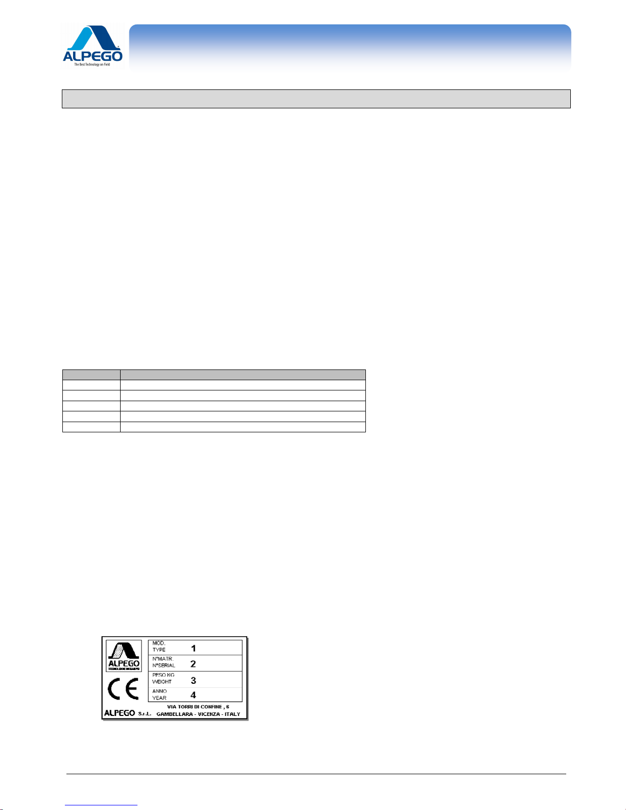
1.4. IDENTIFICATION OF THE MACHINE.................................................................................................................1
2. TECHNICAL SPECIFICATIONS................................................................................................................................2
2.1. DESCRIPTION.....................................................................................................................................................2
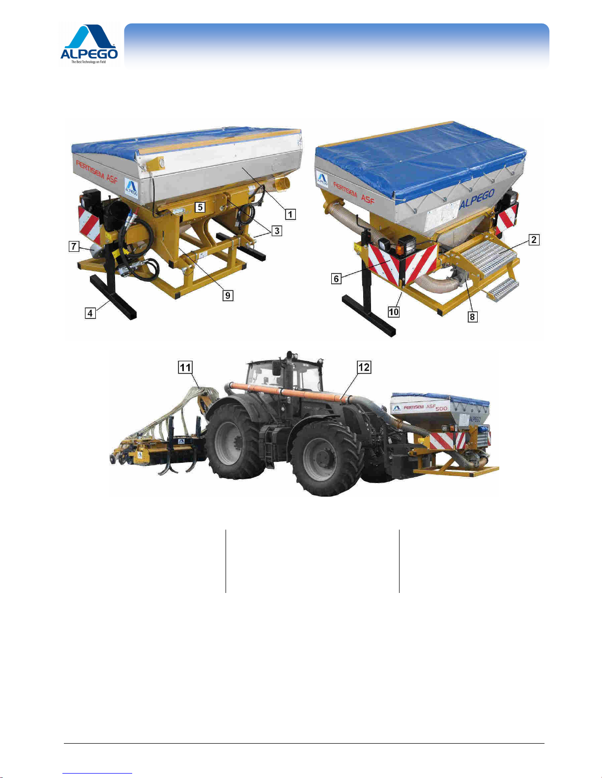
2.2. IMPLEMENT COMPONENTS .............................................................................................................................3
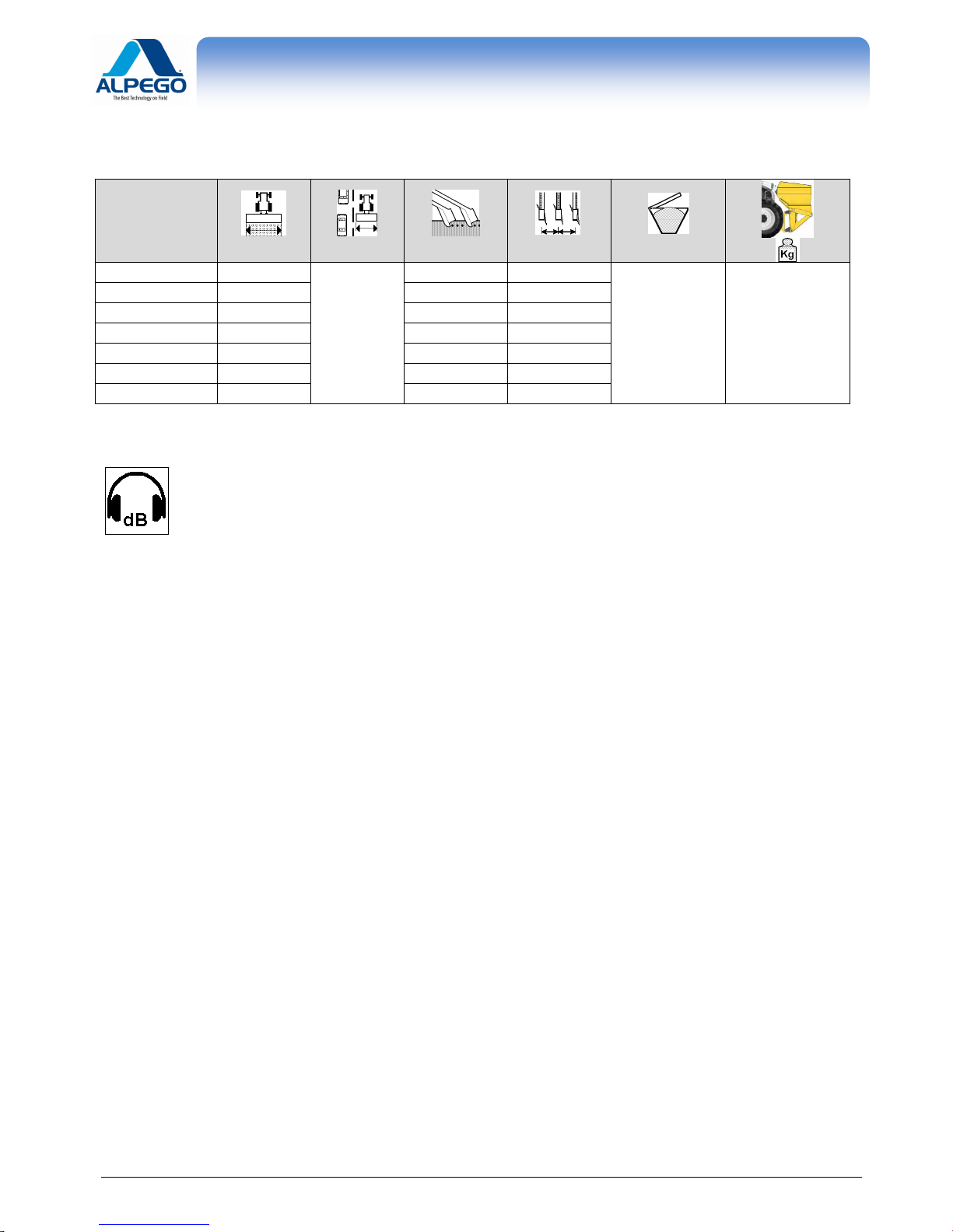
2.3. CHART OF TECHNICAL DATA...........................................................................................................................4
2.4. SOUND LEVEL....................................................................................................................................................4
3. SAFETY REGULATIONS ..........................................................................................................................................5
3.1. USE THE MACHINE SAFETY.............................................................................................................................5
3.2. HYDRAULIC CONNECTIONS.............................................................................................................................6
3.3. ASSEMBLY OF ELECTRIC AND ALECRONIC INSTRUMENTS AND COMPONENTS ...................................7
3.4. CARRYING OUT MAINTENANCE SAFETY.......................................................................................................7
3.5. TRAVELLING ON ROADS...................................................................................................................................8
3.6. CLOTHING...........................................................................................................................................................8
3.7. ECOLOGY............................................................................................................................................................8
3.8. SAFETY SIGNALS...............................................................................................................................................8
4. INSTALLATION ........................................................................................................................................................9
4.1. TRANSPORT O ...................................................................................................................................................9
4.2. LIFTING..............................................................................................................................................................10
4.3. CONNECTING THE FRONT HOPPER TO THE TRACTOR............................................................................10
4.4. RADAR INSTALLATION....................................................................................................................................11
4.5. ASSEMBLING THE SEEDER BAR ..................................................................................................................11
4.6. FITTING THE SEED COVERING HARROW ....................................................................................................11
4.7. ASSEMBLING THE SEEDER PIPES...............................................................................................................12
4.7.1. ASSEMBLYING THE SEEDING PIPES ON THE POWER HARROW.......................................................16
4.8. CONNECTING SYSTEM BETWEEN FRONT HOPPER AND REAR DISTRIBUTION HEAD.........................17
4.8.1. MAIN COMPONENTS.................................................................................................................................17
4.8.2. INSTALLATION OF THE CONNECTING SYSTEM ON THE TRACTOR..................................................18
4.8.3. CONNECTING THE HOPPER WITH THE IMPLEMENT...........................................................................19
4.9. CHECK OF THE TRACTOR STABILITY AND ITS LIFTING POWER..............................................................20
5. INSTRUCTIONS FOR USE......................................................................................................................................21
5.1. OPERATION OF THE BLOWER.......................................................................................................................21
5.1.1. HYDRAULIC CONNECTION WITH THE TRACTOR .................................................................................21
5.1.2. ADJUSTEMENT OF THE OIL FLOW WITHOUT A VARIABLE DISPLACEMENT PUMP........................22
5.2. DISTRIBUTION..................................................................................................................................................22
5.3. UNHITCHING THE FRONT HOPPER...............................................................................................................22
5.4. UNHITCHING THE REAR IMPLEMENT ...........................................................................................................22
6. MAINTENANCE .......................................................................................................................................................23
6.1. CHECKS AND CONTROLS...............................................................................................................................23
6.2. LUBRICATION...................................................................................................................................................23
6.2.1. LUBRICATING THE GREASERS...............................................................................................................23
6.3. END OF SEASON OPERATIONS.....................................................................................................................24
7. ACCESSORIES........................................................................................................................................................25
7.1. ROW MARKING DISC.......................................................................................................................................25
7.2. PRE-SPROUTING DISCS.................................................................................................................................25

OWNER'S MANUAL OF PNEUMATIC FERTILIZER
SPREADER ASF
Old CodQ00A00140
New Cod. -
Copyright ©2009 della Alpego srl ® -Tutti i diritti sono riservati. È espressamente vietata la ristampa o l’uso non autorizzato per iscritto da parte di Alpego srl
7.3. HYDRAULIC SEEDING EXCLUSION ...............................................................................................................26
7.4. DEPTH LIMITING WHEEL.................................................................................................................................26
7.5. HOPPER EXTENSION......................................................................................................................................26

OWNER'S MANUAL OF PNEUMATIC FERTILIZER
SPREADER ASF
Old Cod.Q00A00140
New Cod. -
GENERAL INFORMATION
- 1
Copyright ©2009 della Alpego spa ® -Tutti i diritti sono riservati. È espressamente vietata la ristampa o l’uso non autorizzato per iscritto da parte di Alpego spa
1. GENERAL INFORMATION
1.1. PURPOSE OF THE MANUAL
This manual was created by the machine producer and is an integral part of the documentation that accompanies the
machine.
The manual defines the purpose for which the machine was produced, it establishes correct machine application and
limits of use.
The constant application of the indications given in this manual guarantees the safety of those who use the machine,
as well as working economy and longer machine duration.
This manual has been divided into sections. To make it easier to find a specific topic, consult the initial index.
The images that appear in this manual are given as an example. Even if substantially different from the machine you
possess, the safety and information are guaranteed.
1.2. DOCUMENTS ACCOMPANYING THE MACHINE
The following documents should be supplied with the machine:
•User and maintenance manual
•Spare parts catalogue
•EC Conformity Declaration
The machine may be supplied complete with different options/fittings. For the assembly and the use of those check
the specific manuals supplied with the documents of the machine.
CODE
DESCRIPTION
D16555
Owner’s Manual of the
DOSAL metering unit
Q00A00129
Owner’s Manual of the
row
-
marking discs
Q00A00134
Owner’s Manual of the
seeding bar
Q00A00132
Owner’s Manual of the
foll
owing harrow
D15686
Owner’s Manual of the
“Super Plus” Computer
1.3. WARRANTY
When delivered, make sure that the machine and any accessories were not damaged during transport.
Any complaints should be presented in writing within 6 days from the date of delivery.
GUARANTEE FORFEITURE
The guarantee is rendered null and void immediately if:
•there is a manoeuvring error
•If the universal joint has not been sufficiently maintained (see owner’s manual of universal joint)
•If the maximun power limit allowed is exceeded (see technical data on the table 2.3)
•the instructions described in this manual are not followed
•original spare parts are not used
•any modification is made to the machine without having obtained authorisation from the manufacturer.
1.4. IDENTIFICATION OF THE MACHINE
On the left front section of the seed box there is a machine identification plate which carries the following information:
1. Machine type
2. Serial number
3. Maximum weight of the machine with roller
4. Year of production
The indicated weight refers to the machine complete with
standard shoe coulters.

OWNER'S MANUAL OF PNEUMATIC FERTILIZER
SPREADER ASF
Old Cod.Q00A00140
New Cod. -
TECHNICAL SPECIFICATIONS
- 2
Copyright ©2009 della Alpego spa ® -Tutti i diritti sono riservati. È espressamente vietata la ristampa o l’uso non autorizzato per iscritto da parte di Alpego spa
2. TECHNICAL SPECIFICATIONS
2.1. DESCRIPTION
•
The seeder/fertilizer spreader mod. ASF must only be used for working agricultural lands. Any other use differing
from the one described in this manual can damage the machine and be dangerous for the operator.
•
The seeder/fertilizer spreader mod. ASF can be used with other equipment for working the soil, but only with the
addition of a special assembly kit.
•
The seeder/fertilizer spreader mod. ASF is ideal for sowing cereal: wheat, barley, rye, oats, rice; fine seeds and
fodder: rape, clover, alfalfa; and for big seeds: soya, peas.
•
The seeder/fertilizer spreader mod. ASF is suited for the distribution of various types of fertilizers.
•
The seeds are deposited in the soil by coulter organs, sock or discs, and are distributed continuously. A special
revolving metering unit driven by a wheel which adheres to the ground regulates the quantities to be distributed.
•
The seeds are distributed and transported to the coulters by compressed air that is produced by a fan. The fan is
moved by the tractor power takeoff, or hydraulically as in the Plus version.
•
The disc or sprint sock coulter is mounted on a super-elastic support that gives excellent depth and pressure
control on the soil and regulates the height of the seed bar.
For the development and the construction of this implement the following guidelines of the Standard 98/37CE have
been studied and applied:
UNI EN 14018 UNI EN 1553 UNI EN 982 ISO 11684 ISO 3757-2
The seeder/fertilizer spreader ASF has been built in view of combining it with power harrows of the “ALPEGO” type,
since this combination guarantees the observance of Standard EN 708.
The machine will work well if used correctly and if maintenance is carried out regularly. Users are strongly advised to
scrupulously observe the instructions given in this manual in order to prevent any inconvenience that could impair
good machine operation and its durability.
Users must follow the instructions given in this manual because the Manufacturer cannot be held responsible for any
damage or injury caused by negligence and the non-observance of such instructions.
The Manufacturer assures complete assistance with regard to immediate and accurate technical service, a well as
anything that may be necessary for a better operation and maximum performance of the implement.

OWNER'S MANUAL OF PNEUMATIC FERTILIZER
SPREADER ASF
Old Cod.Q00A00140
New Cod. -
TECHNICAL SPECIFICATIONS
- 3
Copyright ©2009 della Alpego spa ® -Tutti i diritti sono riservati. È espressamente vietata la ristampa o l’uso non autorizzato per iscritto da parte di Alpego spa
2.2. IMPLEMENT COMPONENTS
1. Hopper
2. Ladder for filling ladder
3. 3-point hitch
4. Supporting stands
5. Electric control panel
6. Front lights
7. Fan
8. Metering unit
9. Electric motor
10. Radar
11. Distribution head
12. Seed conveying pipe

OWNER'S MANUAL OF PNEUMATIC FERTILIZER
SPREADER ASF
Old Cod.Q00A00140
New Cod. -
TECHNICAL SPECIFICATIONS
- 4
Copyright ©2009 della Alpego spa ® -Tutti i diritti sono riservati. È espressamente vietata la ristampa o l’uso non autorizzato per iscritto da parte di Alpego spa
2.3. CHART OF TECHNICAL DATA
MODEL.
cm
cm
N °
cm
dm
3
ASF - 300 300
250
24 12.5
1400 600
ASF - 350 350 28 12.5
ASF - 400 400 32 12.5
ASF - 450 450 36 12.5
ASF - 500 500 40 12.5
ASF - 600 (40) 600 40 15
ASF - 600 (48) 600 48 12.5
2.4. SOUND LEVEL
If the tractor is equipped with a cabin, the sound level will depend on the soundproofing level of the
cabin itself. If the tractor does not have a cabin or is used with the windows open, the noise level
emitted by the machine while working and measured at a distance of 200 mm. from the rear window
exceeds 85 dBa. It is therefore advisable to use protective earmuffs as indicated in the regulations
of different countries.

OWNER'S MANUAL OF PNEUMATIC FERTILIZER
SPREADER ASF
Old Cod.Q00A00140
New Cod. -
SAFETY REGULATIONS
- 5
Copyright ©2009 della Alpego spa ® -Tutti i diritti sono riservati. È espressamente vietata la ristampa o l’uso non autorizzato per iscritto da parte di Alpego spa
3. SAFETY REGULATIONS
3.1. USE THE MACHINE SAFETY
•Read the user and maintenance manual carefully before starting-up, before using the machine and before
carrying out maintenance on the equipment.
•The manufacturer cannot be held responsible for injuries caused to people and animals, or damage caused
because the safety regulations have not been observed by the user.
•The machine cannot be used for different purposes other than those expressly indicated in this manual.
•It is forbidden for people to drive the tractor if they do not have a suitable driving licence, if they do not have the
necessary experience, or if they are not in good health.
•Examine the adhesive labels on the machine carefully, and make sure you follow their indications.
•While manoeuvring, do not allow people or animals to approach within the working range of the machine.
•While working do not allow people, animals or objects to approach within the area where sods and stones are
thrown out by the machine.
•It is absolutely forbidden to enter the space between the tractor and the
machine to operate the external controls of the hydraulic lift.
•Always remain seated in the tractor driver's seat. Only leave the driver's seat
when the tractor power take off has been disengaged and the handbrake has
been pulled.
•During working stops switch off the engine, lower the implement to the ground, disengage the tractor power
takeoff and pull the tractor handbrake.
•Make sure never to work if guards have been removed.
•Do not let the implement run when raised (out of the ground).
•While working do not take turns while the machine is set in the ground.
Never work in reverse gear.
•Always lift the implement when changing direction and reversing.
•During transportation, or whenever the machine has to be lifted, the tractor lift should be regulated so that the
machine is kept at a maximum distance of not more than 45 cm. off the ground. Do not circulate on roads if the
machine is dirty with soil, grass or other materials which may soil the roads and/or cause traffic problems . Do
not lower the machine to the ground abruptly , but rather do so slowly so as to allow the tines to penetrate into
the soil gradually .
•Unless you follow this rule, strong stressing forces will be exerted on all the components of the machine and they
may compromise its integrity
•While driving on the road with the machine lifted off the ground, put the lever controlling the hydraulic lifting
mechanism of the tractor in the blocked position.
•The implement and its accessories for transit on public roads must be complete with suitable signs and safety
guards

OWNER'S MANUAL OF PNEUMATIC FERTILIZER
SPREADER ASF
Old Cod.Q00A00140
New Cod. -
SAFETY REGULATIONS
- 6
Copyright ©2009 della Alpego spa ® -Tutti i diritti sono riservati. È espressamente vietata la ristampa o l’uso non autorizzato per iscritto da parte di Alpego spa
•Do not work in terrains or places which may compromise the stability of the implement.
•Use only the universal joint supplied by the manufacturer, complete with the safety device against overloads.
•The protection device of the universal joint must always be in good working order and has to be checked at
regular intervals and secured by means of chains in order to prevent it from revolving.
•Always disconnect the power takeoff when the universal joint forms an angle
exceeding 15°, see picture.
•The seed-drill may transport chemicals used to coat the seeds. Therefore, never
allow people, children or pets to approach the seed-drill.
•Nobody can be allowed to approach the hoppers or to attempt to open them while the seed-drill is working of
about to be started
3.2. HYDRAULIC CONNECTIONS
•Make sure that the hydraulic systems of the machine and the tractor are not under pressure when you connect
the hydraulic hoses to the hydraulic system of the tractor.
•When linking functional connections, for example between the tractor and the machine tool, colour mark all the
intakes and plugs to avoid mistakes. Connection mistakes can cause accidents.
•The hydraulic system is pressurised. To avoid accidents, use suitable auxiliary instruments if you have to search
for leaks.
•Never exceed the pressure indicated for the oleodynamic system.

OWNER'S MANUAL OF PNEUMATIC FERTILIZER
SPREADER ASF
Old Cod.Q00A00140
New Cod. -
SAFETY REGULATIONS
- 7
Copyright ©2009 della Alpego spa ® -Tutti i diritti sono riservati. È espressamente vietata la ristampa o l’uso non autorizzato per iscritto da parte di Alpego spa
3.3. ASSEMBLY OF ELECTRIC AND ALECRONIC INSTRUMENTS AND COMPONENTS
•The machine is equipped with electronic components which may interfere on other instruments through electro-
magnetic transmission. Said interferences may constitute a risk to people, if the following safety instructions are
not carefully followed.
•If the assembly of electric or electronic instruments and/or components is done at a later date, the user will have
to test, under his own responsibility if the new addition causes any irregularity to the electronic of the tractor or to
other electronic components.
•In particular it will be necessary to make sure that the electric or electronic components which are added at a later
date comply with the guidelines CEM 891336/CEE in their most recent valid version and they carry the CE brand
of approval.
•In case of a later addition of mobile communication systems (i.e. radio, phone etc.) the following requirements
must also be taken into account:
1. Only instruments which comply with the national valid standards may be installed (for instance the
BZT homologation for Germany)
2. The instruments must be installed so they cannot be removed.
3. The use of mobile or portable instruments inside the vehicle is allowed exclusively through a
connection with a fixed external antenna.
4. The transmitter is to be installed far away from the electronic of the vehicle.
5. When the antenna is installed make sure that it is properly installed with a good earth connection
between the antenna and the earth of the vehicle.
For the laying of the cables, the assembly and the maximum power absorption allowed see also the directions
given by the manufacturer of the machine.
3.4. CARRYING OUT MAINTENANCE SAFETY
•Do not allow unauthorised people to carry out maintenance or tamper with the machine in any manner.
•Maintenance and repairs should be carried out in suitably equipped workshops.
•Always use original accessories and spare parts to respect the manufacturer’s requirements. Not using original
parts and accessories renders the guarantee null and void and can cause function irregularities that prejudice
machine safety.
•When carrying out any operation on the machine always disable the tractor power takeoff, insert the handbrake,
remove the ignition key and make sure that nobody boards the tractor

OWNER'S MANUAL OF PNEUMATIC FERTILIZER
SPREADER ASF
Old Cod.Q00A00140
New Cod. -
SAFETY REGULATIONS
- 8
Copyright ©2009 della Alpego spa ® -Tutti i diritti sono riservati. È espressamente vietata la ristampa o l’uso non autorizzato per iscritto da parte di Alpego spa
3.5. TRAVELLING ON ROADS
If necessary, the machine can be transported on the roads while hitched to the tractor. The operator must check,
compare and adapt the implement so that it fully complies with the Highway Code in force in the country of use. Bear
in mind the following recommendations:
1. Comply with the instructions in this manual when you hitch the machine to the tractor;
2. The machine must remain blocked and raised from the ground during transport.
3. You must take all possible precautions and comply with the pertinent laws in order to safeguard
yourselves and others.
4. Projecting parts and those beyond the width of the tractor must be fitted with the relative protections.
5. The entire implement must be equipped with its own lighting system complete with flashing lights and
indicators.
6. Warning boards to indicate the projecting parts of the implement must be affixed where necessary.
7. The braking distance and steering capacity of the tractor are influenced by the weight of the machine
hitched to its power lift. When driving round bends, take great care and allow for the action of the
centrifugal force that shifts the machine’s center of gravity.
8. Comply with the load limits on the axles.
9. Bear in mind the limits imposed by the overhang and projection from the sides of the tractor.
3.6. CLOTHING
Always wear protective clothing without any loose parts that could entangle in the moving components. In addition
always remove watches, rings, necklaces etc. that could cause the same danger. Gather long hair into a ponytail.
If requested by current user country norms, the machine operator should wear
suitable protection systems: goggles, gloves, helmet, shoes, etc
3.7. ECOLOGY
Respect the regulations in your country regarding the use and disposal of lubricating products, maintenance
operations and machine cleaning. Carefully follow the instructions given on the packaging of the products used.
Respect current standards for machine scrapping.
3.8. SAFETY SIGNALS
The various adhesives on the machine are there to highlight the source of danger. Observe them carefully and
follow the indications for using the machine safely. The labels should be kept clean and be legible – if damaged they
should be replaced.
FIGURE
CODE
INDICA
TIONS
D02612
You MUST read the user and maintenance
manual and the safety instructions before using
the equipment. The manual and the instructions
must be followed during use
D02627
Indicates the hooking point for machine
transportation

OWNER'S MANUAL OF PNEUMATIC FERTILIZER
SPREADER ASF
Old Cod.Q00A00140
New Cod. -
INSTALLATION
- 9
Copyright ©2009 della Alpego spa ® -Tutti i diritti sono riservati. È espressamente vietata la ristampa o l’uso non autorizzato per iscritto da parte di Alpego spa
D02624
Indicates the danger caused by pressurised oil if
the hydraulic pipes break. Consult the instruction
manual before repairing the hydraulic system
D02608
Indicates the danger of entanglement while
working on the universal joint shaft. Do not
approach the shaft while it is rotating
D02615
Indicates the need to switch off the tractor and
remove the ignition key during maintenance
operations
D02616
Indicates the position of a support leg that must
always be locked into place when the machine is
not being used to keep the machine stable
D10238
Indicates that the hydraulic hose driving the ½”
turbine must be connected to the tractor
hydraulic connection having priority delivery
D10239
Indicates that the hydraulic ¾” return hose must
be connected to the tractor oil tank, and that the
return counter-pressure can not exceed 5 Bar
4. INSTALLATION
4.1. TRANSPORT O
The machine can easily be transported even over long distance with suitable means of transportation: lorries,
trailers, train cars etc.
The loading and unloading of the machine can be rather dangerous operations, unless they are
performed with the utmost care: have all unauthorized personnel leave the area; clear and
circumscribe the loading area; check that the available means of transportation are in good
working order and strong enough for the job at hand.
It is also necessary to make sure that the area of operation is free and that there is enough escape
space, i.e. a free and safe area where it is possible to move quickly should the machine fall down.
Said operations are to be performed exclusively by personnel trained to perform this type of work.
Before beginning the loading operation make sure that the available means is certified for this type of transportation
and that it is strong enough to support the weight of the machine. To this end see CHART OF TECHNICAL DATA
(see Par. 2.3) for the weight of the machine.
This chart is also useful to check the possibility of transit of the machine through narrow passages.

OWNER'S MANUAL OF PNEUMATIC FERTILIZER
SPREADER ASF
Old Cod.Q00A00140
New Cod. -
INSTALLATION
- 10
Copyright ©2009 della Alpego spa ® -Tutti i diritti sono riservati. È espressamente vietata la ristampa o l’uso non autorizzato per iscritto da parte di Alpego spa
4.2. LIFTING
The Lifting and moving operations must be performer with means
strong enough to carry the weight of the machine and by personnel
trained in this type of work. If it becomes necessary to lift the machine,
hook the machine as shown in the picture and move it: during this operation the
machine should not be lifted by more than 200 mm. from the ground. In order to
avoid damages to the hopper metal plates, use approved lifting belts
4.3. CONNECTING THE FRONT HOPPER TO THE TRACTOR
This operation must be carried out on a horizontal surface, with the seed-drill in a stable position on
its support legs
The front hopper is supplied STANDARD with a cat. 2 hitch for tractors with front lifter. If your tractor does not have
this device, you can fix the box to the tractor ballast frame, but only after the Manufacturer has carried out a technical
check.
When the hopper has been connected solidly to the tractor, make sure that the equipment is perpendicular to the
ground. If necessary, you can use the upper arm to correct the position of the equipment.
Support the hopper with the tractor lift and lift the legs toward the tractor. Block them into position by inserting the pin
into the corresponding bushing (see pct. below)
If your tractor does not have this device, you can fix the box to the tractor ballast frame, but only after the
Manufacturer has carried out a technical check.

OWNER'S MANUAL OF PNEUMATIC FERTILIZER
SPREADER ASF
Old Cod.Q00A00140
New Cod. -
INSTALLATION
- 11
Copyright ©2009 della Alpego spa ® -Tutti i diritti sono riservati. È espressamente vietata la ristampa o l’uso non autorizzato per iscritto da parte di Alpego spa
4.4. RADAR INSTALLATION
The radar is to be positioned as follows on the frame supporting the hopper:
1. Attach the support Ato the lower frame of the hopper by means of the U-bolts clamps C
2. Attach the radar Bto the support A.
There is only one possible position of the radar on its support, while the latter can be displaced along the slanted
pipe of the frame, so as to guarantee, in the working position, a height from the ground which can vary between 0.4
and 1 m.
In order for the radar to work at its ideal position of ± 37°the hopper must be parallel to the grou nd
while it is working.
4.5. ASSEMBLING THE SEEDER BAR
The operation should be carried out on a horizontal surface,
with the harrow in a stable position and the seed bar positioning
legs inserted.
For the assembly of the seeding bar follow the directions given in the relevant
Owner’s Manual.
4.6. FITTING THE SEED COVERING HARROW
Then the seeder is delivered, the seed covering comb is supplied separately from the machine.
Together with the documents of the machine you will find also the Instructions Manual concerning the
following harrow: it is mandatory to follow it scrupulously.

OWNER'S MANUAL OF PNEUMATIC FERTILIZER
SPREADER ASF
Old Cod.Q00A00140
New Cod. -
INSTALLATION
- 12
Copyright ©2009 della Alpego spa ® -Tutti i diritti sono riservati. È espressamente vietata la ristampa o l’uso non autorizzato per iscritto da parte di Alpego spa
4.7. ASSEMBLING THE SEEDER PIPES
When the seeder/fertilizer spreader is delivered, the seeding pipes are not connected with the seeding
bar. Depending on the bar which will be used (Suffolk or disc coulters) it is mandatory to connect all
the pipes and to follow the relevant directions below
1. Position the seeder pipes following the drawing:
Make sure that the arrow on the distributor is in the direction of the hopper
ASF – 300
rigid
ASF - 350
rigid

OWNER'S MANUAL OF PNEUMATIC FERTILIZER
SPREADER ASF
Old Cod.Q00A00140
New Cod. -
INSTALLATION
- 13
Copyright ©2009 della Alpego spa ® -Tutti i diritti sono riservati. È espressamente vietata la ristampa o l’uso non autorizzato per iscritto da parte di Alpego spa
ASF - 400
rigid
ASF - 400
folding

OWNER'S MANUAL OF PNEUMATIC FERTILIZER
SPREADER ASF
Old Cod.Q00A00140
New Cod. -
INSTALLATION
- 14
Copyright ©2009 della Alpego spa ® -Tutti i diritti sono riservati. È espressamente vietata la ristampa o l’uso non autorizzato per iscritto da parte di Alpego spa
ASF - 450
folding
ASF - 500
folding

OWNER'S MANUAL OF PNEUMATIC FERTILIZER
SPREADER ASF
Old Cod.Q00A00140
New Cod. -
INSTALLATION
- 15
Copyright ©2009 della Alpego spa ® -Tutti i diritti sono riservati. È espressamente vietata la ristampa o l’uso non autorizzato per iscritto da parte di Alpego spa
ASF - 600 (40 uscite)
folding
ASF - 600 (48 uscite)
folding
Table of contents
Other Alpego Farm Equipment manuals