manuals.online logo
Brands
  1. Home
  2. •
  3. Brands
  4. •
  5. Alpha Communications
  6. •
  7. Intercom System
  8. •
  9. Alpha Communications TekTone Tek-COM PK724 Series User manual

Alpha Communications TekTone Tek-COM PK724 Series User manual

Tek-COM® PK724 Series
Installation Instructions
IL537
Section B
Rev. 12 - 09/2004
APPLICATION
TheTek-COM®Intercom provides fast, natural-voice, room-
to-room communications. The MONITOR function permits
listening to any room but may be released to obtain full
privacy. Door answering is made simple by an automatic,
hands-free reply circuit. A number of optional accessories
are available to provide a complete home signaling and
communications system.
PROCEDURE
1. Read the installation instructions for each unit to deter-
mine equipment locations and installation methods.
2. Install the housings and wiring.
3. Install the equipment.
4. Check all wiring and connections.
5. Apply power and check system operations.
HOUSING INSTALLATION AND
EQUIPMENT LOCATION
Inside Stations
Locate stations where needed at a convenient speaking
height—about 4.5' (1.4 m) from the finished floor. Do
not install stations back-to-back or on a common wall
between rooms. Install IH102 rings for IR704B/BD
stations as shown in Figure 1a. Reverse the ring for
mountingonfinishedwalls.InstallIH110R housings with
IR804A stations as shown in Figure 1b.
Outside Stations
Locate door stations at a convenient speaking height on
exterior walls near an entrance. The front of the housing
must be flush with the finished wall to ensure weather
protection.InstallIH101housingswithOR101,OR501B,
and OR502 stations (Figure 1c). Use standard single-
gang rings (Figure 1d) for mounting OR601, OR603,
and OR604AW stations. Install OR501S or OR502S for
surface mount with no housings required.
Amplifier
Theamplifierisdesignedtobesurfacemountedandmust
be located away from any source of direct heat or cold
and in an accessible location. Keep it at least 3' (1 m)
away from transformers, light dimmers, and other
electrical devices or wiring.
Transformer
The SS105B plug-in type transformer must be provided
with an electrical outlet at a convenient location, and
should be located within 50' (15 m) of the amplifier. If
the SS102A pigtail type transformer is used, it may be
installed on the fuse panel or other accessible source of
117VAC, preferably within 50' (15 m) of the amplifier.
Accessories
Optional accessories are to be installed where needed.
The DO-001A electric door release is installed in the door
jamb in place of the regular door strike plate.
7.82"
5.35"
Figure 1b
IH110R Figure 1d
Single Gang Box
4.1"
5.45" 5.95
"
4.7"
Figure 1a
IH102
3.85"
5.55"
Figure 1c
IH101
Figure 1 — Station Housings
ALPHA COMMUNICATIONS®• 42 Central Drive •Farmingdale, NY 11735-1202
Toll-Free Technical Line: 1-800-666-4800 • Phone: (631) 777-5500 • Fax: (631) 777-5599
Website: www.alpha-comm.com • Email: [email protected]
Page 2 • IL537 Tek-COM®Installation Instructions
WIRING INSTALLATION
Route all cables away from AC power wiring, transformers,
fluorescent lighting, light dimmers, or other electrical
devices. If AC/RF interference is a concern, use shielded
cablesthroughoutthesystem.Protectthecablesfromdamage
during installation.
Inside Stations
Run two twisted pair #22 cables from station to station
and to the amplifier. The cable length is limited by the
number of stations per cable, as shown in Figure 2.
Additional cables may be used to serve other stations
(see Figure 3).
Outside Stations
Run3conductor#22 twisted cable from the outside station
to the amplifier (Figure 3). The maximum cable length is
150' (45 m) and the maximum number of stations is two.
Music Input
Run2 conductor #22 shielded cable fromthe music input
source to the amplifier.
Door Release
IR704BD inside stations must be used if door release
functionis needed. Run 2 conductor#18cablefrom inside
station to inside station and to the amplifier. Run 2
conductor #18 cable from the door release location to
the amplifier. Keep cables away from station wiring.
CONNECTIONS
Before making the connections, make certain that the wires
are free from shorts or grounds. Make the connections as
shown in Figure 4 and as detailed in the following
instructions.
Inside Stations
1. Connect terminals 1 and 2 on the inside stations to
terminals 1 and 2 of other inside stations, and to
terminals 1 and 2 on the PK724 amplifier.
2. Connect terminals 3 and 4 on the inside stations to
terminals 3 and 4 of other inside stations, and to
terminals 3 and 4 of the amplifier. Do not reverse the
polarity of these wires.
3. If an electric door release is used, connect terminals
D and T on IR704BD inside stations to terminals D
andTonotherIR704BDstations.Seethe door release
section below for further connections.
Outside Stations
1. Connect the speaker terminals of OR501B/OR501S/
OR502/OR502S/OR603 outside stations to terminals
AandGontheamplifier.Connectthe station terminal
Z to terminal F on the amplifier if the two-tone FRONT
chime is used, or to terminal R on the amplifier if the
single REAR tone is needed. Add the jumper shown in
Figure 4a only for OR501B and OR502 stations.
2. For the installation of OR101 and OR601 stations,
connect the red wire to terminal A and the black wire
to terminal G on the amplifier.
3. For the installation of OR604AW stations, connect
terminal A to terminal A and terminal G to terminal
G on the amplifier. Connect the terminal labeled Z to
terminal F on the amplifier if the two-tone FRONT
chime is desired, or to the R terminal if the single
REAR tone is desired. Finally, if lighted push button is
desired, connect the supplied 680 ohm resistor
(part #RC025) between LP and Z.
Transformer
1. Connect the transformer’s 16 VAC terminals to the
amplifier’s T and S terminals. Do not use this
transformer to power an electronic chime, security
alarm, or other device.
2. Donotplug the SS105B transformer into an electrical
outlet or connect the SS102A transformer primary to
117 VAC until the entire installation is complete and
checked out.
Music Input
1. Connect the music input source to terminals M and G
on the amplifier, or connect to a VC704 stereo output
adapter.
Door Release
1. Connect one wire coming from the door release to
the amplifier terminal S.
2. Connect the other wire from the door release to
terminal D on the IR704BD station.
3. Connect a wire from the IR704BD station T terminal
to terminal T on the amplifier.
FINISHING THE INSTALLATION
Install the stations in their housings, being careful not to
overtighten any screws. Install the amplifier in its
predetermined location, and install any accessory devices
as needed. The SS105B transformer may now be plugged
into an outlet, or if an SS102A transformer is used, the
primary may be connected to 117 VAC. Be sure to observe
local electrical codes.
# of Stations Length (ft/m)
1 600 / 180
2 300 / 90
3 160 / 50
4 80 / 25
Maximum number of stations per cable: 4
Maximum number of stations per system: 20
NOTE: If more than 10 stations are installed on the
system, only 10 may be turned fully ON at one time.
Figure 2 —Maximum Cable Length Chart
IL537 Tek-COM®Installation Instructions • Page 3
Figure 4 —Connections Diagram
NOTES:
1. Use twisted pair wiring where shown. Terminals T and D (for the door release function) are found on IR704BD stations only.
2. For OR101 and OR601 stations, connect the red wire (speaker +) to terminal A on the PK724 amplifier and the black wire
(speaker -) to terminal G. For a generic outdoor station (such as in Fig. 4b), connect the speaker wires in the same manner
andconnectonewirefromthepushbuttontoeitherterminalForterminalR,andanotherwirefromthebuttontotheCterminal
on the amplifier.
3. If shielded cable is used, connect the drain wire to the C terminal on the amplifier. Shielded cable is recommended for the
music input.
Figure 3 —Wiring Diagram
NOTES:
1. Use an IR704BD indoor station when a door release is needed
(wiring shown as dotted lines). Route the door release wiring
away from station wiring.
2. UseanOR603,OR501B,OR501S,OR502,orOR502Soutdoor
stationifthechime(call)signalisneeded.Ifnochimeisneeded,
use an OR601 or OR101 outdoor station (without push button).
Use an OR604AW outdoor station if a lighted push button is
desired.
IndoorStations
#22
2 Twisted Pair Amplifier
OutdoorStations
#22
3 Conductor
Twisted
#18
2 Conductor
Music Source
Transformer
#18
2 Conductor
DO-001A
#22
2 Conductor
Twisted
(Optional)
#18
2Conductor
SS102A
IR704BD IR704B
IR804
IR704B
IR804
PK724
OR603
(Optional)
SS102A or SS105B
Transformer
DO-001A Door Opener
Music
Source
Outdoorstations
OR603
To same terminals of
additionalindoor stations
IR704B/BD or IR804
IndoorStations
4321
D
T
Z
G
IR704BD
OR
VC704
117 VAC
PK724
C(Black)
T(Red)
S(Red / White)
1(Orange)
2(Orange / White)
F(Yellow)
R(Green)
M(White)
A(Blue)
3(Brown)
4(Brown / White)
G(Gray)
G(Gray)
INTERCOM
AMPLIFIER
A
Generic Outdoor Station
Speaker
Lighted /
Non-Lighted
Push Button
A
G
C
F or R
Figure 4b
#22 Twisted Pair
OR501B/OR501S/OR502/OR502S/OR502SS
Figure 4a
Add jumper as shown
A G
ZW
Figure 4c
OR604AW
Page 4 • IL537 Tek-COM®Installation Instructions
TEST AND CHECKOUT
1. At all inside stations, make certain the MONITOR button is
in the OFF position (press the INSIDE button to disengage
theMONITORfunction).TurnthevolumecontrolfullyON.
If more than 10 stations are installed on the system, only
10 may be turned fully ON at one time.
2. Checkeachunitinthesystemforoperationinaccordance
with the operating instructions.
3. Iffeedbackoccursbetweenstations(squealing,howling,
etc.), reduce the volume on the stations. The amplifier
volume may be readjusted as necessary with a small
screwdriver or television tuning tool.
4. Ifthemusicinputisused,adjustthecontrolvolumeatthe
source of the music as needed. Excessive music input
volume will cause distortion (see Specification Sheet
IL538).
NOTE: The TekTone®warranty is void if this system is
installed or used in any manner other than as described in
this Tek-COM® Installation Instruction—IL537.
OPERATING INSTRUCTIONS
Inside Stations
Call:Press and hold the INSIDE talk button and speak in a
normal voice. The call will be heard at all inside stations
that are turned ON and not switched to MONITOR. Release
the button to listen for the reply.
Reply: Push the INSIDE talk button and speak in a normal
voice. Release the button after speaking.
Answer the Door Station: Push and hold the OUTSIDE talk
button and speak in a normal voice. Release the button
to hear the reply. The reply is automatic and does not
require the operation of any controls.
Monitor a Room: Push the MONITOR button on the room
station where listening is desired. Sounds from that room
will be heard at any inside station that is turned ON. A
maximumofthreestationsmaybemonitoredat one time.
Privacy:Release the MONITOR button to the OFF position
by partially pressing the INSIDE button, and it will be
impossible to listen to that station from other locations.
Turn the VOLUME control OFF for complete privacy.
Outside Stations
Call: Push the button on the outside station to sound a
call tone. The call tone will be heard on all inside stations
that are turned ON.
Music Input
Operatethe music system according to themanufacturer’s
instructions. Music will be heard on all inside stations
that are turned ON and not switched to MONITOR. The
music will automatically be silenced when the MONITOR
function at any station is in operation. To operate the
intercom system without music being heard on the
stations, turn the volume on the music source control
panel to the OFF position.
Door Release
If an electric door release is installed, it may be operated
fromany IR704BD station by pushing the button marked
DOOR. The door release will buzz while operating,
indicating permission to enter.
TROUBLESHOOTING
Ifthesystemfails to operate as required, review the operating
instructions. If the equipment fails to operate as indicated in
the instructions, check the following.
Entiresystemdead:16VAC at transformer secondary,wiring
between transformer and amplifier, connections at amplifier
terminals T and S, 117 VAC at transformer primary.
Nosound from onespeaker: Speaker volume turned down,
MONITOR button engaged, wiring to terminals 3 and 4 of
station’s amplifier.
Lowvolume:Speaker volume set too low, amplifier volume
set too low.
Squealing or howling: Amplifier volume set too high,
stations installed too close or on a common wall between
rooms, twisted pair wiring not used.
Unable to talk to door: Connections to outside stations,
wiring to A and G amplifier terminals, volume set too low.
Unable to listen to door: Wiring to terminals 1 and 2 of
amplifier and stations (look for shorts to ground),
volume set too low.
No call tone: Connections at outside station push button
(A, G, Z) wiring to amplifier terminals (A, F, R).
Radio interference on system: Connection from amplifier
terminal 4 to electrical ground. NOTE: This connection is
not shown because the situation is not always improved by
adding it. If the problem persists, contact a service
representative.
Hum or buzz: Station wiring installed too close to power
wiring or electrical devices.
If these checkpoints fail to indicate the problem, there could
be an equipment fault. Contact the factory or a qualified
service representative.
Other Alpha Communications Intercom System manuals

Alpha Communications STR QwikBus Assembly instructions

Alpha Communications

Alpha Communications STR QwikBus Assembly instructions

Alpha Communications VMH25WH Series Operating and maintenance manual

Alpha Communications

Alpha Communications VMH25WH Series Operating and maintenance manual

Alpha Communications VPD-5000 User manual

Alpha Communications

Alpha Communications VPD-5000 User manual

Alpha Communications Duo Com DC-300 Instruction sheet

Alpha Communications

Alpha Communications Duo Com DC-300 Instruction sheet

Alpha Communications NH209TT Series Operating and maintenance manual

Alpha Communications

Alpha Communications NH209TT Series Operating and maintenance manual

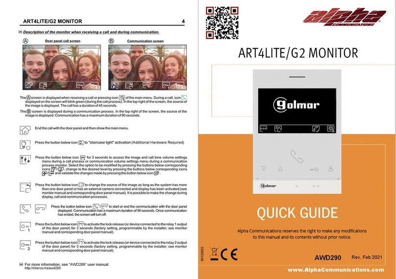
Alpha Communications ART4LITE/G2 User manual

Alpha Communications

Alpha Communications ART4LITE/G2 User manual

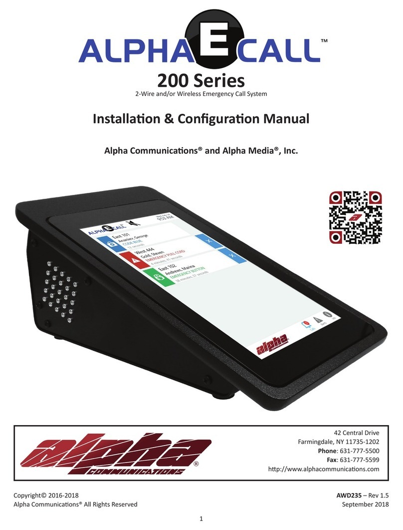
Alpha Communications AlphaECall 200 Series Instruction sheet

Alpha Communications

Alpha Communications AlphaECall 200 Series Instruction sheet

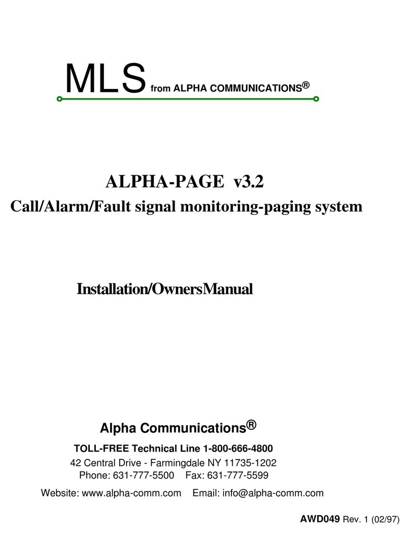
Alpha Communications MLS Operating instructions

Alpha Communications

Alpha Communications MLS Operating instructions

Alpha Communications VH30AK Operating and maintenance manual

Alpha Communications

Alpha Communications VH30AK Operating and maintenance manual

Alpha Communications TekTone Tek-ENTRY User manual

Alpha Communications

Alpha Communications TekTone Tek-ENTRY User manual

Alpha Communications STR QwikBus TT33-2 Assembly instructions

Alpha Communications

Alpha Communications STR QwikBus TT33-2 Assembly instructions

Alpha Communications ALPHA-PAGE v4.0 Operating instructions

Alpha Communications

Alpha Communications ALPHA-PAGE v4.0 Operating instructions

Alpha Communications ART4LITE/G2 User manual

Alpha Communications

Alpha Communications ART4LITE/G2 User manual

Alpha Communications TekTone Tek-View VM104 User manual

Alpha Communications

Alpha Communications TekTone Tek-View VM104 User manual

Alpha Communications VM25WH Series Operating and maintenance manual

Alpha Communications

Alpha Communications VM25WH Series Operating and maintenance manual

Alpha Communications AlphaTouch Instruction sheet

Alpha Communications

Alpha Communications AlphaTouch Instruction sheet

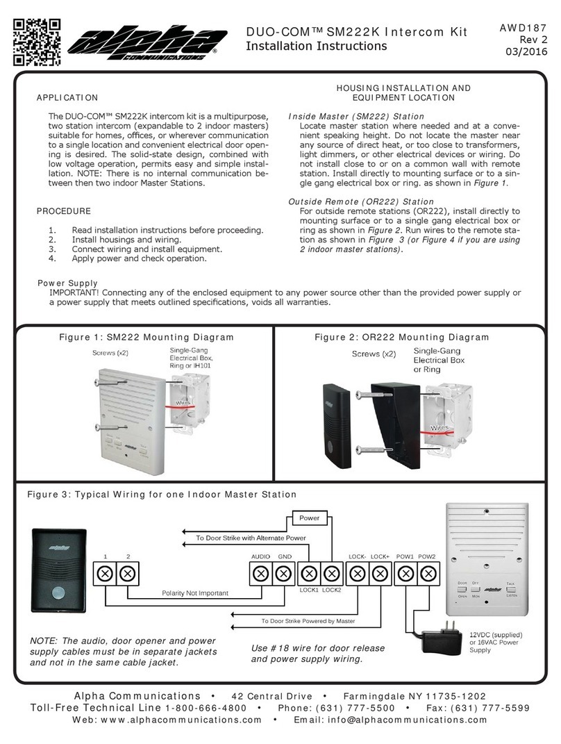
Alpha Communications DUO-COM SM222K User manual

Alpha Communications

Alpha Communications DUO-COM SM222K User manual

Popular Intercom System manuals by other brands

Commax CMV-43A user manual

Commax

Commax CMV-43A user manual

Vimar ELVOX 7548 instruction sheet

Vimar

Vimar ELVOX 7548 instruction sheet

SSS Siedle DCI 600-0 manual

SSS Siedle

SSS Siedle DCI 600-0 manual

urmet domus 1722 COMPLETE USER AND INSTALLER MANUAL

urmet domus

urmet domus 1722 COMPLETE USER AND INSTALLER MANUAL

Steren CCTV-050 quick start guide

Steren

Steren CCTV-050 quick start guide

Bell System bellfree BF user guide

Bell System

Bell System bellfree BF user guide

Cusam Coding Intercom user manual

Cusam

Cusam Coding Intercom user manual

SSS Siedle Siedle Steel SBTLM 651-0 Product information

SSS Siedle

SSS Siedle Siedle Steel SBTLM 651-0 Product information

Tynetec Touch 2 instructions

Tynetec

Tynetec Touch 2 instructions

RTS Two-Wire Intercom RM-325 User instructions

RTS

RTS Two-Wire Intercom RM-325 User instructions

RTS BP-325 user manual

RTS

RTS BP-325 user manual

AMX MET-ECOM-DNS-B installation guide

AMX

AMX MET-ECOM-DNS-B installation guide

BARIX annuncicom 100 Quick install guide

BARIX

BARIX annuncicom 100 Quick install guide

KOCOM KC-C60 manual

KOCOM

KOCOM KC-C60 manual

Fermax DUOX VIDEO MARINE KIT 1-2 L quick start guide

Fermax

Fermax DUOX VIDEO MARINE KIT 1-2 L quick start guide

FARFISA INTERCOMS CD4130MAS manual

FARFISA INTERCOMS

FARFISA INTERCOMS CD4130MAS manual

urmet domus VOG 1760 Booklet

urmet domus

urmet domus VOG 1760 Booklet

Commax DRC-nAC2 user manual

Commax

Commax DRC-nAC2 user manual

manuals.online logo
manuals.online logoBrands
  • About & Mission
  • Contact us
  • Privacy Policy
  • Terms and Conditions

Copyright 2025 Manuals.Online. All Rights Reserved.