manuals.online logo
Brands
  1. Home
  2. •
  3. Brands
  4. •
  5. Alpha Communications
  6. •
  7. Intercom System
  8. •
  9. Alpha Communications NH209TT Series Operating and maintenance manual

Alpha Communications NH209TT Series Operating and maintenance manual

Copyright© 1995-2006, Alpha Communications®, All Rights Reserved. AWD019 Rev. 5 (08/2006)
APPLICATION
The NH209TT series intercom system allows one or more
HT3009 and/or HT2009 series inside handset stations to
communicate with a maximum of one door entry station,
and to release the door opener at the door entry station. A
number of optional accessories are available to provide a
complete entry intercom signaling and communications
system.
PROCEDURE
1. Read installation instructions for each unit to determine
equipment location and installation method.
2. Install housings and wiring.
3. Install equipment.
4. Check wiring and connect. Observe all local and
national electrical and building codes.
5. Apply power and check operation.
HOUSING INSTALLATION AND
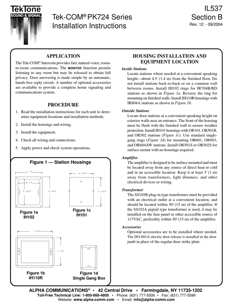
EQUIPMENT LOCATION
INSIDE HANDSET STATIONS
Locatestationswhereneededatconvenientspeakingheight,
about 4.5 feet (137cm) from the finished floor. Handset
can be secured directly to the finished wall surface or can
be mounted over a single gang electrical 'gem' box or single
gang electrical plaster ring.
OUTSIDE STATION
Locate door station at convenient speaking height on
exterior wall near entrance.
NH209TT AMPLIFIER/POWER SUPPLY
The NH209TT amplifier mounts directly behind the speaker/
microphone at the door entry station. It must be located
away from any source of direct heat or extreme cold and
in an accessible location. Keep at least 3 feet (1 meter) away
from transformers, light dimmers or other electrical de-
vices or wiring or sources of electrical interference.
TRANSFORMER
The T1240 plug-in type transformer may be plugged into a
standard 117VAC outlet, preferably within 50' (15 meters)
of the amplifier, but no closer than 3 feet (1 meter) from the
NH209TT amplifier.
NH209TT Amplifier and Power Supply
Installation and Use Instructions Used
with the HT3009 and/or HT2009 Series
Inside Handset Intercom Stations
MULTI ENTRY ADAPTOR
The NH209TT system can only be used with one (1) door
entry station, and cannot be used for multiple door applica-
tions. Therefore, there is no multi entry adaptor available.
The DO-001 (or equivalent 12VAC type) electric door
release is installed in the door jamb in place of the regular
door strike plate.
WIRING
INSIDE HANDSET STATIONS
Run 1 conductor (common) and 1-conductor (selective)
#22AWG cable from station to station and to the NH209TT
amplifier. Additional cables may be used to serve other
stations on other risers (lines). Cables may be straight or
twisted pair type and may be solid or stranded conductors.
Route cable away from AC power wiring, transformers,
fluorescent lights, light dimmers or other electrical devices.
Protect cable from damage. Shielded cable should be used
if AC interference is a concern, or if cables cannot be run
adequately spaced away from any source of electrical
interference.
DOOR ENTRY STATION (using NH209TT)
The NH209TT amplifier/power supply is designed to be
mounted behind the speaker/microphone grille on the door
entry station. Run 2 conductor #18AWG from the 12VAC
transformer to the NH209TT amplifier/power supply. If
distance is greater than 50 feet, use #16AWG cable. Cable
should be run separately from any intercom or #22AWG
wiring. Transformer cable should be a separate jacketed
cable. Protect cable from damage.
DOOR RELEASE
Run 2 conductor #18AWG from the electric door release
location to the NH209TT amplifier. If distance is greater
than 50 feet, use #16AWG cable. Use a separate cable from
the intercom cable, and route away from any intercom
wiring.
CONNECTIONS
Before connecting, make certain wires are free from shorts
or grounds. Make connections as shown on page 4 and as
detailed in the following instructions.
2
that no wires were 'pinched' when handset covers were
affixed.
2. Check each unit in the system for operation in accor-
dance with the operating instructions.
3. If feedback occurs between stations, reduce volume.
Amplifier volume control is preset at the factory, but
may be readjusted, if necessary.
NOTE: The Alpha Communications® warranty is
void if this system is installed or used in any manner
other than described in this manual.
OPERATING INSTRUCTIONS
OUTSIDE DOOR STATION
TO CALL HANDSET: Push button on outside door
station to signal inside handset. An electric buzzer will be
heard at the inside handset station. If the electric buzzer has
been replaced by the optional model R2007 AlphaTone™
unit, an electronic chime warble sound will be heard at the
handset station.
INSIDE HANDSET STATIONS
TO REPLY: Lift the inside handset off of its cradle and
speak in a normal voice. Conversation is full duplex type
(simultaneous talk and listen). If satisfied with the identity of
the caller, you may depress the 'Key Symbol' push-button to
electrically open the entrance door (if so equipped). An AC
type door opener will 'buzz' while operating, indicating
permission to enter. When conversation is completed, hang-
up handset on its cradle.
TROUBLESHOOTING
If the system fails to operate as required, review operating
instructions again. If the equipment fails to operate as
indicated in the instructions, check the following points:
1. ENTIRE SYSTEM DEAD: Check 12VAC at transformer
secondary; wiring between transformer and NH209TT
amplifier; connections at amplifier terminals and for 117
VAC at transformer primary.
2. NO CALL UP BUZZER AT HANDSET: Check for
approx. 12VDC across the two (2) wire leads on the AC
buzzer (or R2007) inside handset, when entry station
pushbutton is depressed. Temporarily switch handset
with one from a functioning location. Check wiring
connections at remote handset. Check that wiring inside
handset base is not restricting movement of buzzer
clapper; temporarily switch handset to another location
that is functioning, and try again. Check that entry station
pushbutton is making contact, by shorting out the two (2)
wires on the back of the button. Check to make sure the
INSIDE HANDSET STATIONS
1. Connect terminal 'I' on handset stations to terminal 'I' on
other handset stations and to terminal '6' on the NH209TT
amplifier/power supply.
2. Connect terminal 'II' on each individual handset station to
the DZ209 Diode Board(s) located in the door entry
station, corresponding to the push-button at the entry door
station, that is used to signal that handset station.
3. Terminals 'Z' and 'K' on each handset station are optional
terminals, and are only used if the 'Red Dot' push-button
needs to be used to operate an optional function.
DOOR ENTRY STATION
1. Connect door entry speaker to terminals '11' and '12' on
the NH209TT amplifier (polarity not important).
2. Connect door entry microphone terminals 'B' and 'U' to
terminals '9' and '10' on the NH209TT amplifier (observe
polarity).
NOTE: The NH209TT amplifier comes factory-wired
with the 9,10,11 and 12 speaker/microphone connections
already installed onto the amplifier.
TRANSFORMER
1. Connect transformer 12VAC terminals to the 12VAC
input terminals ('1' and '2') on the NH209TT amplifier/
power supply. Do not use this transformer to power any
other device, not included on this system.
2. Do not plug the T1240 (plug-in type) transformer into
electrical outlet or connect to 117 VAC until entire
installation is complete and checked.
DOOR OPENER
1. Connect wires coming from door opener to amplifier
terminals '3' and '4'.
NOTE: use proper gauge wiring to door opener.
NOTE: POLARITY OF AC TYPE DOOR OPENER
TERMINALS IS NOT CRITICAL.
DZ209 DIODE BOARD(s)
1. Connect wires coming from terminal '8' on all diode
boards together and then to terminal '8' on the NH209TT
amplifier.
FINISH INSTALLATION
1. Install stations on housings. Do not overtighten screws.
2. Install amplifier and accessory devices as needed.
3. Plug T1240 transformer into 117 VAC outlet. Observe all
local and national electrical and building codes.
TEST AND CHECKOUT
1. At all inside handset stations, make sure the handsets are
hung-up and seated properly on the cradle switch, and
3
DZ209 diode board(s) behind the door entry station are
connected properly. The 'HT' side of the DZ209 should
connect to the selective 'II' terminals from the remote
handsets. The 'T' side of the DZ209 should connect to the
selective terminals from the door entry station push
buttons. Make sure diodes on the DZ209 all have the
striped sides facing the correct way and they are all facing
the same way.
3. NO VOICE ON SYSTEM: Check volume control (poten-
tiometers) on NH209TT amplifier (in both directions; up
and down). Check terminals to handsets. Check speaker/
microphone connections at each entry door station. Con-
nect a single handset at the NH209TT for testing. If voice
is working, amplifier and entry speaker/microphone are
O.K., so check riser wiring. If not, amplifier or speaker/
microphone could be faulty. Check by replacement.
4. UNABLE TO RELEASE DOOR STRIKE: Check wiring
to handset terminals 'I' and 'II'. Temporarily remove both
door opener wires going to amplifier terminals '3' and '4'
and touch to terminals '1' and '2' on amplifier. Check
operating voltage of door opener matches output from
system amplifier. Check wiring (and gauge) to door
opener, from amplifier/power supply. When using a
magnetic type lock or other 'fail-safe' type door lock, you
should use a reversing relay, such as our model# PK407A
for each entrance.
5. HUM OR BUZZ: Check system wiring installed too close
to power wiring or electrical devices or transformers;
check transformer(s) installed too close to control equip-
ment (should be at least three (3) feet away). Wiring is
being run next to wiring for other systems and/or devices.
6. SQUEALING OR HOWLING: Check amplifier volume
control(s) set too high; check for loose speaker/micro-
phone at door entry station.
7. UNABLE TO TALK TO DOOR STATION: Check
terminals 'I' and 'II' going from handsets to amplifier and
DZ209 diode boards for continuity and shorts, grounds,
etc. Check for proper functioning of door entry station
speaker. Check for approx. 16 ohms between terminal '11'
and '12' on speaker microphone (with system wiring
disconnected).
8. UNABLE TO LISTEN TO DOOR STATION: Check
terminals 'I' and 'II' going from handsets to amplifier for
continuity and shorts, grounds, etc. Check for proper
functioning of door entry station microphone.
If these checkpoints fail to indicate the problem,
there may be an equipment fault. Contact the factory
or qualified service representative.
INSTALLING THE R2007 AlphaTone™: When you
wish to replace the standard AC buzzer in the HT3009 series
handsets with the optional model R2007 AlphaTone™ unit,
please follow these instructions: (for HT2009 series hand-
sets see wiring diagram# AWD077).
1. Locate the silver AC buzzer in the lower left portion of the
handset base. Remove the set screw (and keep it for re-
use).
2. Gently pull up the two (2) wires from the buzzer that are
attached to the internal p.c. board. Carefully slide the wires
off of the connecting posts.
3. Install the R2007 AlphaTone™ in place of the buzzer,
using the buzzer set-screw.
4. Install the two (2) wires onto the p.c. board, using the
same connecting posts that the buzzer used. Polarity
does matter. If the R2007 unit fails to signal when called
from the door entry push button, reverse the two (2) wire
leads and try again.
5. Position the wires inside the handset base, so they will not
get 'pinched' when the cover is placed over the base.
6. Using a small screwdriver, you can change the AlphaTone's
sound, by adjusting the built-in potentiometer found on the
p.c. board of the R2007.
4
TYPICAL WIRING LAYOUT DIAGRAM
FOR A SINGLE ENTRANCE SYSTEM
Notes:
1. Use #18AWG wiring to transformer and door opener. All other wiring can be #22AWG.
2. Talk down volume can be adjusted using volume control (potentiometer) on NH209TT amplifier/power supply.
3. When connecting to a magnetic door lock or other 'fail safe' type door lock, use the optional model PK407A
specialty relay, for each entrance door lock.
4. If the NH209TT amplifier is not mounted behind the entry door station, and is mounted remotely, we recommend
using shielded cable from the speaker/microphone wires to the NH209TT amplifier/power supply.
5. Transformer and door opener wiring MUST NOT be in same cable as handset wiring!!!
6. Observe all local and national electrical codes.
ALPHA COMMUNICATIONS® • 42 Central Drive • Farmingdale NY 11735-1202
TOLL-FREE TECHNICAL LINE 1-800-666-4800 • Phone: 631-777-5500 • Fax: 631-777-5599
WEBSITE: www.AlphaCommunications.com • EMAIL: [email protected]

This manual suits for next models

2

Other Alpha Communications Intercom System manuals

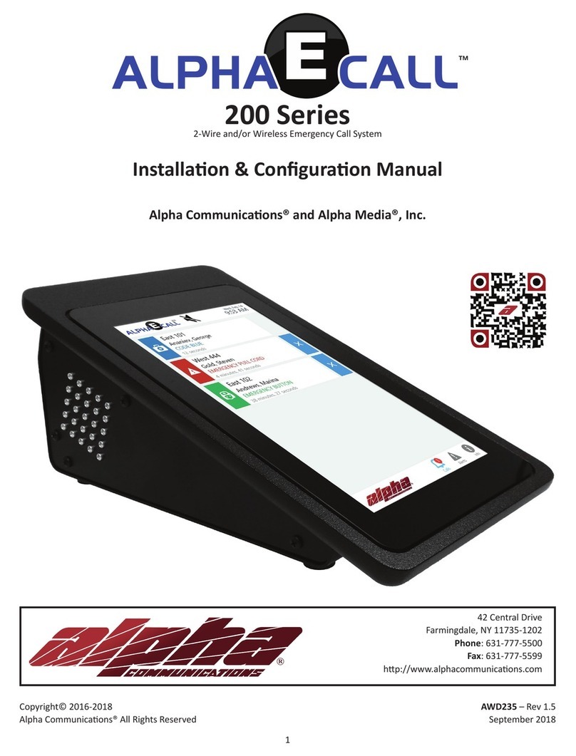
Alpha Communications ART4LITE/G2 User manual

Alpha Communications

Alpha Communications ART4LITE/G2 User manual

Alpha Communications AlphaTouch Instruction sheet

Alpha Communications

Alpha Communications AlphaTouch Instruction sheet

Alpha Communications ALPHA-PAGE v4.0 Operating instructions

Alpha Communications

Alpha Communications ALPHA-PAGE v4.0 Operating instructions

Alpha Communications VM25WH Series Operating and maintenance manual

Alpha Communications

Alpha Communications VM25WH Series Operating and maintenance manual

Alpha Communications TekTone Tek-View VM104 User manual

Alpha Communications

Alpha Communications TekTone Tek-View VM104 User manual

Alpha Communications STR QwikBus TT33-2 Assembly instructions

Alpha Communications

Alpha Communications STR QwikBus TT33-2 Assembly instructions

Alpha Communications ART4LITE/G2 User manual

Alpha Communications

Alpha Communications ART4LITE/G2 User manual

Alpha Communications TekTone Tek-COM PK724 Series User manual

Alpha Communications

Alpha Communications TekTone Tek-COM PK724 Series User manual

Alpha Communications TekTone Tek-ENTRY User manual

Alpha Communications

Alpha Communications TekTone Tek-ENTRY User manual

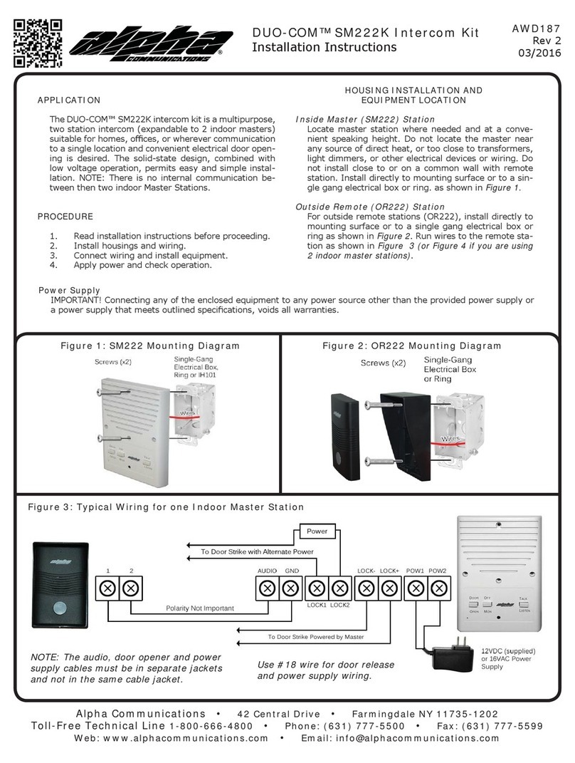
Alpha Communications DUO-COM SM222K User manual

Alpha Communications

Alpha Communications DUO-COM SM222K User manual

Alpha Communications VPD-5000 User manual

Alpha Communications

Alpha Communications VPD-5000 User manual

Alpha Communications STR QwikBus Assembly instructions

Alpha Communications

Alpha Communications STR QwikBus Assembly instructions

Alpha Communications Duo Com DC-300 Instruction sheet

Alpha Communications

Alpha Communications Duo Com DC-300 Instruction sheet

Alpha Communications VMH25WH Series Operating and maintenance manual

Alpha Communications

Alpha Communications VMH25WH Series Operating and maintenance manual

Alpha Communications VH30AK Operating and maintenance manual

Alpha Communications

Alpha Communications VH30AK Operating and maintenance manual

Alpha Communications MLS Operating instructions

Alpha Communications

Alpha Communications MLS Operating instructions

Alpha Communications AlphaECall 200 Series Instruction sheet

Alpha Communications

Alpha Communications AlphaECall 200 Series Instruction sheet

Popular Intercom System manuals by other brands

FARFISA INTERCOMS EH9161FPLCW quick start guide

FARFISA INTERCOMS

FARFISA INTERCOMS EH9161FPLCW quick start guide

Viking HID-1 Technical practice

Viking

Viking HID-1 Technical practice

ACO FAM-PV Series User instruction

ACO

ACO FAM-PV Series User instruction

E-data AR402 manual

E-data

E-data AR402 manual

Mircom TX3 Series installation manual

Mircom

Mircom TX3 Series installation manual

urmet domus 1083 System Booklet

urmet domus

urmet domus 1083 System Booklet

Aiphone IE-2AD(U instructions

Aiphone

Aiphone IE-2AD(U instructions

Tokyo Gas IBR-A08A-BGISV operating manual

Tokyo Gas

Tokyo Gas IBR-A08A-BGISV operating manual

Transmitter Solutions EIS-2 user manual

Transmitter Solutions

Transmitter Solutions EIS-2 user manual

Vimar ELVOX 885G/S Installer's guide

Vimar

Vimar ELVOX 885G/S Installer's guide

Extel MEMO 2 Installation and user guide

Extel

Extel MEMO 2 Installation and user guide

Elvox 40510 instruction manual

Elvox

Elvox 40510 instruction manual

2N IP Solo installation manual

2N

2N IP Solo installation manual

Aiphone JM-DVF-L installation manual

Aiphone

Aiphone JM-DVF-L installation manual

DoorBird D1101KH installation manual

DoorBird

DoorBird D1101KH installation manual

auer IC3P operating manual

auer

auer IC3P operating manual

ABB Welcome IP H81381P Series product manual

ABB

ABB Welcome IP H81381P Series product manual

David Clark 9500 SERIES installation manual

David Clark

David Clark 9500 SERIES installation manual

manuals.online logo
manuals.online logoBrands
  • About & Mission
  • Contact us
  • Privacy Policy
  • Terms and Conditions

Copyright 2025 Manuals.Online. All Rights Reserved.