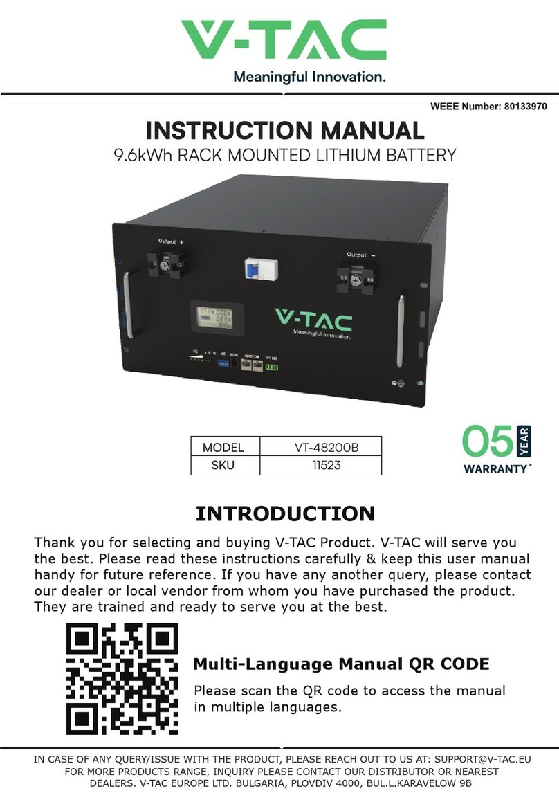
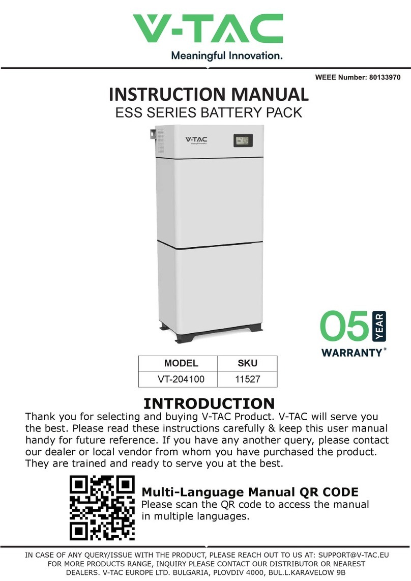
V-TAC VT-48280-W2 User manual

INSTRUCTION MANUAL
INTRODUCTION
14.33kWh WALL MOUNTED LITHIUM BATTERY
WEEE Number: 80133970
IN CASE OF ANY QUERY/ISSUE WITH THE PRODUCT, PLEASE REACH OUT TO US AT: SUPPORT@V-TAC.EU
FOR MORE PRODUCTS RANGE, INQUIRY PLEASE CONTACT OUR DISTRIBUTOR OR NEAREST DEALERS.
V-TAC EUROPE LTD. BULGARIA, PLOVDIV 4000, BUL.L.KARAVELOW 9B
Thank you for selecting and buying V-TAC Product. V-TAC will serve youthe
best. Please read these instructions carefully & keep this user manualhandy for
future reference. If you have any another query, please contact our dealer or
local vendor from whom you have purchased the product. They are trained and
ready to serve you at the best.
VT-48280-W2 11525
MODEL SKU
MULTI-LANGUAGE MANUAL QR CODE
Please scan the QR code to access the manual in
multiple languages.

About This Document
Purpose
This document primarily introduces the main features, component composion, usage, installaon, and
maintenance of Wall-mounted Residenal Energy Storage System VE51280W (short for V-Power S14).
Intended Audience
This document is intended for:
Hardware installaon engineers
Technical support engineers
Maintenance engineers
Users
Symbol Convenons
The symbols that may be found in this document are dened as follows.
Symbol Denion Remarks
Danger Indicates a hazard with a high level of risk which, if not avoided, will
result in death or serious injury.
Warning Indicates a hazard with a medium level of risk which, if not avoided,
could result in death or serious injury.
Aenon Indicates a hazard with a low level of risk which, if not avoided,
could result in minor or moderate injury.
Note
Supplements the important informaon in the main text.
NOTE is used to address informaon not related to personal injury,
equipment damage, and environmental deterioraon.
Change History
Changes between the issued documents are cumulave. The latest document issued contains all the
changes madein earlier versions.
Issue 01 (2023-01-31)
This issue is the rst oal release.
1

Contents
About This Document ..................................................................................................................1
1 Introducon ..........................................................................................................................3
1.1 Applicaon ........................................................................................................................................... 3
1.2 Appearance .......................................................................................................................................... 3
1.3 Panel Introducon................................................................................................................................ 4
1.4 PIN Denion ....................................................................................................................................... 6
1.5 Lithium-ion Cell .................................................................................................................................... 7
1.6 Technical speccaons ........................................................................................................................ 8
2Installaon ..........................................................................................................................10
2.1 Precauons for Installaon ................................................................................................................ 10
2.2 Preparing for Installaon.................................................................................................................... 10
2.2.1 Tools ............................................................................................................................................................... 10
2.2.2 Packing List..................................................................................................................................................... 11
2.2.3 Unpacking Acceptance................................................................................................................................... 12
2.3 Installing Guide................................................................................................................................... 12
2.4 Connecng Power Cable .................................................................................................................... 13
2.5 Connecng Communicaon Cable ..................................................................................................... 16
3Operaon............................................................................................................................18
3.1 Check before Power-on...................................................................................................................... 18
3.2 Power-on ............................................................................................................................................ 18
3.3 Operaon Guide................................................................................................................................. 19
4 Maintenance .......................................................................................................................21
4.1 V-Power S14 Storage .......................................................................................................................... 21
4.2 Monthly Maintenance........................................................................................................................ 21
4.3 Quarterly Maintenance ...................................................................................................................... 22
4.4 Yearly Maintenance............................................................................................................................ 22
4.5 Alarm Handling................................................................................................................................... 22
Acronyms and Abbreviaons......................................................................................................24
2

Figure 1. VT-48280-W2 Appearance
VT-48280-W2
VT-48280-W2
VT-48280-W2
VT-48280-W2

Figure 3. VT-48280-W2 Operation Panel
Figure 2. VT-48280-W2 Dimensions (Unit:mm)
VT-48280-W2

The definition of the VT-48280-W2 operation panel is shown as follows.
VT-48280-W2
VT-48280-W2

VT-48280-W2
VT-48280-W2

1.5 Lithium-ion Cell
The lithium iron phosphate cell selected in the scheme is a special energy-type lithium baery product.
This series of lithium iron phosphate cells have high speci energy, longer cyclelife, low cost, capable of
high current charge and discharge, high-temperature tolerance, high energy density, safety, and polluon-
free features.
Lithium-ion cell's three views are shown as follows.
Figure 4. Lithium-ion cell three views (unit: mm)
Lithium-ion cell main technical specicaons are shown as follows.
Table 5. Lithium-ion cell main technical specicaons
No. Items Parameter
1 Baery type LiFePO
2 Rated voltage 3.2 V
3 Rated capacity 280 Ah
4 Rated energy 0.896 kWh
5 Max connuous charge current 200 A
6 Max connuous discharge current 200 A
7 Charging cut-ovoltage 3.65V
7

VT-48280-W2
VT-48280-W2

No. Items Parameter
13 Storage temperature 0~ 45
14 Operang temperature Discharge -20 ~ 55°C, Charge 0°C ~50
15 SOC esmaon value <8%
16 Allowable relave humidity 5% ~ 95% Non-condensing
17 Altude 2000m without derang
18 Cooling method Natural heat dissipaon
19 Protecon level IP65
20 External Interface
Baery posive and negave quick plug terminals:
2*P+, 2*P-
Communicaon standard RJ45 port:2*RJ45
21 Installaon method Floor
22 Display method Indicator light (power, operaon status)
23 Size (Width*High*Depth) 505.0 mm×801.5 mm×251.0 mm (without base)
24 Net weight Approx. 121 kg
Protection function
25 Over-voltage protecon System over-voltage, cell over-voltage
26 Under-voltage protecon System under-voltage, cell under-voltage
27 Over-current protecon Charging over-current, discharging over-current
28 Temperature protecon
Charging high temperature, charging low temperature,
discharging high temperature, discharging low
temperature
29 Short circuit protecon BMS hardware protecon, external fuse
30 Reverse connecon protecon Available, when it is powered o
31 Dielectric withstand test Available
32 Pre-charge funcon Available
33 Equalizaon funcon Available
34 Hibernaon funcon Available
9

2Installaon
2.1 Precauons for Installaon
Light intensity is required near the installaon locaon.
Comply with the safety operaon technical regulaons when liing and handling heavy objects.
Equipment and tools must be complete, intact, and reliable. It is strictly prohibited to use tools with
cracks, burrs, loose handles, etc., that do not meet the safety standards.
Installaon operaons must be guided by qualied engineers.
Duringinstallaon, two people must work together, one operag and the other inspecg.
The original cable connecon and operaon process shall not change without the authorizaon of
the company's consent.
2.2 Preparing for Installaon
2.2.1 Tools
Insulated installaon tools must be used to prevent electric shocks. If tools without insulaon protecon
are used, the exposed metal parts must be wrapped and insulated with insulag tape.
The following table shows tools that need to be prepared before installaon.
Table 7. Tools
Electric screwdriver Manual forkliElectric forkliImpact drill
Levelling instrument Socket wrench Phillips screwdriver Insulated torque wrench
10

VT-48280-W2

VT-48280-W2
VT-48280-W2
VT-48280-W2
VT-48280-W2
VT-48280-W2
VT-48280-W2

VT-48280-W2
VT-48280-W2 VT-48280-W2

Context
1 Insulate installaon tools to prevent electric shocks.
2According to the power value of the inverter, the power cable should be connected. If mulple beries are used in
parallel, the power cables should be connected according to the wiring mode in Figure 9.
The VT-48280-W2 power cable connecon method adopts a self- locking connector. The descripon of
the self-locking connector is shown as follows:
The steps for connecg the self-locking connector are as follows:
A Adjust the direcon of the self-locking connector to align with the VT-48280-W2 terminal.
B Rotate the self-locking connector slightly, and it will be inserted automacally.
C Aer the self-locking connector is automacallyinserted, push it in slightly, and aer hearing a
click sound, the self-locking connector and the baery module terminal are connected.
Need to press the buons on the self-locking connector simultaneously when users need to pull
out the self-locking connector.
Figure 8. Self-locking connector buon
If there are muleVT-48280-W2 in parallel, you need to connect them in parallel using the parallel power
cables, then connect the power cable to the inverter. Please pay aenon to the dison between
baery modules’ posive and negave terminals.
Procedure
1Connect the internal power cables of VT-48280-W2
14

Figure 9. Connect the internal cables
2Connect the P+ & P- power cables to the inverter.
Figure 10. Connect the external cables
The self-locking connector's color should correspond to the VT-48280-W2 terminal's color: orange corresponds to
the posive pole, and black corresponds to the negave pole.
Please take care of the removed VT-48280-W2 protecve cover in case of backup.
15

2.5 Connecng Communicaon Cable
Context
Please pay enon to the direcon when plugging the communicaon cable connector, do not operate violently.
Communicaon cables and power cables must be routed separately.
If there are muleVT-48280-W2 in parallel, you need to connect the communicaon cables in parallel
rst. Then you need to connect the communicaon cable of the inverter to COM1 of any VT-48280-W2
Procedure
1Connect the internal communicaon cables of the VT-48280-W2
Figure 11. Connect the internal cables
2Connect the remaining power cables and communicaon cables between the VT-48280-W2 and
inverter.
Figure 12. Connect the external cables
16

3For the wiringdiagram of the inverter to the user side, please refer to the user manual of inverter.
Please conrm the usage scenarios of the inverter according to the actual situaon. For details, please refer to the
user manual of inverter.
The communicaon cable to the inverter contains L&N cable (220V power supply for BMS). Please connect this cable
to the output port of the inverter. (Oponal)
Recommended open-circuit current from the bery to the inverter: rated operang current 250A, rated operang
voltage DC110V, rated short circuit breaking capacity 25kA (DC110V). If the inverter has instrucons, the inverter
shall prevail.
17

VT-48280-W2
VT-48280-W2
VT-48280-W2
VT-48280-W2

VT-48280-W2
This manual suits for next models
1
Table of contents
Other V-TAC Batteries Pack manuals
Popular Batteries Pack manuals by other brands

Makita
Makita BL36120A Original instruction manual

Aeson Power
Aeson Power TL-LFP Series Installation and operation manual

Hubbell
Hubbell DualLite PLD12MI installation instructions

Optika
Optika M-069 instruction manual

Black & Decker
Black & Decker LB018OPE instruction manual

ULTIMATRON FRANCE
ULTIMATRON FRANCE SMART BMS Series Instructions for use