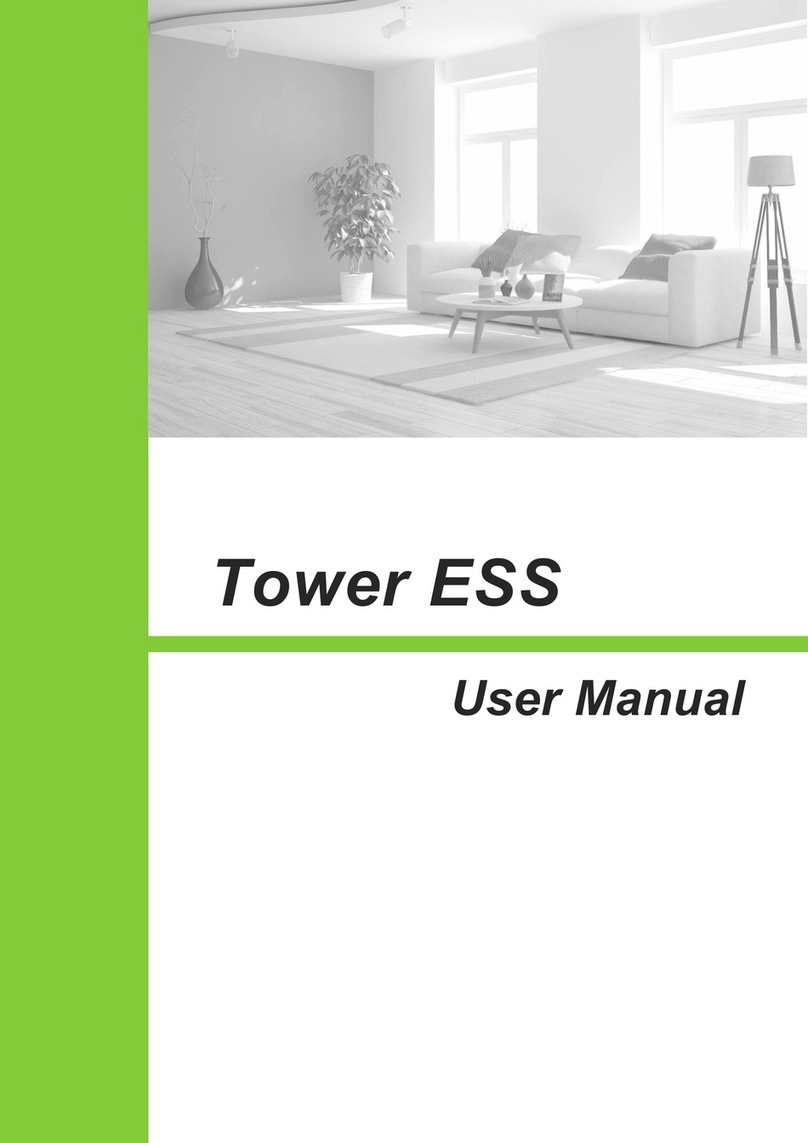
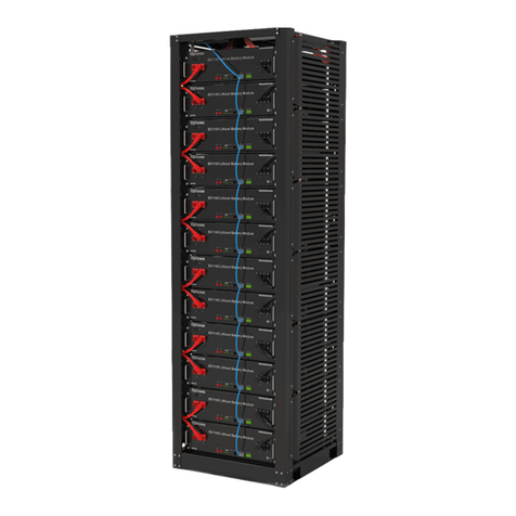
Dyness TowerESS User manual

User Manual
Tower ESS
www.plentisolar.de

Tower ESS Unit User Manual
I
Content
Statement of Law..........................................................................................................
1
Safety handling of lithium batteries Guide..................................................................
2
1 Introduction.............................................................................................................
4
1.1 Brief Introduction.........................................................................................................4
1.2 Product Properties....................................................................................................... 4
1.3 Product identity definition...........................................................................................4
2 Product Specification..............................................................................................
6
2.1 System Performance Parameter ................................................................................6
2.2 Battery Module............................................................................................................ 8
2.3 Battery Controller...................................................................................................... 12
3 Installation and Configuration.............................................................................
15
3.1 Environmental Requirement ................................................................................... 15
3.2 Installation clearance requirements......................................................................... 15
3.3 Installation location precautions...............................................................................16
3.4 Tools........................................................................................................................... 17
3.5 Safety Gear.................................................................................................................... 17
3.6 Unpacking inspection.................................................................................................17
3.7 Equipment installation...............................................................................................19
4 Maintenance.........................................................................................................
25
4.1 Trouble Shooting:..........................................................................................................25
4.2 Replacement of main component.............................................................................26
4.3 Battery Maintenance.................................................................................................... 26
5 Storage Recommendations......................................................................................
27
6 Shipment...................................................................................................................
27
Tower ESS Unit User Manual
1
Statement of Law
Copyright of this document belongs to Daqin New Energy Tech (Taizhou) Co., Ltd.
No part of this documentation maybe excerpted, reproduced, translated,
annotated or duplicated in any form or by any means without the prior
written authorization of Daqin New Energy Tech (Taizhou) Co., Ltd. All Rights Reserved.
This product complies with the design requirements of environmental protection and personal
safety. The storage, use and disposal of the products shall be carried out in accordance with the
product manual, relevant contract or relevant laws and regulations.
Customer can check the related information on the website of Jiangsu Daqin New Energy Tech
(Taizhou) Co., Ltd. when the product or technology is updated.
Web URL:http://www.dyness-tech.com.cn/
Please note that the product can be modified without prior notification.
Revision History
Revision NO.
Revision Date
Revision Reason
1.0
2019.09.11
First Published
2.0
2020.03.03
Structural design changed
3.0
2020.06.28
Parameter changes
3.1
2020.09.28
1.Change the connector of the power cable
2.Change the color of Power wake button
3. Add a negative output point and a module
positive point on composite plug of module,
add a negative output point and a module
negative point on composite socket of
module.
4.Add a positive output point and a negative
output point on the composite socket of BDU.
5.Update battery nameplate and module label
3.2
2021.3.2
1、Update the System Performance Parameter
2、Update Installation clearance requirements
3、Update Installation location precautions
4、Update the Grounding.
3.3
2021.3.15
Upgrade adaptive function
产

Tower ESS Unit User Manual
2
Safety handling of lithium batteries Guide
symbol
Danger
●Battery strings will produce high voltage DC
power and can cause a lethal voltage and
electric shock.
●Only qualified person can perform the wiring
of the battery strings.
Warning
Risk of battery system damage or personal injury
●DO NOT pull out the connectors while the
system is operating!
●De-energize from all multiple power sources
and verify that there is no voltage.
Caution
Risk of battery system failure or life cycle
reduction.
Warning: This product is a high voltage DC system, operated by
authorized person only.
Danger: Before installation or operation you must read <Operation
Menu> carefully.
Caution:
Before Connecting
Please check product and packing list first after unpacking, if product is damaged or lack of
parts, please contact with the local retailer;
Before installation, be sure to cut off the grid power and make sure the battery is in the
turned-off mode;
Do not mistake the positive and negative cables and ensure there are no short circuit
connection to the external device;

Tower ESS Unit User Manual
3
It is prohibited to connect the battery to AC power directly;
Battery system must be well grounded and the resistance must be less than 1 Ω
Please ensured the electrical parameters of battery system are compatible to related
equipment;
Keep the battery away from water and fire.
In Using
If the battery system needs to be moved or repaired, the power must be cut off and ensure
the battery is completely shut down;
It is prohibited to connect the battery with different type of battery.
It is prohibited to put the batteries working with faulty or incompatible inverter;
It is prohibited to disassemble the battery (Warranty tab removed or damaged);
In case of fire, only dry powder fire extinguisher can be used, liquid fire extinguishers are
prohibited;
Please do not open, repair or disassemble the battery except staffs from Dyness or
authorized by Dyness. We do not undertake any consequences or related responsibility which
because of violation of safety operation or equipment safety standards.
Caution
Please read the user manual carefully (in the accessories);
If the battery is stored for a long time , it is required to charge them every six months, and
the SOC should be no less than 80%;
Battery needs to be recharged within 12 hours, after fully discharged;
Do not expose cable outside;
All the battery terminals must be disconnected for maintenance;
Please contact the supplier within 24 hours if there is something abnormal.
The warranty claims are excluded for direct or indirect damage due to items above.

Tower ESS Unit User Manual
4
1 Introduction
1.1 Brief Introduction
Tower is a high voltage battery storage system based on lithium iron phosphate battery, and it’s
one of the new energy storage products developed and produced by Dyness. it can be used to
support reliable power for various types of equipments and systems. Tower is especially suitable
for application scene of high power, limited installation space, restricted load-bearing and long
cycle life.
1.2 Product Properties
The whole module is non-toxic, non-polluting and environmentally friendly;
Anode material is made from LiFePO4 with safety performance and long cycle life;
Battery management system (BMS) has protection functions including over-discharge,
over-charge, over-current and high/low temperature;
The system can automatically manage charge and discharge state and balance current and
voltage of each cell;
Flexible configuration, multiple battery modules can be in serial for expanding voltage and
Capacity.
Adopted self-cooling mode rapidly reduced system entire noise;
The module has less self-consumption, up to 6 months without charging; no memory effect,
excellent performance of shallow charge and discharge;
Working temperature range is from 0 to 50 ℃, with excellent discharge performance and
cycle life;
Small size and light weight, standard module is comfortable for installation and
maintenance;
1.3 Product identity definition
Figure 1-1 Battery Energy Storage System nameplate

Tower ESS Unit User Manual
5
Battery voltage is higher than safe voltage, direct contact
with electric shock hazard.
Be careful with your actions and be aware of the dangers.
Read the user manual before using.
The scrapped battery cannot be put into the garbage can
and must be recycled by professional personnel or
institutes.
After the battery life is terminated, the battery can
continue to be used after it recycled by the professional
recycling organization and do not discard it at will.
This battery product meets European directive
requirements.
This battery product passed the TUV certification test.
Figure 1-2 Battery module label

Tower ESS Unit User Manual
6
2 Product Specification
2.1 System Performance Parameter
Table 2-1 The parameter of Tower system
System List
T21
T17
T14
T10
T7
Module Type
LFP
LFP
LFP
LFP
LFP
Total Storing Energy [kWh]
21.31
17.76
14.21
10.66
7.10
Usable Capacity [kWh]
21.31
17.76
14.21
10.66
7.10
Recommend Depth of Discharge
80%
80%
80%
80%
80%
Max Depth of Discharge
100%
100%
100%
100%
100%
Module configuration
6 Series
5 Series
4 Series
3 Series
2 Series
Voltage Range[Vdc]
504~657
420~547
336~438
252~328
168~219
Battery System Voltage (Vdc)
576
480
384
288
192
Battery System Capacity (Ah)
37
37
37
37
37
Battery System Charge Voltage
(Vdc)
657
547.5
438
328.5
219
Battery System Charge Current [A]
(Standard)
7.4
7.4
7.4
7.4
7.4
Battery System Charge Current [A]
(Normal)
18.5
18.5
18.5
18.5
18.5
Battery System Charge Current [A]
(Max)
37
37
37
37
37
Battery System Discharge
lower-Voltage (Vdc)
504
420
336
252
168
Battery System Discharge Current
[A] (Standard)
7.4
7.4
7.4
7.4
7.4
Battery System Discharge Current
[A] (Normal)
18.5
18.5
18.5
18.5
18.5

Tower ESS Unit User Manual
7
Battery System Discharge Current
[A] (Max)
37
37
37
37
37
Battery System Max. Charge&
Discharge Current [A]
(when used in communication with
the inverter)
22.5
22.5
22.5
22.5
22.5
Discharge condition
0℃~50℃
0℃~50℃
0℃~50℃
0℃~50℃
0℃~50℃
Charge condition
0℃~50℃
0℃~50℃
0℃~50℃
0℃~50℃
0℃~50℃
Max. Discharge Power [kW]
21.31
17.76
14.21
10.66
7.1
Max.Charge& Discharge Power [kW]
(when used in communication with
the inverter)
12.78
10.65
8.52
6.39
4.2
Short Circuit Current [kA]
1.5
1.5
1.5
1.5
1.5
Enclosure Protection (IP)
IP54
IP54
IP54
IP54
IP54
Size [mm]
1500
*504*380
1300
*504*380
1100
*504*380
900
*504*380
700
*504*380
Weight [kg]
269
228
187
146
105
Battery Module Name
HV9637
HV9637
HV9637
HV9637
HV9637
Battery Module Quantity(pcs)
6
5
4
3
2
T14

Tower ESS Unit User Manual
8
2.2 Battery Module

Tower ESS Unit User Manual
9
Table 2-2 Product parameters
Module Name
HV9637
Cell Technology
Li-ion(LFP)
Battery Module Capacity (kWh)
3.552
Battery Module Voltage (Vdc)
96
Battery Module Capacity (Ah)
37
Battery Module Cell Quantity (pcs)
30
Battery Cell Capacity (Wh)
118.4
Battery Cell Voltage (Vdc)
3.2
Battery Cell Capacity (Ah)
37
Battery Module Cell Quantity in Series (pcs)
30
Battery Module Charge Voltage (Vdc)
109.5
Battery Module Charge Current (Standard) [A]
7.4
Battery Module Charge Current (Normal) [A]
18.5
Battery Module Charge Current (Max.) [A]
37
Battery Module Discharge lower-Voltage (Vdc)
84
Battery System Discharge Current (Standard) [A]
7.4
Battery Module Charge Current (Normal) [A]
18.5
Battery Module Charge Current (Max.) [A]
37
Dimension(W*D*H, mm)
504*380*240
Communication mode
CAN
Pollution Degree (PD)
II
Ambient Temperature(℃)
0~50
IP Grade
IP54
Weight(kg)
41
HV9637 top interface

Tower ESS Unit User Manual
10
HV9637 bottom interface
Table 2-3 Interface Definition
Item
Name
Definition
1
Composite connector-Plug
Battery module output and communication interface
2
Composite connector-Socket
Battery module output and communication interface
1
2

Tower ESS Unit User Manual
11
Composite connector-Plug composite connector-Socket
Table 2-4 Port Definition
NO
Composite connector-plug
Composite connector-socket
1
Negative output
Negative output
2
Module positive
Module negative
3
SWAKE
SWAKE
4
SCANSG
SCANSG
5
SCANL
SCANL
6
SCANH
SCANH
7
24V-
24V-
8
24V+
24V+
9
SCANIN
SCANOUT
1
4
5
8
7
2
3
6
1
5
8
7
2
4
3
6
1
1
2
2
9
9

Tower ESS Unit User Manual
12
2.3 Battery Controller
BDU right interface
BDU left interface
BDU bottom interface
1
2
6
3
4
5
7

Tower ESS Unit User Manual
13
Table 2-5 Interface Definition
Item
Name
Definition
1
Power Wake
Button
Long press this button to start the battery system
2
External Positive
socket
Connect battery system with Inverter positive terminal
3
EXT-CAN
Communication
Port
RJ45 communication port between the battery system and
inverter
4
External Negative
socket
Connect battery system with Inverter negative terminal
5
Power On switch
Turn on the switch to power the BMS system
6
DC Breaker
The master switch of the battery system,you must switch on it
before switching on power on&power wake switch; Short
circuit protection.
7
Composite
connector-Socket
Battery module output and communication interface
NO
Definition
1
Negative output
2
Positive output
3
SWAKE
4
SCANSG
5
SCANL
6
SCANH
7
24V-
8
24V+
9
SCANOUT
1
4
5
8
7
2
3
6
1
2
9

Tower ESS Unit User Manual
14
Caution: When the DC breaker is tripped off because of over current or short
circuit, must wait after 30min to turn on it again, otherwise may cause the breaker
damage.
Power On Button: Generally when it is at ON state, you can’t turn off it during
normal running condition.
Danger: Ensure Power On Switch is turned on before waking up the battery.
Otherwise it will affect automatic checking process and cause danger.
Danger: DO NOT turn off the “ Power On Switch” during normal running condition,
only in emergency case it could be turned off directly. Otherwise will cause this
battery string current surge by another battery strings.
Definition of “EXT-CAN”port pin
PIN
Color
Definition
PIN1
Orange/White
Reserved
PIN2
Orange
XGND
PIN3
Green/White
Reserved
PIN4
Blue
CANH
PIN5
Blue/White
CANL
PIN6
Green
NC
PIN7
Brown/White
Reserved
PIN8
Brown
NC

Tower ESS Unit User Manual
15
3 Installation and Configuration
3.1 Environmental Requirement
3.1.1 Cleanliness
The battery system has high voltage connectors. The environment condition will affect the
isolation performance of the system.
Before installation and system power on, the dust and iron scurf must be removed to keep a
clean environment. And the environment must have certain anti-dust ability.
Dust and humidity condition shall be periodic checked during the system continuous operation.
3.1.2 Temperature
Tower system working temperature range: 0℃~50℃; Optimum temperature: 18℃~30℃;
Caution: Out of the working temperature range will cause the battery system over / low
temperature alarm or protection which may lead to the cycle life reduction.
3.1.3 Cooling System
It is essential to equip a cooling system to keep the battery system in a relevant temperature
range.
Caution: Out of the working temperature range will cause the battery system over / low
temperature alarm or protection which may lead to the cycle life reduction.
3.1.4 Heating System
It is essential to equip a heating system to keep the battery system in a relevant temperature
range. If the environment is lower than 0 ℃,the system may be shut down for protection
purpose. It is necessary to open the heating system at first.
Caution: Out of the working temperature range will cause the battery system over / low
temperature alarm or protection which may lead to the cycle life reduction.
3.1.5 Fire-extinguisher System
The room must be equipped with fire-extinguisher system for safety purpose. The fire system
needs to be regularly checked to be in normal condition. Refer to the using and maintenance
requirements, please follow local fire equipment guidance.
3.1.6 Grounding System
Make sure the grounding point for battery system is stable and reliable before the battery
installation. If the battery system is installed in an independent equipment cabin(e.g. container),
must make sure the grounding of the cabin is stable and reliable.
The resistance of the grounding system must ≤100mΩ
3.2 Installation clearance requirements
Please note that the battery should be installed with a minimum safe clearance from the
surrounding equipment or battery. Please refer to the minimum clearance diagram below.

Tower ESS Unit User Manual
16
3.3 Installation location precautions

Tower ESS Unit User Manual
17
3.4 Tools
The following tools are required to install the battery pack:
NOTE:
Use properly insulated tools to prevent accidental electric shock or short circuits.
If insulated tools are not available, cover the entire exposed metal surfaces with available
insulated alternatives, except their tip, with electrical tape.
3.5 Safety Gear
It is recommended to wear the following safety gear when dealing with the battery pack
3.6 Unpacking inspection
When the equipment arrives at the installation site, loading and unloading should
be performed according to the rules and regulations, to prevent from being
exposed under sunlight. Battery should not be installed in direct sunlight. Please
refer to Section 3.3
Before unpacking, the total number of packages shall be indicated according to the
shipping list attached to each package, and the case shall be checked for good
condition.
In the process of unpacking, handle with care and protect the surface coating of the
object.
Open the package, the installation personnel should read the technical documents,
verify the list, according to the configuration table and packing list, ensure objects

Tower ESS Unit User Manual
18
are complete and intact, if the internal packing is damaged, should be examined
and recorded in detail.
Packing list is as follows:
Item
Specification
Quantity
Figure
Tower BDU
504*380*156.5mm
1 PCS
Battery Module
HV9637
96V/37Ah
504*380*240mm
4 PCS
Tower Base
504*380*186mm
1 PCS
Communication
cable to inverter
Standard,Black
/L2000mm /RJ45
plug at both sides
1 PCS
Communication
connector to BDU
RJ45 Waterproof
connector
1 PCS
Cross recessed
countersunk
head screw
M4*10
20 PCS
M6 3 sets of
combined screws
M6*14
1 PCS
Ground wire
L500mm,4mm²
1 PCS
This manual suits for next models
1
Table of contents
Other Dyness Batteries Pack manuals

Dyness
Dyness POWERCUBE Series User manual

Dyness
Dyness POWERBOX Pro User manual

Dyness
Dyness A48100 User manual

Dyness
Dyness DL5.0C User manual

Dyness
Dyness B3 User manual

Dyness
Dyness B4850 User manual

Dyness
Dyness Junior Box User manual

Dyness
Dyness B48100 User manual

Dyness
Dyness PowerDepot H5B User manual

Dyness
Dyness PowerRack HV4 User manual