1.3 Working Principle and Function
ŸParallel connection: Support the parallel connection of one to six Battery Modules.
ŸReport: Report alarms and status data to the hybrid inverter.
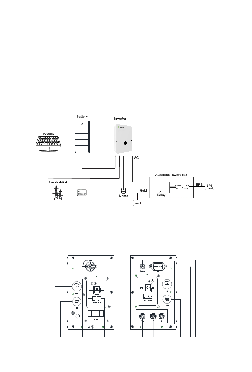
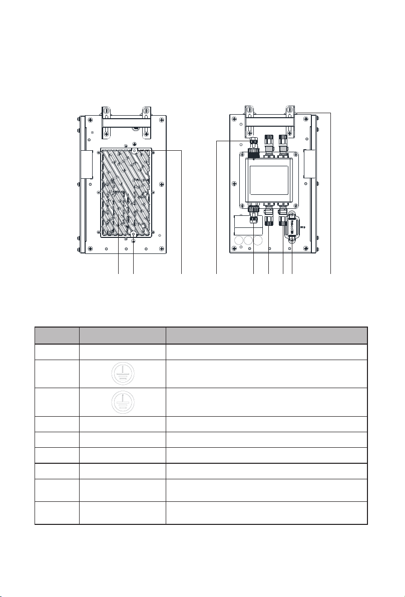
The APX 5.0-30.0P-S0-US high voltage battery system is composed of a Power Module
APX 55042-P0-US and multiple Battery Modules APX 5.0P-B1-US connected in parallel. It
contains electrochemical batteries, battery control units, power control units, battery
management units, power and signal terminals, and mechanical parts.
A single APX system can connect 1 to 6 Battery Modules in parallel to increase the
capacity and power of the battery system; at the same time, it supports the cascading of
2 APX systems. The APX system communicates with the hybrid inverter through RS485
communications. For a cascaded system, one APX system communicates with another
APX system through CAN communications. It also excels at operation stability.
ŸProtection and Alarm: Generate alarms and provide protection in cases of overvoltage,
undervoltage, overcurrent, over-temperature or under-temperature.
The APX distinguishes itself with better charging and discharging performance, higher
charging and discharging efficiency, higher flexibility in capacity expansion, more
accurate status monitoring, longer service life, and less self-discharge loss.
ŸCascading connection: Support the cascading of two APX systems.
ŸBattery Module balancing: intelligent power distribution, active balancing
ŸMonitoring: Monitor the voltage, current and temperature of each battery module and
the battery system.
ŸBattery cell balancing: passive battery balancing.
ŸSystem power-off: 12 minutes after the battery system and hybrid inverter
communication is disconnected.
When installing or using a battery system, observe the safety precautions provided in this
section. For personal safety, the operation personnel must read through this manual and
observe the safety instructions.
2.1 General safety
ŸDamage during the transportation by the customer.
The battery system has been designed and tested in accordance with strict rules to meet
international safety certification requirements. Before installing or using the battery
system, please read all safety instructions carefully and observe the rules. Growatt will
not be liable for any consequence of the following circumstances:
ŸImproper installation by unprofessional and unreliable personnel.
ŸFailure to follow the operation instructions and safety precautions in this document.
ŸUnauthorized modifications or removal of the software package.
ŸOperation in environments that cannot meet the requirements specified in this
document.
ŸDamage caused by repairing, disassembling, and modifying PACKs without
authorization.
ŸBattery packs fail to be charged for more than six months.
ŸDamage due to force majeure, such as lightning, earthquakes, fire, and storms.
ŸDamage caused by improper operations in transportation, storage, installation and
use, or the third party fails to convey the correct information about transportation,
storage, installation and use to end users.
ŸWarranty expiration.
ŸDamage to labels on the chassis or modification on the date of production.
ŸThe product's tamper evident label is removed or any item is missing due to customer's
negligence or intentional damage.
2.2 Safety Precautions
2.2.1 Environment requirements
ØPlace the battery in a safe place and ensure that the battery is not accessible to
children and animals.
ØDo not install or use the battery in wet environment with moisture, corrosive gases or
liquids, such as in the bathroom.
ØDo not expose the battery to direct sunlight for extended periods of time.
ØDo not expose the battery to temperature above 50°C or heat sources.
ØBattery power terminals shall not come in contact with conductive objects such as
wires.
ØDo not place the battery in a fire, which may cause an explosion.
ØThe battery system must be protected from liquids.
Safety 2
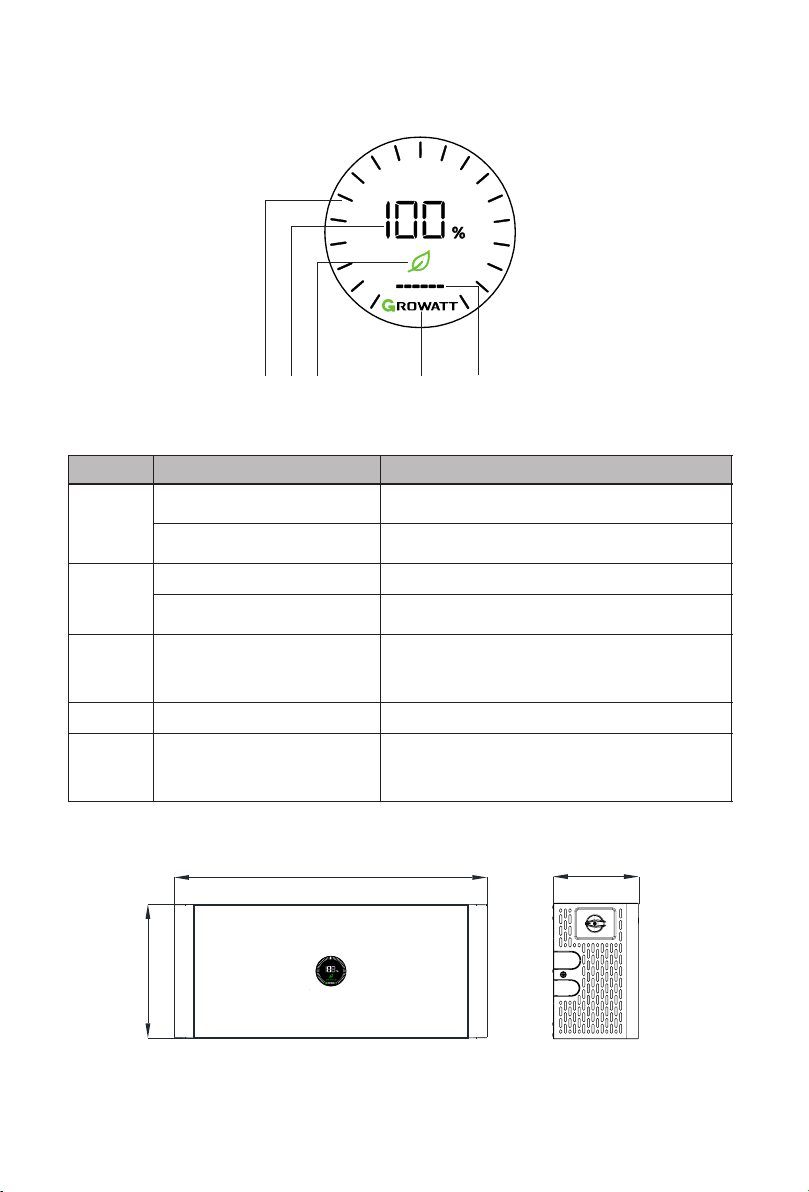
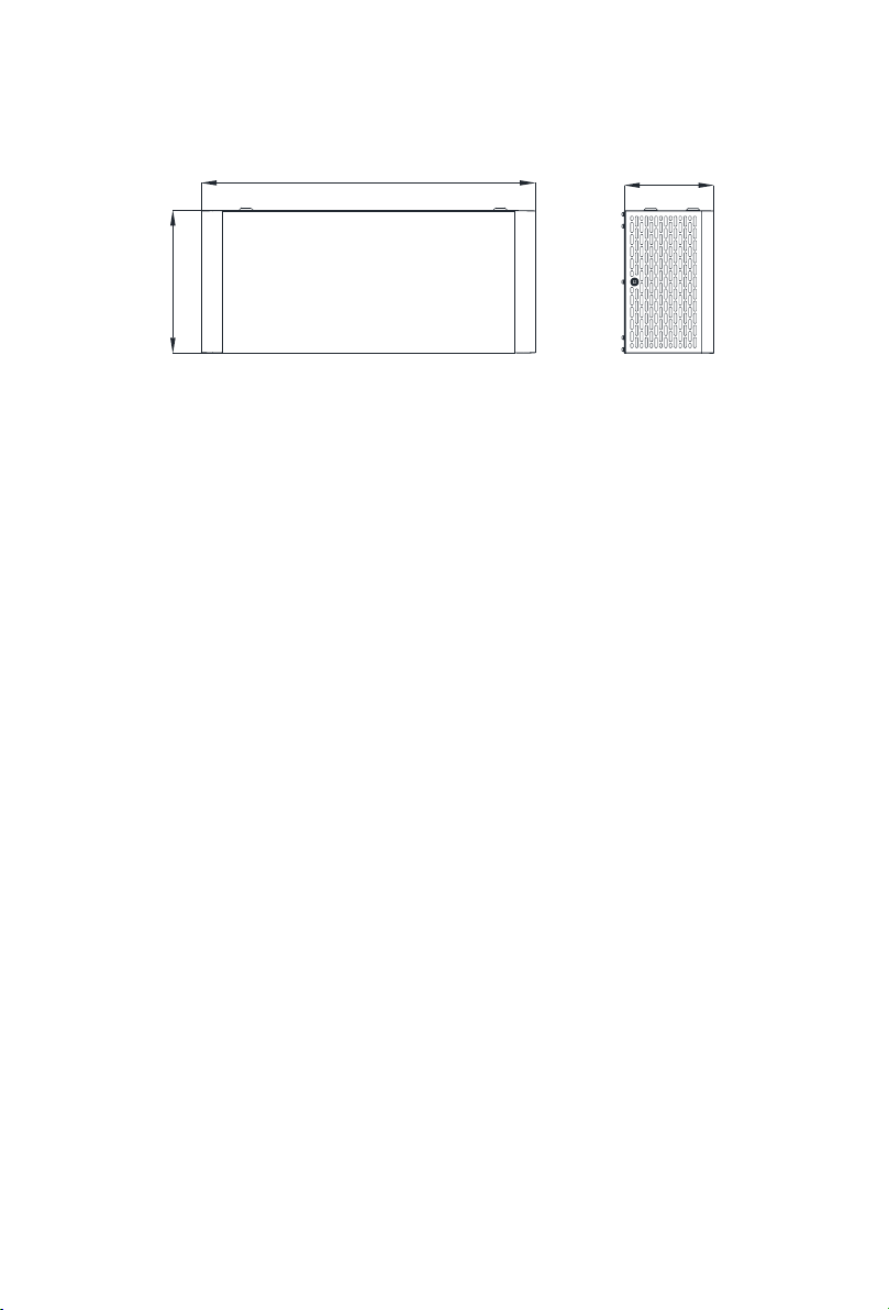
Dimensions (unit: mm)
Figure 1-6: Dimensions of APX 5.0P-B1-US
56
690 185
295