Alpha 838W User manual

12.12.2022
BOX “D” - JACK CYLINDER KIT: MODEL 838W / 868W
THIS BOX CONTAINS THE FOLLOWING:
1 Hydraulic Ram - 24.5” 1 Hex Key Wrench
1 3.5” Support Collar 4 3/8 x 16 x 1” Bolt
3 24” Braces 3 3/8 x 16 x 1-1/4” Bolts
1 1.25” Locking Safety Collar 9 3/8 X 16 Nuts
1 6” Top Ram Extension 8 3/8 Lock Washers
1 Jack Pump Handle 1 7” Pump Handle Storage Pin
BOLT NUT WASHER
JAM NUT CONFIGURATION
BOLT NUT WASHER
JACK BRACE
SUPPORT COLLAR
BASE
3/8”
NUT
3/8” LOCK
WASHER
HANDLE STORAGE PIN
26” Starting Height
Step 1: Mount the Hydraulic Ram to the Base Frame by bolting through the bottom of
the frame into the existing hole in the cylinder bottom using a jam nut
configuration; one (1) each 3/8 x 16 x 1” bolts, 3/8 x 16 nuts and 3/8 lock washers.
Step 2: Install the Wheel Kit (“F/K”ÊinstructionÊsheet)
Step 2: Install each of the 24” Braces to the inner holes on the Base Frame with jam nuts using 1” bolts.
Step 3: Slide the 3.5” centering collar over the top of the Hydraulic Ram and attach each of the 24” braces to
the centering collar with jam nuts (3) using 1-1/4” bolts. Finger tighten.
Step 4: Center the Hydraulic Ram inside the centering collar bringing the bolts into firm contact with the
cylinder. *Do not over tighten*
Step 5: Install the jack pump handle storage pin in any open hole using the 7” pump handle storage pin and
one (1) each of the 3/8 x 16 nuts and 3/8 lock washers as shown below.
Check All Jam Nuts To Ensure They Are Tight
Please READ and follow the jacking instructions before using.
CopiesÊofÊtheÊinstructionÊsheetsÊareÊavailableÊonÊourÊwebsite:Êwww.alphaaviation.com
SEE BACK SIDE FOR ADDITIONAL STARTING HEIGHTS
BOX “D” INSTRUCTIONS
838W / 868W

12.12.2022
BOX “D”
838W - Box “G” 6” Welded Riser (NoÊInstructionÊSheet)
38” Starting Height; Install the 6.25” Welded Riser between the Ram Cylinder and Base Frame using the 7”
bolt and 3/8” lock washer provided with Box G and a 3/8” nut.
868W
32” starting height; Add the 6” Riser Tube and Riser End Caps. See Box “H” Assembly Instructions.
38” starting height; Add the 6” Riser Tube and Riser End Caps. See Box “H” Assembly Instructions.
Attach the 6” Top Ram Extension to the top of the Ram. Secure with Set Screws.
68” starting height; Add the 30” Riser Tube and Riser End Caps. (Boxes “H” and “J”)
Add the 6” Top Ram Extension. Secure with Set Screws (Box “D”)
868W
26” Configuration
868W
38” Configuration
868W
68” Configuration
SPLIT
LOCKING
COLLAR
6” TOP RAM
EXTENSION
3.5” CENTERING
60” BRACE
(3)
24” BRACE
36” RISER
3” CENTERING
WHEEL KIT
JACK PUMP
RISER
RISER
END CAP

12.12.2022
BOX “H” - MODEL 368W / 868W / 868HLW RISER TUBES & END CAPS
THIS KIT CONTAINS THE FOLLOWING:
Single Pack
1 6” Riser Tube 2 6” Riser Tubes
2 Riser Tube End Caps 4 Riser Tube End Caps
4 3/8” x 16 x 1” Bolts 8 3/8” x 16 x 1” Bolts
4 3/8” x 16 Nuts 8 3/8” x 16 Nuts
Double Pack
4 3/8” Lock Washers 8 3/8” Lock Washers
ASSEMBLY
Step 1: Mount the hydraulic ram to one of the riser caps by bolting through the cap into the existing hole in the cylinder
bottom using the jam nut configuration as shown below; one (1) each of the 3/8 x 16 x 1” bolts, 3/8 x 16 nuts
and 3/8 lock washers.
Step 2: Mount the triangular base to one of the base riser caps by bolting through the riser cap and frame
using the jam nut configuration.
Step 3: Install the 6” riser tube in the riser cap attached to the frame. Using the jam nut configuration,
tighten to secure the riser tube in place.
Step 4: Install the hydraulic ram, with riser cap attached, to the top of the riser tube securing it to the riser
with the jam nut configuration.
Step 5: Complete the jack assembly per the instructions supplied with other jack components.
BOLT NUT WASHER
JAM NUT CONFIGURATION

12.12.2022
THIS KIT CONTAINS THE FOLLOWING:
1 30” Riser Tube 7 3/8” x 16 x 1” Bolts
1 3” Centering Collar 7 3/8” x 16 Nuts
3 60” Braces 7 3/8” Lock Washers
2 Riser Tube End Caps
BOLT NUT WASHER
JAM NUT CONFIGURATION
BOX “M” - MODEL 868HLW LONG RISER & BRACES KIT
62” Starting Height
Step 1: Mount one of the Riser End Caps to the bottom of the Hydraulic Ram by bolting
through the end cap into the existing hole in the bottom of the ram cylinder using the jam nut
configuration shown below; one (1) each 3/8” x 16 x 1” bolt, 3/8” x 16 nut and 3/8” lock washer.
Set aside.
Step 2: Mount the remaining Riser End Cap to the Base Frame using a jam nut (1).
Step 3: Install the Wheel Kit. (“F/K”ÊinstructionÊsheet)
Step 4: Install each of the 24” braces to the inner set of holes on the base frame using jam nuts (3).
Step 5: Place the 30” Riser Tube into the Riser End Cap mounted onto the Base Frame, securing it
with jam nuts (3)
Step 6: Slide the 3” Centering Collar over the 30” riser tube. Attach each of the 24” braces with
jam nuts (3), making sure the riser tube stays centered inside the centering collar. Tighten the jam
nuts, brace to collar, securing the braces firmly.
Step 7: Place the Hydraulic Ram with Riser End Cap on top of the 30” riser and secure it using jam nuts(3).
Step 8: Slide the 3.5” Centering Collar over the Hydraulic Ram.
Step 9: Install each of the 60” Braces to the outer set of holes on the Base Frame using jam nuts (3).
Step 10: Slide the 3.5” Centering Collar over the Hydraulic Ram. Attach each of the 60” Braces using jam
nuts, making sure the collar is centered around the cylinder. Tighten the jam nuts, brace to collar,
securing the braces firmly. *Do not over tighten*
Step 11: Put the locking collar on the piston.
Check all jam nuts to ensure they are all tight.
Please READ and follow the Jacking Instructions before using.
CopiesÊofÊtheÊinstructionÊsheetsÊareÊavailableÊonÊourÊwebsite:Êwww.alphaaviation.com
SEE BACK SIDE FOR ADDITIONAL STARTING HEIGHTS

12.12.2022
BOX “M” - Cont’d
68” STARTING HEIGHT
Step 1: Mount one of the Riser End Caps to the bottom of the Ram Cylinder by bolting through the end cap
into the existing hole in the bottom of the cylinder using the jam nut configuration shown below;
one (1) each 3/8” x 16 x 1” bolt, 3/8” x 16 nut and 3/8” lock washer.
Set aside.
Step 2: Take 2 of the riser end caps, place them back to back and join them with a jam nut (1).
Set Aside.
Step 3: Mount the remaining Riser End Cap to the Base Frame using a jam nut (1).
Step 4: Install the wheel kit. (“F/K”ÊinstructionÊsheet)
Step 5: Insert the 30” Riser Tube into the Riser End Cap mounted to the Base
Frame. Secure with jam nuts (3).
Step 6: Install the 24” braces (3) to the inner set of holes on the Brace Frame using jam nuts (3).
Step 7: Slide the 3” Centering Collar over the 30” Riser Tube. Mount the 24” Braces to it using jam nuts (3).
Step 8: Place the 2 Riser End Caps that are connected on top of the 30” Riser Tube. Secure with jam nuts (3).
Step 9: Insert the 6” Riser Tube into the Riser End Cap. Secure with jam nuts (3).
Step 10: Place the Ram Cylinder with Riser End Cap onto the 6” Riser Tube. Secure with jam nuts (3).
Step 11: Install each of the 60” Braces to the outer set of holes on the Base Frame using jam nuts (3).
Step 12: Slide the 3.5” Centering collar over the Ram Cylinder. Attach each of the 60” Braces using jam
nuts. Make sure the collar is centered around the cylinder. Tighten the jam nuts, brace to collar,
securing the braces firmly. *Do not over tighten*
Step 13: Put the locking collar on the piston.
Check all jam nuts to ensure they are all tight.
32” starting Height - Ram Cylinder, Base Frame, 24” Braces (3)
ReferÊtoÊtheÊBoxÊ“A”Ê&Ê“F/K”
38” Starting Height - Ram Cylinder, Base Frame, 24” Braces (3), 6” Riser Tube, Riser End Caps (2)
ReferÊtoÊtheÊBoxÊÊ“A”,Ê“F/K”ÊandÊ“H”Ê
Please READ and follow the jacking instructions before using.
CopiesÊofÊtheÊinstructionÊsheetsÊareÊavailableÊonÊourÊwebsite:Êwww.alphaaviation.com

12.12.2022
JACKING INSTRUCTIONS
CAUTION:
Jacking of aircraft and working around or under jacked aircraft are hazardous work operations
and should only be attempted by experienced personnel.
IF IN DOUBT, SEEK EXPERIENCED INDIVIDUALS TO HELP YOU
RAISING:
Always jack on a level surface.
Center the jack under the aircraft jack point.
When all required jacks are in place, jack the aircraft evenly, using multiple personnel or moving
from jack to jack, as needed, to maintain a relatively level attitude.
When the aircraft is at the desired height, engage the safety collars using the following method:
Lower the safety collar into a position 1/8” above the cylinder and tighten securely.
Slowly release the pressure in the ram. Lower the load onto the collar, to determine if the collar is
tight enough to support the load.
If the load is held; pump the jack handle enough to restore pressure to the ram - taking the load off
of the safety collar.
If the load slips at all; raise the load off of the safety collar, retighten and re-test as above.
LOWERING:
Pump the jack handle to raise the load off of the safety collar.
Loosen the safety collar bolts, to allow the collar to slide up the ram as it is lowered.
Slowly lower the aircraft, evenly, using multiple personnel or moving from jack to jack, as needed,
to maintain a relatively level attitude.
Safely slide the jacks from under the aircraft.

12.12.2022
PRODUCT WARRANTY
Each aircraft jack and tail weight produced and sold by Alpha Aviation Inc. (AAI) is unconditionally
warranted against defects in material and workmanship for a period of one year, from the date of
purchase.
Items which are found to be defective will be either repaired or replaced at the discretion of Alpha
Aviation Inc.
All items returned to AAI for any reason should be shipped freight prepaid. All items repaired or
replaced will be returned to the customer by AAI, freight pre-paid.
SATISFACTION GUARANTEE
Alpha Aviation Inc. is dedicated to producing products, which meet or exceed the customer’s
expectations. Therefore, each and every product is sold on a 30-day satisfaction guaranteed basis.
Should a product not meet the customer’s expectation or application, a full refund of the purchase
price will be made upon the return of the product in resalable condition.
All products returned under the terms of this satisfaction guarantee must be returned freight pre-paid.
ACKNOWLEDGEMENTS AND DISCLAIMERS
DANGEROUS ACTIVITY ACKNOWLEDGEMENT
THE PURCHASER ACKNOWLEDGES THAT HE OR SHE IS AWARE THAT ACTIVITIES
THAT INVOLVE THE JACKING, RAISING OR SUPPORTING OF AIRCRAFT ARE INHER-
ENTLY DANGEROUS ACTIVITIES, AND THAT SUCH ACTIVITIES CAN RESULT IN
PROPERTY DAMAGE, PERSONAL INJURY AND DEATH.
DAMAGE AND INJURY DISCLAIMER
Alpha Aviation Inc. disclaims responsibility for any and all injuries or damage, which may result
from the use of its products. This disclaimer includes damages and injuries that are either a direct
result or consequential to the use of the product.
PRODUCT APPLICATION ACKNOWLEDGEMENT
The purchaser acknowledges that; the products provided by Alpha Aviation Inc. are furnished with
no warranty as to application or suitability for any specific purpose.
The purchaser further acknowledges that; Alpha Aviation Inc listing of applications is offered as a
guide and the final decision as to the suitability of any product for a specific task is the sole
responsibility of the user.
The purchaser further acknowledges; that Alpha Aviation Inc. has no control over the products
location, use or the expertise of the person using the product.

12.12.2022
SUGGESTED JACK TESTING and REFILL PROCEDURES
CHECKING OIL LEVEL
The easiest method is to simply pump the unloaded jack to its maximum length.
If the jack reservoir contains adequate oil it will reach its full extended length and the jack handle will
become difficult to pump as you will feel the oil bypassing.
If the jack reservoir contains inadequate oil it will not reach its full extended length and the jack handle
will be less difficult to pump and the ram will not advance upward.
ADDING HYDRAULIC JACK OIL
Stand the jack on its base and carefully remove the rubber drain plug by twisting as you work it out from the
side of the jack body.
Place the jack on its side with the fill hole up and add oil using a small funnel.
An ounce of oil will gain you about an inch of lift – do not over fill – As you add oil periodically stand the
jack up and pump it to determine if it has adequate oil to reach full extension.
If the jack reservoir contains adequate oil it will reach its full extended length and the jack handle will
become difficult to pump as you will feel the oil bypassing.
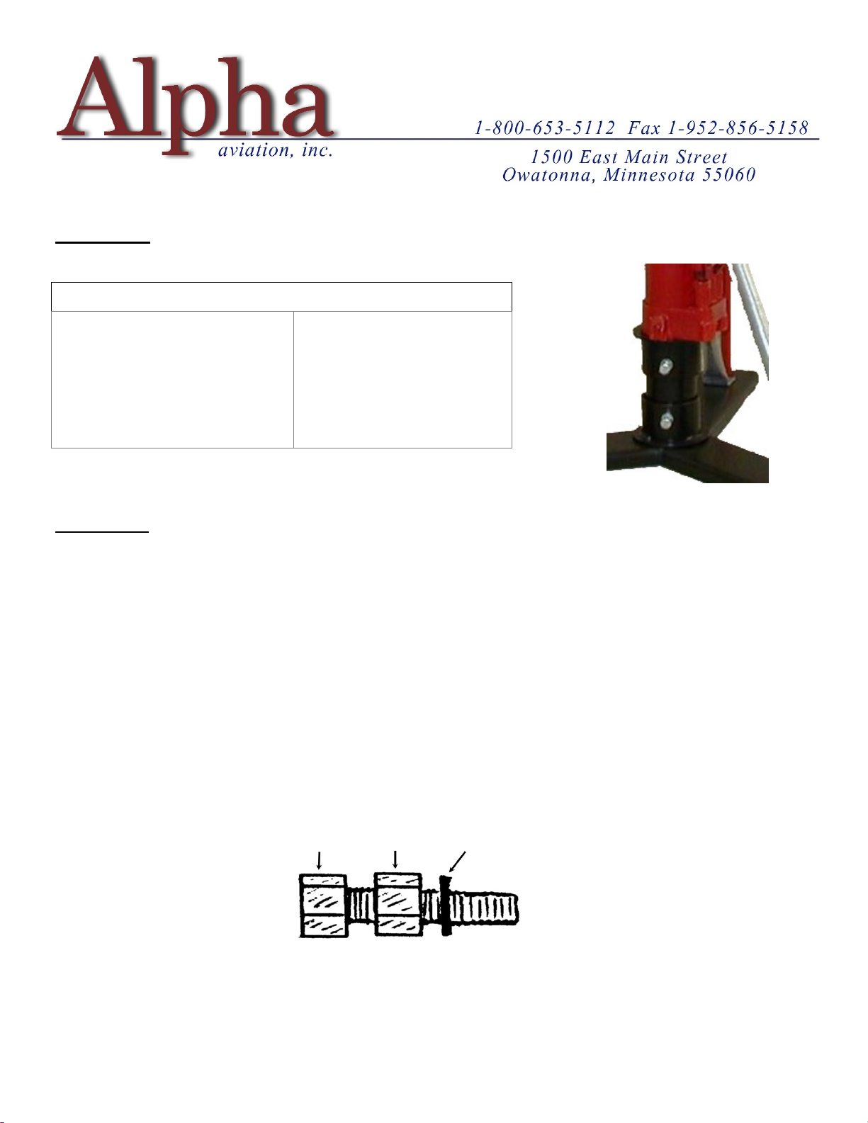
When filled, carefully reinstall the plug. Place the plug at a slight angle to the hole and assist the bulbous
end into the hole using a small flat blade screw driver. Once it is started twist and push the plug until it is
seated against the jack housing.
HOW MUCH OIL WILL I NEED & WHAT OIL SHOULD I USE?
From empty, depending on the model, each jack will take between 1 and 2 quarts of commercially available
hydraulic jack oil (10W). If a commercial product is unavailable 10W Mineral Oil or 10W non-detergent
motor oil can be substituted.
MY JACK ONLY RISES ON ONE STROKE - NOT BOTH
That is a common problem when a new jack is placed into service. Long ram jacks are designed to be used
in the vertical but by necessity are shipped in the horizontal.
What has happened is that air has entered the hydraulic chamber and an air lock has occurred. To clear the
air lock, pump the jack up about 12”, open the valve and physically push the Ram down, you should hear a
burp. Retest.
If the problem has not cleared, next place the jack on the floor, open the valve and manually pull the Ram
up out of the cylinder to its full extension. This will pull oil from the reservoir through both pump chambers
and into the ram chamber.
At this point, manually push the Ram down to the bottom of its stroke – listen for air (Burp) toward the end
of the stroke. Retest.
If the problem has not cleared please call for assistance, repair or replacement.

12.12.2022
RESEAL PROCEDURES
LEAKING PUMP PISTON SHAFT
Do not drain jack oil.
Place the jack on its side with the pistons up and the valve chamber elevated to drain the oil from the
valve section into the reservoir.
Remove the rocker assembly pins as necessary to gain access to the piston shaft and remove the leaking
piston.
Replace the seal or seals as appropriate and carefully reinstall the piston.
Note – when reinstalling a Double Seal assembly, if the cup is difficult to reinsert it is advisable to
remove the pump housing from the valve body, remove any paint and/or burrs from the piston shaft
and reinsert the piston from the bottom to avoid damaging the new seal.
Reassemble the rocker assembly and preform an operational test.
LEAKING or WORN CONTROL VALVE SEAL
Do not drain the jack oil.
Place jack on its back with the control valve up and the valve chamber elevated to drain the oil from the
valve section into the reservoir. Remove the control valve pin and viewing through the hole you will
see the seal.
With a small screw driver or pick push the seal in enough to roll it sideways and pick it out. Remove
the check ball and clean the chamber with spray carb or brake cleaner; reinstall the check ball.
Install the new seal using a small Philips screw driver or rod as a guide. Do not push it all the way in;
it can block the oil return path. Stop 6 or 7 threads down as the Control Pin will force it into position.
Clean and lubricate the control pin and reinstall. and test.
WORN RAM SEALS, LEAKING TOP GLAND or HOUSING
Drain the Oil
Caution – The bottom housing seal and the Ram vinyl Support Seal are directional.
Stand the jack on its base and carefully remove the rubber drain plug by twisting as you work it out
from the side of the jack body.
Place the jack on its side over a bucket and drain.
Lock the Valve Body in a large vice and remove the top Gland.
Slide out the Gland and Ram as an assembly.
Remove paint from Ram and deburr prior to reassembly
Remove the outer Housing, the Ram Cylinder tube can remain attached to the Valve Body.
Replace -
· Ram, Lower “O” Ring and vinyl Support.
· Valve Body to Housing base seal
· Top Gland to Ram interior “O” Ring
· Top Gland to Housing vinyl seal.
· Reassemble - Refill and test.
This manual suits for next models
1
Table of contents
Other Alpha Jack manuals
Popular Jack manuals by other brands

Tractel
Tractel top BT 1.5 Installation, operating and maintenance manual

HEIN-WERNER AUTOMOTIVE
HEIN-WERNER AUTOMOTIVE HW93659 Operating instructions & parts manual

Lippert
Lippert 285318 Installation and owner's manual

Tektronix
Tektronix Keithley HV-CS-1589 Installation information

kincrome
kincrome K12162 manual

U-Line
U-Line H-1545 manual