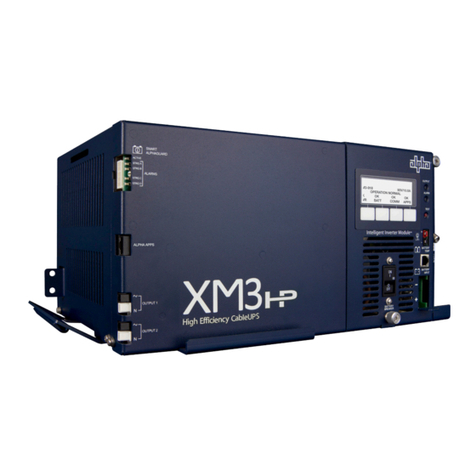
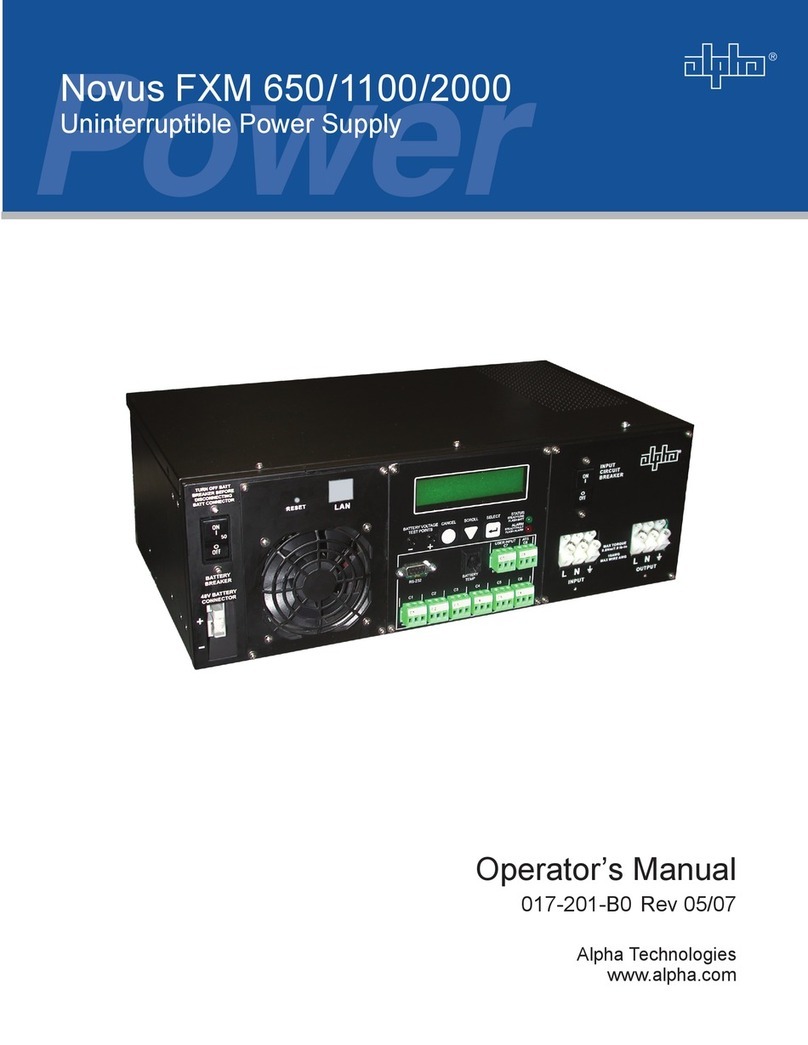
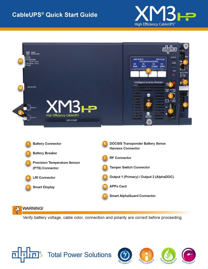
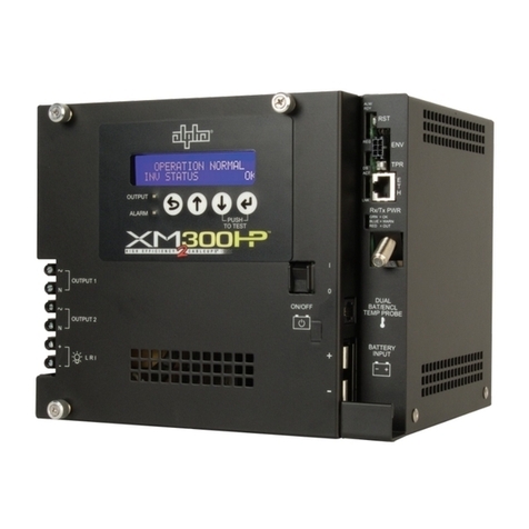
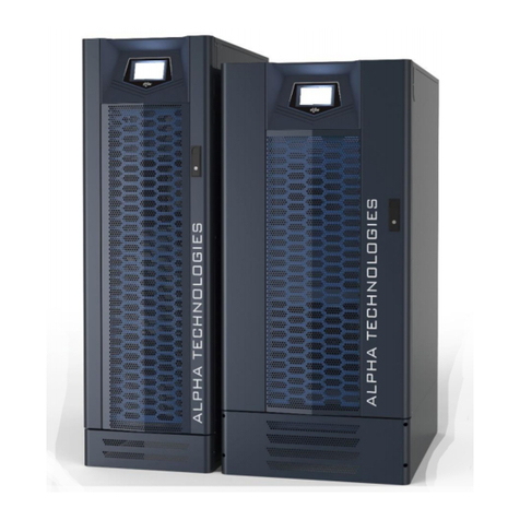
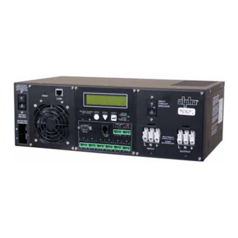
Alpha FXM HP User manual

Alpha®FXM HP
Uninterruptible Power Supply Modules
User Guide ID: 0170022-J0
Eective:11/2023
Read this document carefully.
Learn how to protect your equipment from damage and fully understand its functions.

Copyright notice
© 2023 Alpha Technologies Ltd., an EnerSys company. All Rights Reserved.
The material contained in this document is for information only and is subject to change without notice. Alpha®
reserves the right to make changes in the product design without reservation and without notification to its
users.

Contents
1. Safety....................................................................................................................................................... 6
2. Introduction........................................................................................................................................... 10
2.1. Document scope.......................................................................................................................... 10
2.2. Overview.......................................................................................................................................10
3. Alpha® FXM HP UPS module specifications.................................................................................... 12
3.1. Alpha® FXM HP 650 UPS module specifications....................................................................... 12
3.2. Alpha® FXM HP 1100 UPS module specifications......................................................................15
3.3. Alpha® FXM HP 2000 UPS module specifications..................................................................... 19
3.4. Automatic voltage regulation (AVR) transition............................................................................. 23
4. Features.................................................................................................................................................26
4.1. Alpha FXM HP 650 UPS module front panel.............................................................................. 26
4.2. Alpha® FXM HP 1100 UPS and FXM HP 2000 UPS module front panel................................... 26
4.3. Feature description.......................................................................................................................27
4.4. Dry contact description................................................................................................................ 28
5. Inspection.............................................................................................................................................. 32
6. Installation............................................................................................................................................. 33
6.1. Installation.....................................................................................................................................33
6.1.1. Tools required.....................................................................................................................33
6.2. Mounting the Alpha® FXM HP UPS module............................................................................... 33
6.2.1. Rotate the control panel.................................................................................................... 35
6.3. Wiring external batteries.............................................................................................................. 37
6.4. Wiring the Alpha® FXM HP UPS module................................................................................... 39
6.5. Alpha® Universal Automatic Transfer Switch (UATS) and Universal Generator Transfer Switch
(UGTS) device option..........................................................................................................................40
7. Operating the Alpha® FXM HP UPS module.....................................................................................41
7.1. Switching the Alpha® FXM HP UPS module on and off............................................................. 41
8. Getting Started......................................................................................................................................43
8.1. Navigating the Alpha® FXM HP UPS module user interface...................................................... 43
8.1.1. Sign in to the controller system......................................................................................... 43
8.1.2. Overview of the LCD panel interface................................................................................ 43
8.1.3. Overview of the web interface........................................................................................... 55
8.2. Email notification.......................................................................................................................... 62
Page 2 0170022-J0 Rev B

Alpha® FXM HP Uninterruptible Power Supply (UPS) Modules
8.3. Setup SNMP communication....................................................................................................... 65
9. Alpha® FXM HP UPS system..............................................................................................................67
9.1. Guidelines for setting up the Alpha® FXM HP UPS system....................................................... 67
9.1.1. The system mode.............................................................................................................. 67
9.2. Alpha® FXM HP UPS module functions..................................................................................... 69
9.2.1. Modules, inventory, and system functions......................................................................... 69
9.2.2. Battery charging................................................................................................................. 70
9.2.3. Battery temperature compensation....................................................................................71
9.2.4. Battery test......................................................................................................................... 71
9.2.5. Battery runtime and health estimation............................................................................... 73
9.2.6. AC output........................................................................................................................... 73
9.2.7. Inverter control................................................................................................................... 74
9.2.8. Load shedding relays.........................................................................................................75
9.2.9. External fan........................................................................................................................ 75
9.2.10. Keep alive........................................................................................................................ 76
9.3. Create an Alpha® FXM HP UPS system manually.....................................................................77
9.3.1. Quick reference for configuring an Alpha® FXM HP UPS system.................................... 78
9.3.2. Alpha® FXM HP UPS system default values....................................................................79
9.3.3. Create an Alpha® FXM HP UPS system.......................................................................... 83
9.3.4. Configure the battery parameters...................................................................................... 85
9.3.5. Configure the battery temperature sensors....................................................................... 86
9.3.6. Configure the charging system function............................................................................ 86
9.3.7. Configure the elevated absorption charging system......................................................... 87
9.3.8. Configure the temperature compensation system function............................................... 87
9.3.9. Running battery tests.........................................................................................................87
9.3.10. Configure battery runtime and health estimation.............................................................89
9.3.11. Configure AC shutdown................................................................................................... 89
9.3.12. Configure the external fan............................................................................................... 90
9.3.13. Configure keep alive........................................................................................................ 91
9.3.14. Configure soft shutdown.................................................................................................. 91
9.3.15. Configure SNMP UPS management information base....................................................91
9.3.16. Configure relays............................................................................................................... 92
9.3.17. Configure power outage alarm delay...............................................................................94
10. Maintaining the controller system....................................................................................................95
0170022-J0 Rev B Page 3

Alpha® FXM HP Uninterruptible Power Supply (UPS) Modules
10.1. Ethernet communications...........................................................................................................95
10.1.1. Connect via the web interface......................................................................................... 96
10.2. Working with alarms, alerts, and hints.......................................................................................96
10.2.1. Active alarms....................................................................................................................96
10.2.2. Alarm cut-off (ALCO)....................................................................................................... 97
10.2.3. Alarm activation delay at start up.................................................................................... 97
10.2.4. Alarm summary relays..................................................................................................... 97
10.2.5. Create user alarms.......................................................................................................... 99
10.3. Controller system maintenance................................................................................................100
10.3.1. Restart the controller system......................................................................................... 100
10.3.2. Restart the controller system via the LCD panel........................................................... 101
10.3.3. Change the time and date............................................................................................. 101
10.3.4. Change user interface strings........................................................................................102
10.3.5. Change the web session language............................................................................... 103
10.3.6. Change the system status bar.......................................................................................103
10.3.7. Change the dashboard values.......................................................................................103
10.3.8. Replace the controller system battery........................................................................... 104
10.3.9. Replace the fan..............................................................................................................106
10.4. Working with logs.....................................................................................................................107
10.4.1. Events and alerts logs................................................................................................... 108
10.4.2. Battery activity log..........................................................................................................108
10.4.3. Power outage log...........................................................................................................109
10.4.4. Datalogs......................................................................................................................... 110
10.4.5. Performance logs........................................................................................................... 112
10.5. File maintenance...................................................................................................................... 113
10.5.1. File preferences............................................................................................................. 113
10.5.2. File maintenance from the LCD panel...........................................................................113
10.5.3. Upgrade the controller system software........................................................................ 115
10.5.4. Upload the software manual.......................................................................................... 116
10.5.5. Export a configuration file.............................................................................................. 116
10.5.6. Import a configuration file.............................................................................................. 118
10.5.7. Export diagnostic information.........................................................................................120
10.5.8. Export inventory file....................................................................................................... 120
10.5.9. Create configuration restore points................................................................................121
Page 4 0170022-J0 Rev B

Alpha® FXM HP Uninterruptible Power Supply (UPS) Modules
10.6. User account maintenance...................................................................................................... 122
10.6.1. Set up users and permissions....................................................................................... 122
10.6.2. Edit user permissions.....................................................................................................122
10.6.3. Enable new users.......................................................................................................... 122
10.6.4. Disable users................................................................................................................. 123
10.6.5. Change the default password from the LCD panel....................................................... 123
10.6.6. Change the default password from the web interface................................................... 124
10.6.7. User account password requirements........................................................................... 124
10.6.8. Remote configuration lockout........................................................................................ 124
10.6.9. Backup and restore........................................................................................................125
10.7. Module firmware upgrades.......................................................................................................126
10.7.1. Module firmware upgrade.............................................................................................. 126
10.7.2. Upload a firmware file....................................................................................................126
10.7.3. Select the file to upgrade...............................................................................................126
10.7.4. Upgrade the module...................................................................................................... 127
11. Appendix A - Triggers......................................................................................................................128
0170022-J0 Rev B Page 5

1. Safety
Save these instructions: This document contains important safety instructions that must be followed
during the installation, servicing, and maintenance of the product. Keep it in a safe place. Review the
drawings and illustrations contained in this document before proceeding. If there are any questions
regarding the safe installation or operation of this product, contact Alpha Technologies Ltd. or the nearest
Alpha® power system representative.
Safety wording and symbols
To reduce the risk of injury or death, and to ensure the continued safe operation of this product, the
following symbols have been placed throughout this document. Where these symbols appear, use extra
care and attention.
Attention: The use of attention indicates specific regulatory requirements that may affect the
placement of equipment or installation procedures. Follow the prescribed procedures to avoid
equipment damage or service interruption.
Notice: A notice provides additional information to help complete a specific task or procedure or
general information about the product.
CAUTION: Cautions indicate the potential for injury to personnel.
Warning: Risk of serious injury or death. Equipment in operation poses a potential electrical
hazard which could result in serious injury or death to personnel. This hazard may continue even
when power is disconnected.
CAUTION: Risk of burns. A device in operation can reach temperature levels which could cause
burns.
General warning and cautions
Warning: You must read and understand the following warnings before installing the system and
its components. Failure to do so could result in personal injury or death.
Warning: This system is designed to be installed in a restricted access location that is
inaccessible to the general public.
Ce système est conçu pour être installé dans un endroit à accès restreint inaccessible au grand
public.
Page 6 0170022-J0 Rev B

Alpha® FXM HP Uninterruptible Power Supply (UPS) Modules | 1 - Safety
Warning: This equipment is not suitable for use in locations where children are likely to be
present.
Cet équipement ne convient pas pour une utilisation dans des lieux ou des enfants sont
susceptibles d’être présents.
•Read and follow all instructions included in this document.
•Only trained personnel are qualified to install or replace this equipment and its components.
•Use proper lifting techniques whenever handling equipment, parts, or batteries.
•Alpha® FXM HP Uninterruptible Power Supply (UPS) models are certified as a part of a rack
mounted uninterruptible power supply system where the suitability of the combination is to be
determined in the end application by the local authority having jurisdiction.
Electrical safety
Warning: Hazardous voltages are present at the input of power systems. The DC output from
some UPS devices and batteries can have high voltage and high short-circuit current capacity
that may cause severe burns and electrical arcing.
Warning: Lethal voltages are present within the system. Always assume that an electrical
connection or conductor is energized. Check the circuit with a voltmeter with respect to the
grounded portion of the enclosure (both AC and DC) before performing any installation or removal
procedure.
Warning: Risk of electric shock. Do not remove the cover. The Alpha® FXM HP UPS module has
no user serviceable parts inside. Refer to qualified service personnel.
Warning: Risk of electric shock. The UPS equipment powered by this service panel requires the
neutral to be bonded to ground. Disconnect the UPS DC batteries before servicing this panel.
This is applicable to the following permanently connected models: Alpha® FXM HP 2000 UPS,
FXM HP 650-48 UPS, and FXM HP 650-24 UPS.
Before working with any live battery or power system, follow these precautions:
•Remove all metallic jewelry, such as watches, rings, metal rimmed glasses, or necklaces.
•Wear safety glasses with side shields at all times during the installation.
•Use Occupational Health and Safety Association (OSHA®) approved insulated hand tools. Do not
rest tools on top of batteries.
0170022-J0 Rev B Page 7

Alpha® FXM HP Uninterruptible Power Supply (UPS) Modules | 1 - Safety
•Do not work alone under hazardous conditions.
•A licensed electrician is required to install permanently wired equipment. Input voltages can range
up to 240 VAC. Ensure that the utility power is disconnected and locked out before performing any
installation or removal procedure.
•Ensure that no liquids or wet clothes come into contact with internal components.
•Hazardous electrically live parts inside this unit are energized from the batteries even when the AC
input power is disconnected.
•Always assume electrical connections or conductors are live. Turn off all circuit breakers and
double-check with a voltmeter before performing installation or maintenance.
•Place a warning label on the utility panel to warn emergency personnel that a reserve battery
source is present which will power the loads in a power outage condition or if the AC disconnect
breaker is turned off.
•At high ambient temperature conditions, the internal temperature can be hot so use caution when
touching the equipment.
•The Alpha® FXM HP UPS module shall be connected to a dedicated branch circuit.
•Branch rated circuit overcurrent protection for the AC input and AC output circuit shall be provided
in the end installation.
•A disconnect switch shall be provided in the end installation for the AC input and AC output circuit.
•When stranded wires are used on the input and output terminal blocks, ferules or equivalent crimp
terminal must be used.
Battery safety
Warning: Follow battery manufacturer’s safety recommendations when working around battery
systems. Do not smoke or introduce an open flame when batteries (especially vented batteries)
are charging. When charging, batteries vent hydrogen gas, which can explode.
Notice: Read the material safety data sheet (MSDS) for any batteries used in the system before
installation. The MSDS provides important information including hazard identification, first aid
measures, handling and storage, and personal protective equipment (PPE).
•Never transport an enclosure with batteries installed. Batteries must only be installed after the
enclosure has been securely set in place at its permanent installation location. Transporting the
unit with batteries installed may cause a short circuit, fire, explosion, or damage to the battery
pack, enclosure and installed equipment.
Page 8 0170022-J0 Rev B

Alpha® FXM HP Uninterruptible Power Supply (UPS) Modules | 1 - Safety
•Servicing and connection of batteries must be performed by, or under the direct supervision of,
personnel knowledgeable of batteries and the required safety precautions.
•Batteries contain or emit chemicals known to cause cancer and birth defects or other reproductive
harm. Battery post terminals and related accessories contain lead and lead compounds. Wash
your hands after handling batteries.
•Batteries are hazardous to the environment and should be disposed at a recycling facility. Consult
the battery manufacturer for recommended local authorized recyclers.
0170022-J0 Rev B Page 9

2. Introduction
2.1. Document scope
This document covers the features, options, installation, and startup of the Alpha® FXM high performance
family of rugged uninterruptible power supplies (UPS). Images contained in this document are for
illustrative purposes only and may not exactly match your installation. This document covers the following
Alpha® FXM HP UPS models:
•Alpha® FXM HP 650 UPS, 24VDC: With a 24 VDC battery string voltage (120 VAC and 230 VAC)
•Alpha® FXM HP 650 UPS, 48VDC: With a 48 VDC battery string voltage (120 VAC)
•Alpha® FXM HP 1100 UPS, 48VDC: With a 48 VDC battery string voltage (120 VAC and 230
VAC)
•Alpha® FXM HP 2000 UPS, 48VDC: With a 48 VDC battery string voltage (120 VAC and 230
VAC)
2.2. Overview
About battery backup systems and uninterruptible power supplies
Battery backup systems (BBS) and uninterruptible power supply (UPS) modules are the first line of
defense to keep critical loads backed up during power outages as well as increasing equipment reliability
by protecting them against power disturbances. Battery backup systems need to be rugged, reliable,
and informative in the data they provide. Typical applications include traffic infrastructure, intelligent
tranportation system (ITS) equipment, security devices, parking gates, ticket dispensers, variable
message signs, and AC small cell power backup. Some of the benefits of a BBS are:
•Providing continual power to your operating system in the event of a power outage, sag or brown
out, until regular utility power is restored.
•Conditioning and regulating the quality of the commercial power supply to your critical load.
•Keeping your traffic intersections and data flowing to prevent or minimize severe accidents and
downtime.
•Reducing operating expenses by eliminating false service call outs and expensive truck roll outs.
About Alpha® FXM HP UPS modules
Alpha® FXM HP UPS modules are a line of high performance rugged uninterruptible power supply
(UPS) modules for the most demanding environments where clean backup power is needed. Alpha®
FXM HP UPS modules ensure equipment in critical applications remains safe and protected from power
disturbances and outages. Some of the key features of Alpha® FXM HP UPS modules are:
•Integrated Cordex® HP controller system with full color touchscreen LCD panel
•Front panel LEDs for alarms, progress, and status indication
•Dual ethernet ports for remote or local communication
Page 10 0170022-J0 Rev B

Alpha® FXM HP Uninterruptible Power Supply (UPS) Modules | 2 - Introduction
•USB A port for upgrades or file management via a standard USB drive
•USB Mini-B port for soft shutdown using MegaTec protocol compliant client
•Independent CAN bus ports for communication with the Cordex® HP family of products
•User programmable dry contacts for control and monitoring of key functions
•Customizable user configurations that can be exported and imported to other Alpha® FXM HP
UPS modules
Peripherals
Alpha® FXM HP UPS modules can be used together with an external analog and digital input and output
peripheral to monitor electrical signals (temperature, voltage, and current) and generate electrical signals
through relays.
The most commonly used analog digital input output (ADIO) peripheral is the Cordex® HP L-ADIO (low
voltage analog digital input output) peripheral for low voltage systems. Features include:
•Eight digital inputs
•Four voltage sensors
•Four temperature sensors
•Four current sensors
•12 Form C relay outputs
Cordex® HP controller system
Alpha® FXM HP UPS modules use the advanced Cordex® HP controller system for monitoring and
control. It offers a common user interface across all Alpha® products including FXM HP UPS modules,
DC power plants, inverter systems, and line powering. This provides seamless integration of multiple
systems allowing comprehensive management and common interface using a single Internet Protocol (IP)
connection.
Notice: While referring to monitoring and control Alpha® FXM HP UPS modules or controller
systems will be used interchangeably in this document.
0170022-J0 Rev B Page 11

3. Alpha® FXM HP UPS module specifications
3.1. Alpha® FXM HP 650 UPS module specifications
Table 3-1 Alpha® FXM HP 650 UPS module specifications
FXM HP 650-24
UPS 120 VAC
FXM HP 650-24
UPS 230 VAC
FXM HP 650-48 UPS
120 VAC
Electrical input
Voltage range in line mode ±2 V 85 to 171VAC 153 to 322VAC 85 to 171VAC
Nominal frequency 50 or 60 Hz
Autodetect Frequency is the default configuration, can also be manu
ally configured.
Frequency tolerance in line mode ±5%
Maximum input current18 A 4.4 A 10.5 A
AC breaker rating 10 A 5.5 A 15 A
Maximum discharging current 36 A 36 A 16 A
Electrical output
Output voltage setting 120V 210 V, 220V, 230V,
240V
120 V
Regulation (line mode) ±10%
Regulation (inverter mode) ±2%
Rated power 650W/VA 650 W/VA 650 W/VA
Frequency 50 or 60 Hz
Battery
Battery string voltage 24 V 24 V 48 V
Maximum charging current 10 A 10 A 10 A
Battery breaker rating 80 A 80 A 50 A
Alpha® FXM HP 650 UPS - 120 V modules are evaluated with a short
circuit current rating of 5 kA.
Short circuit current rating
Alpha® FXM HP 650 UPS - 230 V modules are evaluated with a short
circuit current rating of 2 kA.
Performance
1. Measured at nominal input voltage and load.
Page 12 0170022-J0 Rev B

Alpha® FXM HP Uninterruptible Power Supply (UPS) Modules | 3 - Alpha® FXM HP UPS module specifications
Table 3-1 Alpha® FXM HP 650 UPS module specifications (continued)
FXM HP 650-24
UPS 120 VAC
FXM HP 650-24
UPS 230 VAC
FXM HP 650-48 UPS
120 VAC
Line mode efficiency2>98% >98% >97.5%
Inverter mode efficiency3>75% >75% >85%
Typical transfer time 5 ms
Voltage THD <3% <3% <3%
Waveform Pure sine wave
Load crest factor 3:1 (load dependent)
Mechanical
Dimensions H×W×D 3.47 × 17 × 9 in. (89 × 432 × 229mm)
Weight without batteries 25 lb (11.3 kg)
Mounting Shelf, rack, or wall; horizontal or vertical mount
Cooling Forced air (fan cooled) with optional external fan cooling for enclosure
Display Full graphic LCD panel, 480 × 272 pixels, resistive touchscreen
2 × RJ45: Ethernet
1 × USB A
1 × USB Mini-B
1 × RJ12 offset (CAN)
Communication ports
1 × RJ11 (battery temperature compensation)
Solid green: Line mode
Flashing green: Inverter mode
Solid yellow: Minor alarms
Status indicators (LEDs)
Solid red: Major or critical alarms
Environmental
2. Measured at nominal AC input and full load.
3. Measured at nominal DC input and full load.
0170022-J0 Rev B Page 13

Alpha® FXM HP Uninterruptible Power Supply (UPS) Modules | 3 - Alpha® FXM HP UPS module specifications
Table 3-1 Alpha® FXM HP 650 UPS module specifications (continued)
FXM HP 650-24
UPS 120 VAC
FXM HP 650-24
UPS 230 VAC
FXM HP 650-48 UPS
120 VAC
–40 to 131℉ (–40 to
55℃) at 60 Hz
–40 to 104℉ (–40 to
40℃) at 210 V
–40 to 131℉ (–40 to
55℃)
–40 to 122℉ (–40 to
50℃) at 50 Hz
–40 to 122℉ (–40 to
50℃) at 220 V
Full load operating temperature range4
–40 to 131℉ (–40 to
55℃) at 230, 240 V
Relative humidity Up to 95% (non condensing)
Elevation5Up to 12,000 ft (3,700 m)
Audible noise645 dBa at 3.3 ft (1 m)
Heat dissipation (inverter mode) 700BTU/h
(205.2W)
845 BTU/h (247.7W) 375 BTU/h (109.9W)
Connections
AC input and output connectors Terminal block, Weco PN: 324-HDS/03 or equivalent, maximum 10
AWG (6 mm²), 194℉ (90℃) rated copper wire
DC connection Quick connect, Anderson SB-50 grey housing P/N: 992, 75 A rated ter
minals PN: 5952 or equivalent, maximum 8 AWG (10 mm²)
C1 to C5 programmable NO/NC (240 VAC, 1 A maximum)
C6: 24 VDC at 500 mA, 3 user inputs
ATS: 24 VDC/10 mA
C6: 48 VDC at 500 mA, 3 user inputs
ATS: 48 VDC/10 mA
C7: User inputs
•S1: Self test
•S2: User input
•S3 Shutdown (EPO)
Dry contacts
C8: ATS
4. Derates 1.4% per ℃ past this range until a maximum of 165℉ (74℃).
5. Derates 2℃ per 1,000 ft (300 m) above 4,500 ft (1,400 m).
6. Measured at 77℉ (25℃) ambient temperature.
Page 14 0170022-J0 Rev B

Alpha® FXM HP Uninterruptible Power Supply (UPS) Modules | 3 - Alpha® FXM HP UPS module specifications
Table 3-1 Alpha® FXM HP 650 UPS module specifications (continued)
FXM HP 650-24
UPS 120 VAC
FXM HP 650-24
UPS 230 VAC
FXM HP 650-48 UPS
120 VAC
•Alpha® FXM HP 650-24 UPS module: 24 VDC at 10 mA
•Alpha® FXM HP 650-48 UPS modules: 48 VDC at 10mA
Regulatory compliance
UL 1778
CAN/CSA-C22.2 No. 107.3
Safety
EN 62040-1
FCC CFR 47 PART 15/B – Class A
CAN ICES-003(A) / NMB-003(A)
EN 62040-2 - UPS Category C2
EN 55022 (CISPR) Class A
C62.41
EMC
Note: This equipment has been tested and found to comply with the
limits for a Class A digital device, pursuant to part 15 of the FCC Rules.
These limits are designed to provide reasonable protection against
harmful interference when the equipment is operated in a commercial
environment. This equipment generates, uses, and can radiate radio
frequency energy and, if not installed and used in accordance with the
instruction manual, may cause harmful interference to radio commu
nications. Operation of this equipment in a residential area is likely to
cause harmful interference in which case the user will be required to
correct the interference at his own expense.
3.2. Alpha® FXM HP 1100 UPS module specifications
Table 3-2 Alpha® FXM HP 1100 UPS module specifications
FXM HP 1100 UPS 120
VAC
FXM HP 1100 UPS 230
VAC
Electrical input
Voltage range in line mode ±2 V 85 to 171VAC 153 to 322VAC
Nominal frequency 50 or 60 Hz
0170022-J0 Rev B Page 15

Alpha® FXM HP Uninterruptible Power Supply (UPS) Modules | 3 - Alpha® FXM HP UPS module specifications
Table 3-2 Alpha® FXM HP 1100 UPS module specifications (continued)
FXM HP 1100 UPS 120
VAC
FXM HP 1100 UPS 230
VAC
Autodetect Frequency is the default configuration, can also be
manually configured.
Frequency tolerance in line mode ±5%
Maximum input current715 A 8 A
AC breaker rating 20 A 10 A
Maximum discharging current 27 A 27 A
Electrical output
Output voltage setting 120 V 210, 220, 230, 240V
Regulation (line mode) ±10%
Regulation (inverter mode) ±2%
Rated power 1100 W/VA 1100 W/VA
Frequency 50 or 60 Hz
Battery
Battery string voltage 48 V 48 V
Maximum charging current 15 A 15 A
Battery breaker rating 50 A 50 A
Alpha® FXM HP 1100 UPS and FXM HP 2000 UPS - 120 V mod
ules are evaluated with a short circuit current rating of 5 kA.
Short circuit current rating
Alpha® FXM HP 1100 UPS and FXM HP 2000 UPS - 230 V mod
ules are evaluated with a short circuit current rating of 2 kA.
Performance
Line mode efficiency8>98% >97%
Inverter mode efficiency9>85% >85%
Typical transfer time 5 ms
Voltage THD <3% <3.5%
Waveform Pure sine wave
7. Measured at nominal input voltage and load.
8. Measured at nominal AC input and full load.
9. Measured at nominal DC input and full load.
Page 16 0170022-J0 Rev B

Alpha® FXM HP Uninterruptible Power Supply (UPS) Modules | 3 - Alpha® FXM HP UPS module specifications
Table 3-2 Alpha® FXM HP 1100 UPS module specifications (continued)
FXM HP 1100 UPS 120
VAC
FXM HP 1100 UPS 230
VAC
Load crest factor 3:1 (load dependent)
Mechanical
Dimensions H×W×D 5.22 × 15.5 × 8.75 in. (133 × 394 × 222 mm)
Weight without batteries 31 lb (14 kg)
Mounting Shelf, rack, or wall; horizontal or vertical mount
Cooling Forced air (fan cooled) with optional external fan cooling for en
closure
Display Full graphic LCD panel, 480 × 272 pixels, resistive touchscreen
2 × RJ45: Ethernet
1 × USB A
1 × USB Mini-B
1 × RJ12 offset (CAN)
Communication ports
1 × RJ11 (battery temperature compensation)
Solid green: Line mode
Flashing green: Inverter mode
Solid yellow: Minor alarms
Status indicators (LEDs)
Solid red: Major or critical alarms
Environmental
–40 to 131℉ (–40 to 55℃) at
220, 230, 240 V
Full load operating temperature range10 –40 to 122℉ (–40 to 50℃)
–40 to 113℉ (–40 to 45℃) at
210 V
Relative humidity Up to 95% (non condensing)
Elevation11 Up to 12,000 ft (3,700 m)
10. Derates 1.4% per ℃ past this range until a maximum of 165℉ (74℃).
11. Derates 2℃ per 1,000 ft (300 m) above 4,500 ft (1,400 m).
0170022-J0 Rev B Page 17

Alpha® FXM HP Uninterruptible Power Supply (UPS) Modules | 3 - Alpha® FXM HP UPS module specifications
Table 3-2 Alpha® FXM HP 1100 UPS module specifications (continued)
FXM HP 1100 UPS 120
VAC
FXM HP 1100 UPS 230
VAC
Audible noise12 45 dBa at 3.3 ft (1 m)
Heat dissipation (inverter mode) 640 BTU/h (187.6W) 675 BTU/h (197.8W)
Connections
AC input and output connectors Terminal block, Weco PN: 324-HDS/03 or equivalent, maximum
10 AWG (6 mm²), 194℉ (90℃) rated copper wire
DC connection Quick connect, Anderson SB-50 grey housing P/N: 992, 75 A rat
ed terminals PN: 5952 or equivalent, maximum 8 AWG (10 mm²)
C1 to C5 programmable NO/NC (240 VAC, 1 A maximum)
C6: 24 VDC at 500 mA, 3 user inputs
ATS: 24 VDC/10 mA
C6: 48 VDC at 500 mA, 3 user inputs
ATS: 48 VDC/10 mA
C7: User inputs
•S1: Self test
•S2: User input
•S3 Shutdown (EPO)
Dry contacts
C8: ATS
48 VDC at 10mA
Regulatory compliance
UL 1778
CAN/CSA-C22.2 No. 107.3
Safety
EN 62040-1
FCC CFR 47 PART 15/B – Class A
CAN ICES-003(A) / NMB-003(A)
EN 62040-2 - UPS Category C2
EMC
EN 55022 (CISPR) Class A
12. Measured at 77℉ (25℃) ambient temperature.
Page 18 0170022-J0 Rev B

Alpha® FXM HP Uninterruptible Power Supply (UPS) Modules | 3 - Alpha® FXM HP UPS module specifications
Table 3-2 Alpha® FXM HP 1100 UPS module specifications (continued)
FXM HP 1100 UPS 120
VAC
FXM HP 1100 UPS 230
VAC
C62.41
Note: This equipment has been tested and found to comply with
the limits for a Class A digital device, pursuant to part 15 of the
FCC Rules. These limits are designed to provide reasonable pro
tection against harmful interference when the equipment is oper
ated in a commercial environment. This equipment generates, us
es, and can radiate radio frequency energy and, if not installed
and used in accordance with the instruction manual, may cause
harmful interference to radio communications. Operation of this
equipment in a residential area is likely to cause harmful interfer
ence in which case the user will be required to correct the inter
ference at his own expense.
3.3. Alpha® FXM HP 2000 UPS module specifications
Table 3-3 Alpha® FXM HP 2000 UPS module specifications
FXM HP 2000 UPS 120
VAC
FXM HP 2000 UPS 230
VAC
Electrical input
Voltage range in line mode ±2 V 85 to 150VAC 153 to 322VAC
Nominal frequency 50 or 60 Hz
Autodetect Frequency is the default configuration, can also be
manually configured.
Frequency tolerance in line mode ±5%
Maximum input current13 20 A 12 A
AC breaker rating 25 A 15 A
Maximum discharging current 52 A 52 A
Electrical output
Output voltage setting 120 V 210, 220, 230, 240V
Regulation (line mode) ±10%
Regulation (inverter mode) ±2%
13. Measured at nominal input voltage and load.
0170022-J0 Rev B Page 19
Table of contents
Other Alpha UPS manuals

Alpha
Alpha CFR 5000 User manual

Alpha
Alpha FlexPoint FPR1207-F User manual

Alpha
Alpha FP1208-F-5A User manual

Alpha
Alpha Novus FXM 1100 User manual

Alpha
Alpha XM3 User manual

Alpha
Alpha Pinnacle Plus Series User manual

Alpha
Alpha XM 6015 Series User manual

Alpha
Alpha Novus FXM 1100 User manual

Alpha
Alpha Novus FXM 650 User manual

Alpha
Alpha Novus FXM 650 User manual
Popular UPS manuals by other brands

Ever Power Systems
Ever Power Systems POWERLINE DARK 33 10kVA instruction manual

CyberPower
CyberPower PR1500LCDRTXL2U user manual

Sanyo Denki
Sanyo Denki SANUPS E11A202U instruction manual

MAKELSAN
MAKELSAN Lion X 650 user manual

Eaton
Eaton 9SX EBM 180V Installation and user manual

Sven
Sven Power Pro+ 625 user manual