Neutralize spilled electrolyte with special neutralizing solutions in■
a “spill kit” or a solution of 1 lb. (0.45 kg) of baking soda (bicar-
bonate of soda) in 1 gallon (3.9 L) of water.
Use special caution when connecting or adjusting battery■
cabling. An improperly connected battery cable or an uncon-
nected battery cable can result in arcing, a fire, or possible
explosion.
Use new batteries when installing a new unit. Verify that they are■
all the same battery type with identical date codes.
Always replace batteries with ones of identical number, type■
and rating. Never install old or untested batteries. One sealed
lead-acid battery is rated to a maximum voltage of 12VDC.
A battery that shows signs of cracking, leaking or swelling must■
be replaced immediately by authorized personnel using a bat-
tery of identical type and rating.
Keep the chassis area clear and dust-free during and after■
installation.
Keep tools away from walk areas where you or others could fall■
over them.
Wear safety glasses when working under any conditions that■
might be hazardous to your eyes.
Do not work on the system or connect or disconnect cables■
during periods of lightning activity.
Do not smoke or introduce sparks in the vicinity of a battery.■
Never open or damage the batteries. Released electrolyte is■
harmful to the skin and eyes. It may be toxic and hazardous to
the environment.
A battery can present a risk of electrical shock and high short-■
circuit current. The following precautions should be observed
when working on batteries:
Remove watches, rings, or other metal objects.•
Use tools with insulated handles.•
Wear rubber gloves and boots.•
Do not lay tools or metal parts on top of batteries.•
Disconnect charging source prior to connecting or disconnect-•
ing battery terminals.
Determine if the battery is inadvertently grounded. If inadver-•
tently grounded, remove source from ground. Contact with any
part of a grounded battery can result in electrical shock. The
likelihood of such shock can be reduced if such grounds are
removed during installation and maintenance (applicable to
equipment and remote battery supplies not having a grounded
supply circuit).
Never let live battery wires touch the FXM, the enclosure or any■
other metal objects. This can cause a fire or explosion.
6
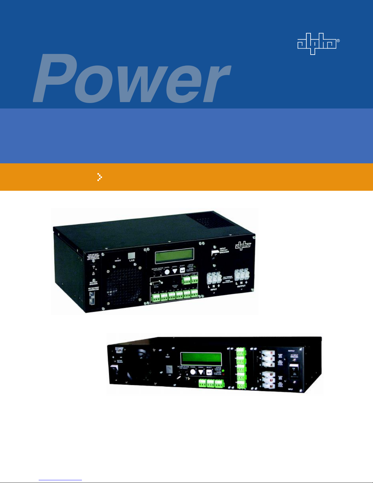
FXM UPS Operator's Manual
Doc# 017-201-B0 Rev 0408


 Plus Startup manual")