Alpha Tri Power X33 TE User manual

Tri Power X33 TE
10-60 kVA UPS
Installation and Operation Manual

Tri Power X33 TE 10/20/30/40/60 kVA
I
CONTENTS
Preface...................................................................................................................... 1
Safety......................................................................................................................... 2
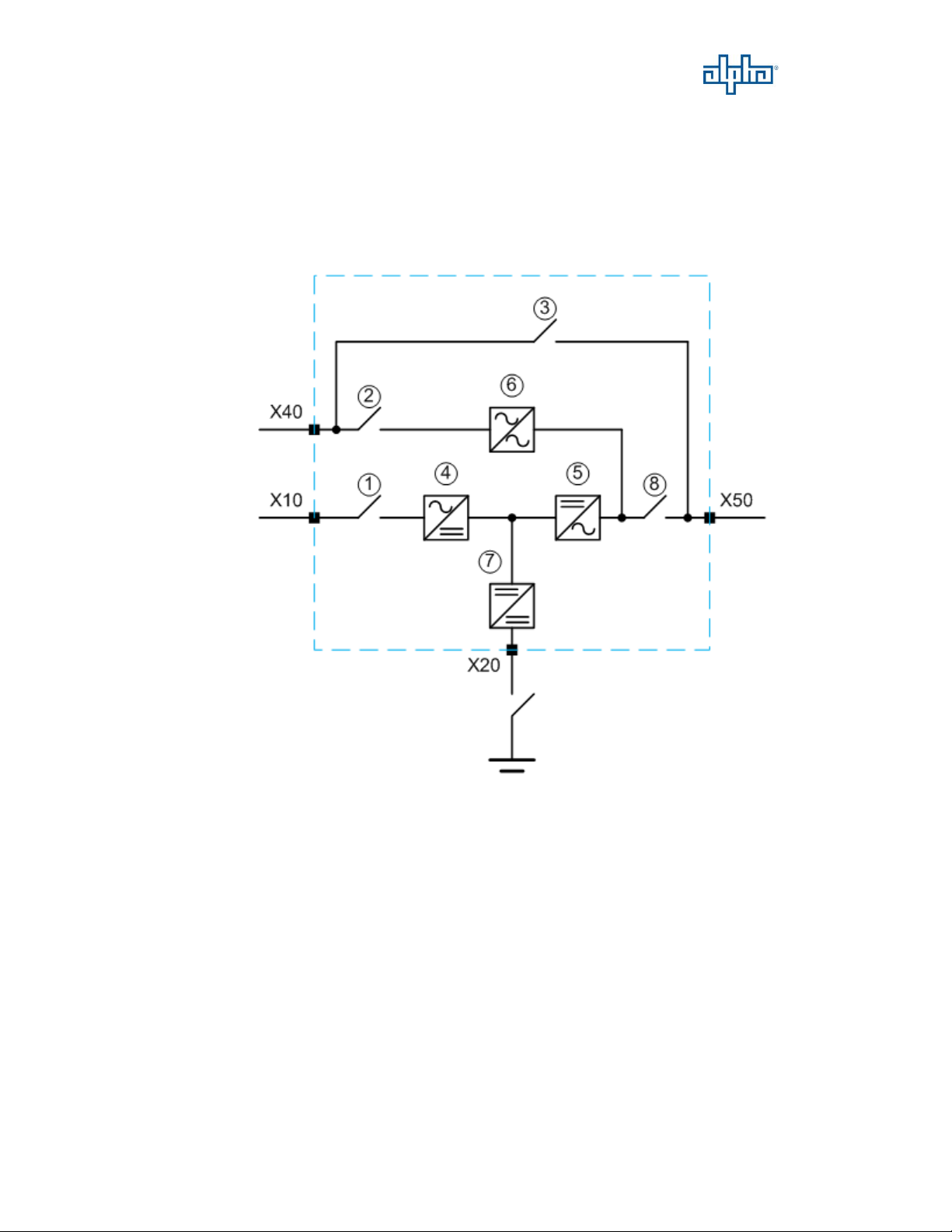
1. Function Description........................................................................................... 3
1-1. UPS Block Diagram........................................................................................ 3
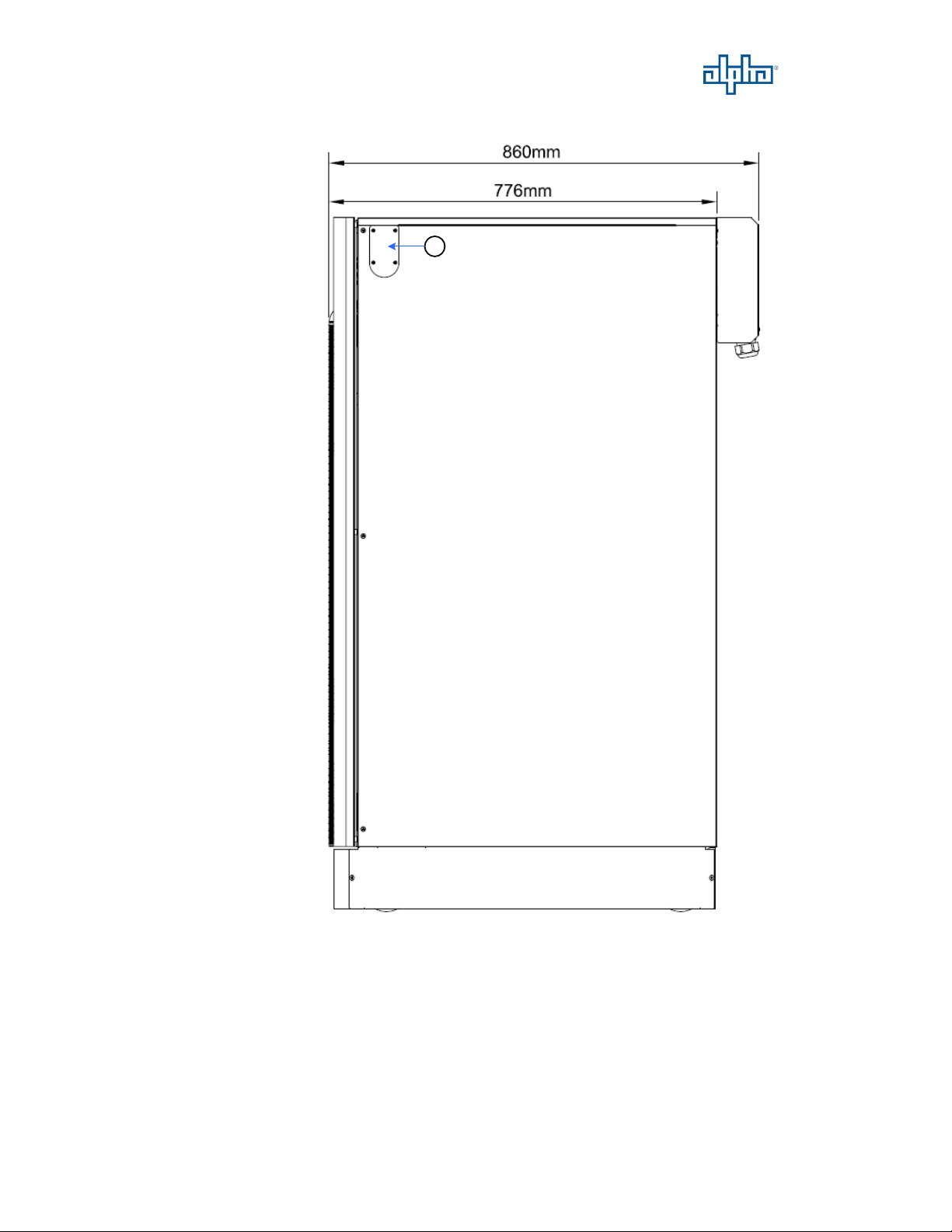
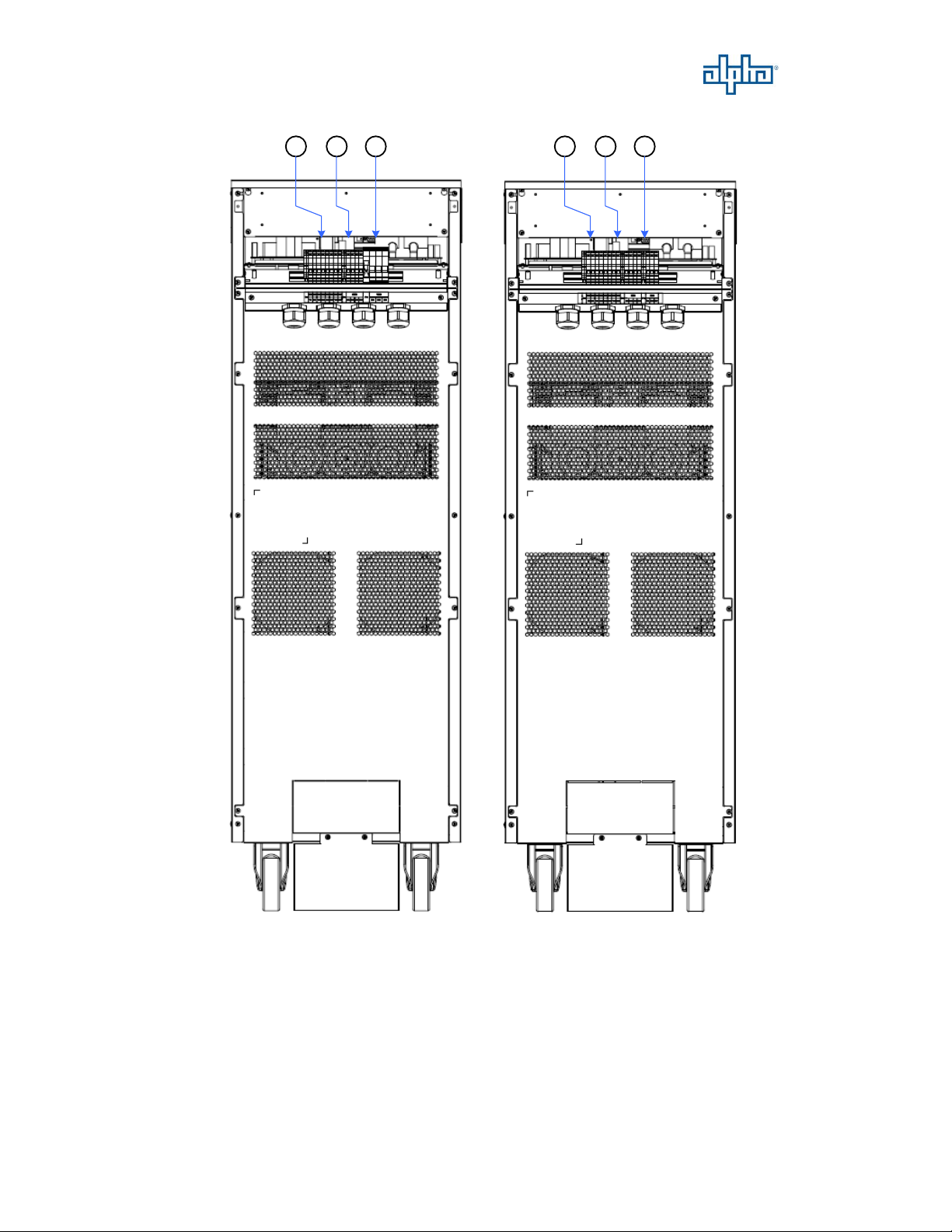
1-2. UPS Outlook View ......................................................................................... 4
2. Installation and Wiring..................................................................................... 15
2-1. Storage and Installation Environment ..........................................................15
2-2. Unpacking, Removing and Fixing UPS........................................................ 16
2-3. General Requirement for Ventilation and Maintenance...............................23
2-4. Power Cables Connections ........................................................................... 24
2-5. Communication Cables Connections............................................................ 33
2-6. UPS Parallel Connections............................................................................. 37
3. Operation Description.......................................................................................42
3-1. Operation Modes........................................................................................... 42
3-2. Online Operations......................................................................................... 43
3-3. Manual Bypass Operation............................................................................. 43
3-4. Operation Processes......................................................................................44
4. Control Panel Operation and Function Description......................................45
4-1. Screen Introduction.......................................................................................45
4-2. Menu .............................................................................................................46
4-3. Mimic Display .............................................................................................. 49

Tri Power X33 TE 10/20/30/40/60 kVA
II
5. Options................................................................................................................ 50
5-1. Dry Contact Card..........................................................................................50
5-2. RS-485 MODBUS Card ............................................................................... 50
5-3. SNMP Card...................................................................................................50
5-4. Temperature Sensor...................................................................................... 50
5-5. DC Cold Start Kit..........................................................................................51
5-6. Parallel Communication Cable.....................................................................51
6. Troubleshooting.................................................................................................52
7. Technical Specification ..................................................................................... 53

Tri Power X33 TE 10/20/30/40/60 kVA
1
Preface
We thank you for the trust in selecting our UPS.
Our equipment complies with the European Community directives for
professional equipment and is authorize to use the CE marking.
The purpose of this manual is to introduce the operating principles of the UPS and
to provide instructions for its safe operation. The manual also provides troubleshooting
assistance should an abnormal message or behavior occur.
Should an abnormal message not covered in this manual appear, please contact
your local authorized service agent for troubleshooting and repair.
All of the installation, operation, and maintenance of this device must be
performed by authorized and qualified technicians who are familiar with this manual.

Tri Power X33 TE 10/20/30/40/60 kVA
2
Safety
Important Rules
(1) Please follow these UPS operating instructions to ensure safe and proper operation.
(2) When the UPS is being moved or operated, please ensure that the machine is standing
vertically. Do not shake or tip over the machine. Avoid heavy impact.
(3) Poor grounding will lead to unexpected current leakage. Please ensure that the AC power
input is properly grounded (PE Ground) before making any connections.
(4) Please make sure that the UPS is placed in an insulated environment before use and that
there is no electrocution hazard to the operating personnel.
(5) Do not connect the neutral wire with the ground and make sure that the input voltage is
correct.
(6) Once the UPS has been switched on, if the UPS needs to be moved then it must be fully
switched off and fully discharged. If the UPS is not discharged, the UPS will switch to
battery power after grid power is disconnected and pose an electrocution hazard.
(7) Do not place any objects, liquid containers, or coverings over the UPS. The liquid spilt
into the UPS or heat prevented from dissipating could lead to internal damage or cause
electrocution.
(8) Make sure that the battery specifications match the UPS requirements before connecting
any external batteries.
(9) Please follow the rules below before engaging in any activity that involves the battery.
a. Remove all metallic items such as rings, watches and jewelry before working on
the battery.
b. Please use insulated tools.
c. Do not open or damage the battery. The toxic liquid inside will harm the skin and
eyes.
d. Keep batteries away from fire to prevent explosion.
Symbols
Please follow the instructions and warnings on the UPS.
WARNING!Refer to the operating instructions.
WARNING!High voltage inside.
Ground

Tri Power X33 TE 10/20/30/40/60 kVA
3
1. Function Description
1-1 UPS Block Diagram
This UPS provides Mains input and Bypass input for dual inputs application.
The system block diagram as shown below.
1.
Input Switch
5.
Inverter
2.
Bypass Switch
6.
Static Switch
3.
Manual Bypass Switch
7.
Charger/Booster
4.
Rectifier
8.
Output Switch
Load
Bypass Input
Mains Input
Battery
Input

Tri Power X33 TE 10/20/30/40/60 kVA
4
1-2 UPS Outlook View
10-40kVA Front View
1
2
4
3
440mm
1390mm
1.
Control Panel with Colorful LCD Touch Screen
3.
Ventilation Grille
2.
Handle with Lock
4.
Wheels for Handling

Tri Power X33 TE 10/20/30/40/60 kVA
5
10-20kVA Right Side View
1
1.
Through Hole for Parallel Communication Cable

Tri Power X33 TE 10/20/30/40/60 kVA
6
10-20kVA Internal View
1 2
3 4 5 6 7 8
1.
Parallel Communication Ports
2.
HMI Communication Port
3.
Communication Selector for
Service only
4.
USB Port for Service Only
5.
Terminal Resistor Setting Switch
for Parallel Communication
6.
Status LED Indictors
7.
EPO
8.
Backfeed Protection
9.
Communication Card Slot2
10.
Communication Card Slot1
Please find the detail descriptions of
above items on section 2-5.
11.
Mains Input Switch
14.
Output Switch
12.
Bypass Input Switch
15.
Fuse for Control Power
13.
Manual Bypass Switch
16.
Battery Tray
910
11
13
14
12
15
16

Tri Power X33 TE 10/20/30/40/60 kVA
7
10-20kVA Rear View
1 2 3 1 2 3
10kVA 20kVA
1.
X10/ X40: Mains/ Bypass Input
Connections Terminal
(1N, 2N, 1L3, 2L3, 1L2, 2L2, 1L1, 2L1)
2.
X50: Output Connections Terminal
(3N, 3L3, 3L2, 3L1)
3.
X20: External Battery Connections
Terminal (B+, N, B-)

Tri Power X33 TE 10/20/30/40/60 kVA
8
30-40kVA Right Side View
1
1.
Through Hole for Parallel Communication Cable

Tri Power X33 TE 10/20/30/40/60 kVA
9
30-40kVA Interval View
9
11
13
14
12
10
15
16
1 2
3 4 5 6 7 8
1.
Parallel Communication Ports
2.
HMI Communication Port
3.
Communication Selector for
Service Only
4.
USB Port for Service Only
5.
Terminal Resistor Setting Switch
for Parallel Communication
6.
Status LED Indictors
7.
EPO
8.
Backfeed Protection
9.
Communication Card Slot2
10.
Communication Card Slot1
Please find the detail descriptions of
above items on section 2-5.
11.
Mains Input Switch
14.
Output Switch
12.
Bypass Input Switch
15.
Fuses for Control Power
13.
Manual Bypass Switch
16.
Battery Tray

Tri Power X33 TE 10/20/30/40/60 kVA
10
30-40kVA Rear View
3
1
23
1
2
30kVA 40kVA
1.
X10/ X40: Mains/ Bypass Input Connections
Terminal
(1N, 2N, 1L3, 2L3, 1L2, 2L2, 1L1, 2L1)
2.
X50: Output Connections Terminal
(3N, 3L3, 3L2, 3L1)
3.
X20: External Battery Connections
Terminal (B+, N, B-)

Tri Power X33 TE 10/20/30/40/60 kVA
11
60kVA Front View
2
3
1
2
3
1
159mm
1253mm
251mm
1345mm
600mm
600mm
4
161mm
無無無 無無無
1.
Control Panel with Colorful LCD Touch Screen
3.
Ventilation Grille
2.
Handle with Lock
4.
Wheels for Handling
Wheel Type
Stationary Type
(Without Wheel)

Tri Power X33 TE 10/20/30/40/60 kVA
12
60kVA Left Side View
1.
Through Hole for Parallel Communication Cable
1.
1.
Stationary Type
(Without Wheel)
Wheel Type

Tri Power X33 TE 10/20/30/40/60 kVA
13
60kVA Internal View
11.
Mains Input Switch
16.
X20: External Battery Connection Terminals (B+, N, B-, G)
12.
Output Switch
17.
X10/ X40: Mains/ Bypass Input Connections Terminal
(1N, 2N, 1L3, 2L3, 1L2, 2L2, 1L1, 2L1)
13.
Bypass Input Switch
18.
X50: Output Connection Terminals (3N, 3L3, 3L2, 3L1)
14.
Manual Bypass Switch
15.
Fuses for Control Power
1.
Parallel Communication Ports
2.
HMI Communication Port
3.
Communication Selector for
Service Only
4.
USB Port for Service Only
5.
Terminal Resistor Setting Switch
for Parallel Communication
6.
Status LED Indictors
7.
EPO
8.
Backfeed Protection
9.
Communication Card Slot2
10.
Communication Card Slot1
Please find the detail descriptions of
above items on section 2-5.
1.
2.
○,2
3.
4. 6.
5.
7.
8.
9.
10.
11.
○,11
12.
13.
14.
○,14
16.
○,16
17.
18.
15.

Tri Power X33 TE 10/20/30/40/60 kVA
14
Rear Side of Front Door View
1.
USB Port for Setting Software
4.
Output & Input Contacts
2.
SD Card Slot
5.
RS-232 Port for Setting Software
3.
External Battery Temperature Connector
6.
Communication Port for Remote
Panel
Please find the detail descriptions of above items on section 2-5.
4.
○,4
5.
1.
2.
3.
6.
○,6

Tri Power X33 TE 10/20/30/40/60 kVA
15
2. Installation and Wiring
2-1 Storage and Installation Environment
Storage Environment
Temperature -20℃~70℃
Relative Humidity ≦95%
Installation Environment
A proper installation environment not only ensures the effective operation of the
UPS but also reduces the chance of failure and extends service life. Please take the
following recommendations into account to select the most suitable environment and
reduce the likelihood of accidents.
Temperature 0℃~40℃(20℃~25℃is recommended for extend batteries life
time).
Relative Humidity ≦95% (without condensation)
Altitude 1000m at normal power. Over 1000m above sea level, the maximum
output current must be derated by 1% every additional 100m.
This product must not be used in an environment with sparks, smoke or gas
to prevent arcing, injury and fire hazards.
Avoid using dusty materials, volatile gases, or corrosive substances with a
high salt-content in the environment where the UPS is installed.
The installation location of the UPS should be well-ventilated. During
charging, the chemical reaction of the battery generates small amounts of
gases. If there is a crack in the battery then this may pose an environmental
hazard.
Do not place in a location near a heat source as this will shorten the battery
life.
Do not place outdoors and avoid direct exposure to sunlight.
Please ensure that the environment where the UPS is placed is free from
animals that may damage the wiring, such as: rats and other small animals.
Please ensure that the floor is strong enough to hold the UPS and battery. It
must keep the equipment stable to ensure that it won't suffer damage in a fall.
We recommend placing a fire extinguisher near the UPS in case of an
emergency.

Tri Power X33 TE 10/20/30/40/60 kVA
16
2-2 Unpacking, Removing and Fixing UPS
This section describes the unpacking and removing processes for wheel type.
Remove the packing materials and cut straps. Remove the cardboard box.
10-40kVA 60kVA
Unscrew the fastening rail kits on the front and rear side of 10-40kVA, and right
and left side of 60kVA.
10-40kVA 60kVA

Tri Power X33 TE 10/20/30/40/60 kVA
17
Put 2 fastening rail kits on the pallet edge and make them steady by fastening 4
screws in the pallet.
10-40kVA
60kVA
Table of contents
Other Alpha UPS manuals

Alpha
Alpha Novus FXM 650 User manual

Alpha
Alpha Novus FXM 650 User manual

Alpha
Alpha Novus FXM 650 User manual

Alpha
Alpha Novus FXM 1100 User manual

Alpha
Alpha Pinnacle Plus Series User manual

Alpha
Alpha XM2-300HP User manual

Alpha
Alpha XM3-HP Series User manual

Alpha
Alpha FXM HP User manual

Alpha
Alpha CFR 5000 User manual

Alpha
Alpha FlexPoint FPR1207-F User manual