Alpha Novus FXM 1100 User manual

Alpha Technologies
www.alpha.com
Operator’s Manual
017-201-B0 Rev 05/07
Novus FXM 650/1100/2000
Uninterruptible Power Supply

Power
Alpha Technologies
®

Uninterruptible Power Supplies
Alpha Technologies
www.alpha.com
017-201-B0 Rev. 02/ 07
Operator’s Manual
Novus FXM 650/1100/2000
FXM 650
FXM 1100/2000

Save This Manual: It contains important installation and operating instructions. Keep it in a safe place.
Table of Contents
The emergency shutdown procedure is on the inside rear cover
DANGER
Risk of Electrical Shock
To reduce the risk of electrical shock and to ensure the safe operation of the Novus FXM UPS, the fol-
lowing symbols are used throughout this manual. Where they appear, only qualied personnel should
carry out these instructions.
A dangerous voltage exists in this area. Use extreme caution at all times.
Attention: Important operating instructions. Follow them exactly.
1 Introduction................................................. 1
1.1 Safety Checklists ................................... 2
1.1.1 UPS Safety Checklist..................... 2
1.1.2 Battery Safety Checklist................. 3
1.2 Unpacking and Inspection Checklist ...... 4
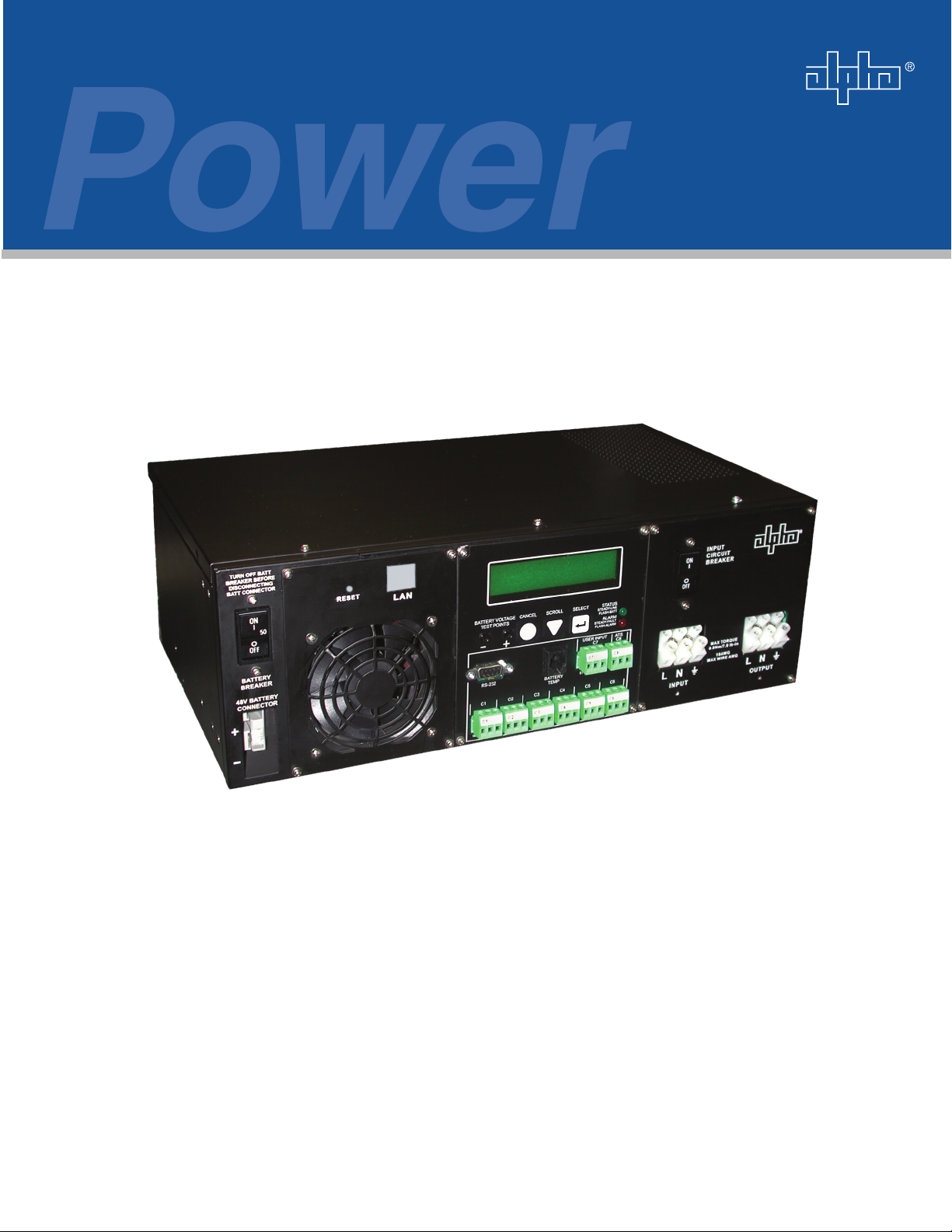
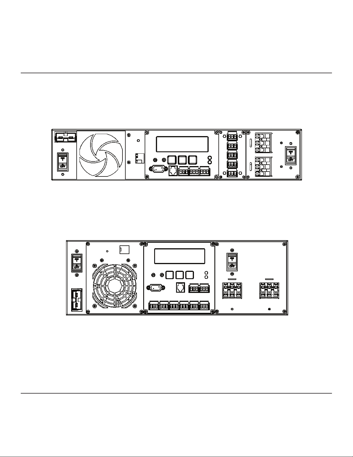
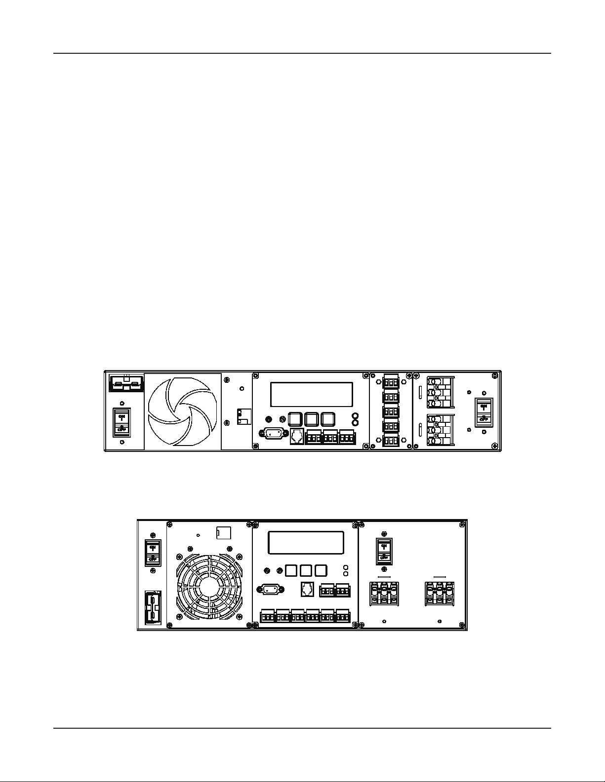
1.3 The FXM Front Panel............................. 5
2 Installation................................................. 11
2.1 Site Preparation Checklists .................. 12
2.2 Mounting the UPS ............................... 13
2.3 Wiring the External Batteries ............... 14
2.4 Wiring the UPS.................................... 16
2.5 ATS/GTS Option .................................. 17
3 Operation................................................... 18
3.1 Operating the Control Panel................. 19
3.2 Turning the UPS On and Off................ 21
3.3 Replacing the Batteries........................ 23
3.4 Operating the UPS .............................. 24
3.5 Making Measurements ........................ 26
3.6 Troubleshooting the UPS..................... 28
3.7 Viewing the 25-Event Log.................... 30
4 Communication ........................................ 31
4.1 Wiring the RS-232 Port ........................ 32
4.2 Using the Main Menu........................... 33
4.2.1 Main Menu Screen....................... 33
4.2.2 RS-232 Menu Tree....................... 34
4.2.3 Line Status................................... 35
4.2.4 Output Status............................... 35
4.2.5 Fault and Alarm Displays ............. 36
4.3 Adjusting and Controlling the UPS....... 37
4.4 Programming the Dry Contacts and the
Clock ..................................................... 38
4.4.1 Programming the Dry Contacts ... 38
4.4.2 Setting the Timer Contact ............ 39
4.4.3 Setting the Date and Time ........... 39
4.5 100-Event Log ..................................... 40
4.6 Novus User Software........................... 41
4.6.1 Introduction .................................. 41
4.6.2 Checking Your Windows Computer
for the .NET Framework............... 41
4.6.3 Installation and Set Up................. 42
4.6.4 Operation ..................................... 43
5 Maintenance.............................................. 46
5.1 Updating the Software ......................... 47
Specications .............................................. 49
Index ............................................................. 51
Warrant ......................................................... 54

1
Introduction
This Section Introduces the Novus FXM Uninterruptible Power Supply (UPS)
Safety Instructions (Section 1.1)•
Unpacking and Inspection Instructions (Section 1.2)•
A Description of the FXM 650 and FXM 1100/2000 Front Panels (Section 1.3)•
1
1 Introduction

1.1.1 UPS Safety Checklist
This Uninterruptible Power Supply (UPS) must be installed in a restricted access
location, and by trained personnel qualied in the safe use of high-energy power
supplies and their batteries. Also assumed is knowledge of the local electrical code(s)
and their safe application.
This Uninterruptible Power Supply (UPS) is suitable for installation as part of the
Common Bonding Network (CBN) as dened in GR-1089-CORE.
DANGER: NEVER let water from rain, a hose, tap or a sprinkler’s output, road
splash or other water sources enter the UPS to prevent accidental shorts, shocks or
electrocutions.
Do not work alone under hazardous conditions.F
Read this manual. If you have any questions about safe installation, operation orF
maintenance, contact Alpha Technologies’s customer service department.
Carefully unpack the components. Report any shipping or other damage at once.F
AlwaysFassume electrical connections or conductors are live. Turn off all circuit breakers
and double-check with a voltmeter before performing installation or maintenance.
Before installation, verify the input voltage and current requirements of the load are met byF
the UPS’s output (See specications). Verify the line voltage and current meet the UPS’s
input requirements.
Place a warning label on the utility panel to tell emergency personnel a UPS is installed.F
Use proper lifting techniques when lifting or moving the UPS or its components.F
This UPS has more than one live circuit. AC power may be present at the outputs even ifF
the UPS is disconnected from line or battery power.
This UPS can be operated to a maximumFoperating temperature of 55°C except for the
FXM 2000–120VAC unit which has a maximum temperature rating of 50°C. Also see the
specications section for temperature ratings and deratings.
At high ambient temperature conditions, the UPS’s surface can be very hot to the touch.F
There is aFLithium battery inside the UPS. There is a danger of an explosion if it is
incorrectly replaced. Replace it only with the same type or an equivalent battery as
recommended by the manufacturer. Dispose of the old battery as instructed by the
manufacturer.
1.1 Safety Checklists
1.1.1 UPS Safety Checklist
2
FXM UPS Operator's Manual
Doc# 017-201-B0 Rev 05/07

1.1.2 Battery Safety Checklist
Battery Emergency Procedures
If electrolyte splashes on your skin, immediately wash the affected area with water. If
electrolyte gets into your eyes, wash them for at least 10 minutes with clean running
water or a special neutralizing eye wash solution. Seek medical attention at once.
Neutralize spilled electrolyte with special neutralizing solutions in a “spill kit” or a
solution of 1 lb. (0.45 kg) of baking soda (bicarbonate of soda) in 1 gallon (3.9 L.) of
water.
Battery installation and servicing should be done or supervised by personnelF
knowledgeable about batteries and the required precautions.
CAUTION:FRisk of explosion if battery is replaced by an incorrect type. Always replace the
battery with the same type, numbers, and ratings.
CAUTION:FNever install old or untested batteries. One sealed lead-acid battery is rated to a
maximum voltage of 12VDC.
CAUTION:FNever dispose of batteries in a re. The batteries may explode. Follow the
manufacturer’s directions for safe battery disposal.
CAUTION:FNever open or damage the batteries. Released electrolyte is harmful to the skin
and eyes. It may be toxic and hazardous to the environment.
CAUTION:FA battery can present a risk of electrical shock and high short-circuit current.
The following precautions should be observed when working on batteries:
Remove watches, rings, or other metal objects.•
Use tools with insulated handles.•
Wear rubber gloves and boots.•
Do not lay tools or metal parts on top of batteries.•
Disconnect charging source prior to connecting or disconnecting battery terminals.•
Determine if the battery is inadvertently grounded. If inadvertently grounded, remove•
source from ground. Contact with any part of a grounded battery can result in
electrical shock. The likelihood of such shock can be reduced if such grounds are
removed during installation and maintenance (applicable to equipment and remote
battery supplies not having a grounded supply circuit).
CAUTION:FNever let live battery wires touch the UPS, the enclosure or any other metal
objects. This can cause a re or explosion.
Lead-acid batteries can release Hydrogen gas. Never expose the UPS or enclosure to openF
ames or sparks to prevent a re or explosion.
Inspect the batteries once a year for signs of cracks, leaks or swells. Replace as needed.F
If you have batteries in storage, charge them at least once every three months for optimumF
performance and to extend their lifetime.
1.1.2 Battery Safety Checklist
3
Introduction
Doc# 017-201-B0 Rev 05/07

If items are missing or damaged, contact Alpha Technologies and the shipping company
at once. Most shippers have a short claim period.
Carefully remove the UPS from the shipping container. Inspect the contents and make sure the
following items are included:
1 Novus FXM UPS.F
1 Novus FXM UPS Operator’s Manual.F
8 terminal blocks and labels for the dry contacts.F
1 temperature sensor cable.F
Any ordered options.F
If ordered from Alpha, the batteries will be shipped separately.
Save The Shipping Container
To return the Novus FXM for servicing, pack it in the shipping container. Alpha Technologies is
not responsible for damage caused by improper packaging of returned units.
Save These Instructions
This manual contains important instructions for the Novus FXM series of UPS that shall be
followed during installation and maintenance. You must read and understand the procedures
and drawings in this manual before operating the unit. If you have any questions about the
safe installation, operation or maintenance of this UPS, contact Alpha’s customer service
department (www.alpha.com).
1.2 Unpacking and Inspection Checklist
4
FXM UPS Operator's Manual
Doc# 017-201-B0 Rev 05/07

1.3 The FXM Front Panel
The FXM UPS is available in 3 models – FXM 650, FXM 1100 and FXM 2000. The FXM 650
and the FXM 1100/2000 look different, but all of the front panel connectors and circuit breakers
operate in the same way. However the circuit breakers for each unit have different ratings. See
the specications section for details. All units operate in the same way unless stated otherwise
in this manual.
The FXM 650 is available in two versions:
FXM 650-24VDC – with a 24 VDC battery string voltage•
FXM 650-48VDC – with a 48 VDC battery string voltage•
The FXM 1100 is available in only one version:
FXM 1100-48VDC – with a 48 VDC battery string voltage•
The FXM 2000 is available in only one version:
FXM 2000-48VDC – with a 48 VDC battery string voltage•
1.3 The FXM Front Panel
Figure 1.3.2
Novus FXM 1100/2000 Front Panel
Figure 1.3.1
Novus FXM 650 Front Panel
5
Introduction
Doc# 017-201-B0 Rev 05/07

1Battery Breaker
This circuit breaker provides overcurrent protection and is an on/off switch for battery
power. It must be on for proper UPS operation.
2Battery Connector
This connects the external batteries to the UPS.
3Internal Fan
This microprocessor-controlled fan regulates the UPS’s internal temperature for optimum
performance. It must not be blocked.
If the fan fails, an Alarm is generated (See Section 3.6, “Troubleshooting”).•
4LAN
This optional RJ-45 connector is the UPS’s Ethernet connector.
1
2
3
4
1
24
6
FXM UPS Operator's Manual
Doc# 017-201-B0 Rev 05/07

5LCD Control Panel
This panel and the cancel, scroll and select buttons below it let you monitor and control the
UPS. More information is given in Section 3, “Operation.”
6Battery Voltage Test Points
These let you measure the battery voltage. They accept 2 mm diameter test probe tips.
The battery circuit breaker must be on to measure the voltage.
NOTE: It is not and should not be used as a power outlet.•
7RS-232
This DE-9 connector allows you to use a straight-through DB-9 to DE-9 connector
computer cable to connect the UPS to a computer for remote control and monitoring. More
information is given in Section 4, “Communication.”
8Battery Temp
This connector attaches the battery temperature sensor to the UPS so the UPS can
monitor the battery temperature. The charging voltage is temperature dependant and the
UPS’s microprocessor adjusts it for optimum charging.
The sensor• MUST be attached to the UPS for normal operation. Firmly attach the sensor end to the
centre battery’s case with high-strength ameproof tape (such as duct tape) as shown in Section 2.3,
“Wiring the External Batteries.” If it isn’t, a “Temperature Probe Unplugged” alarm will appear on the
LCD. See Section 3.6, “Troubleshooting,” “Temp Probe Unplugged.”
6
78
FXM650
10 C6 11
9
5
FXM1100/2000
5
6
7
89
11
10
7
Introduction
Doc# 017-201-B0 Rev 05/07

9Contacts C1 to C6
Contacts C1 to C5 allow you to connect the UPS to an external monitoring panel or to
trafc control equipment.
The factory default settings are as given below, but you can program them to meet your
requirements (See Section 4.4, “Programming the Dry Contacts and the Clock”). To learn
how the contacts are congured, see Section 4.4.1, “Programming the Dry Contacts” or
Section 4.6, “Novus User Software.”
For Contact C6, the default factory conguration for the FXM 1100/2000 is +48VDC output
(FXM 650-24 is +24VDC, FXM 650-48 is +48VDC), but it can be factory congured as a
dry contact.
Figure 1.3.3A shows the contact’s layout while Figure 1.3.3B shows the +48VDC or
+24VDC terminal block layout.
C1:• This contact is energized when line power is unqualied and the UPS provides backup battery
power to the load(s). It can be called the “On Battery” contact.
C2, C3:• These contacts are energized when the battery drops below a pre-set voltage level. They can
be called the “Low Battery” contacts.
You can change the pre-programmed level to match the batteries used and the actual operating
conditions. See Section 4.3, “Operating the UPS, “#35 Low Battery Warning Voltage.”
C4:• This contact is energized after the UPS has been in Inverter mode for 2 hours. It can be called
the “Timer” contact.
You can change the pre-programmed 2 hours to match your operating conditions. See Section 4.4.2,
“Programming the Dry Contacts and the Clock, Setting the Timer Contact.”
C5:• This contact is energized when the UPS has a malfunction. It can be called the “Alarm” contact.
C6:• The factory default layout for this contact is a relay that is energized when the UPS is in Line
or Inverter modes and is de-energized when it is in Standby mode. It provides 48VDC (500 mA) or
24VDC (500 mA) from the external batteries to an external fan or other equipment. C6 can be factory-
congured as a dry contact.
Figure 1.3.3A
Contact Layout
(Standard for C1 to C5, Factory Option for C6)
Figure 1.3.3B
48VDC/24VDC Contact Layout
(De-energized Shown, Factory Default for C6)
The contacts have
a maximum rating
of 1A at 250V.
+48VDC, 500mA
(FXM 1100/2000, 650-
48) or +24VDC (FXM
650-24) from the
external batteries.
Microprocessor
18
16 17
+
Contact
C6
Microprocessor
UPS
Interior
Normally
Closed (NC)
Normally
Open (NO)
Common(C)
8
FXM UPS Operator's Manual
Doc# 017-201-B0 Rev 05/07

10 Contacts C7 and C8
These optically isolated inputs let you attach an external switch panel for remote control of
the UPS or have the UPS control Alpha Technologies’s optional Automatic Transfer Switch
(ATS).
User Input (C7):• This relay has 3 contacts to control the UPS (Figure 1.3.4A). They are:
19 (S1): Shorting this contact starts the UPS’s self test. Also see Section 3.4, “Operating the UPS,
Battery Test.”
20 (S2): Shorting this contact activates an alarm. Also see Section 3.6, “Troubleshooting, User
Input Alarm.”
21 (S3): Shorting this contact shuts off the UPS.
22 (C): Isolated return for contacts S1, S2 and S3. It is located on contact C8 (#22).
ATS (C8):• When the UPS is in Inverter mode, this normally open relay closes (Figure 1.3.4B),
sending 48VDC (FXM 1100/2000) or 24VDC (FXM 650) from the external batteries to this dry contact.
If the optional Alpha Technologies’s Automatic Transfer Switch (ATS) is connected, this causes the
ATS to switch the load from line power to the UPS’s battery backup power.
11 Status and Alarm LEDs
Status:• When this green LED is on, the UPS is in Line mode and line power is provided to the load.
When it is ashing, it is in Inverter mode and backup battery power is provided to the load.
Alarm:• When this red LED is on, the UPS has a fault. When it is ashing, it has an alarm (See
Section 3.6, “Troubleshooting”).
48VDC or 24VDC from
the external batteries
Figure 1.3.4A
User Input Layout
Figure 1.3.4B
ATS Layout
Contact C7 Contact C8 Contact C8
Microprocessor
23 24
+
19
S1:Self Test
20
S2:Alarm
21
S3:Shutdown
22
Common
9
Introduction
Doc# 017-201-B0 Rev 05/07

12 Input Circuit Breaker
This circuit breaker is an on/off switch for line power into the UPS and provides input
protection. It must be on for proper UPS operation.
13 Input
This terminal block is the UPS’s power input.
14 Output
This terminal block is the UPS’s power output.
12
14
13
13 14
12
10
FXM UPS Operator's Manual
Doc# 017-201-B0 Rev 05/07

11
Installation
This Section Tells You How to Install and Wire the Novus FXM UPS
Site Preparation Checklist (Section 2.1)•
Mounting the UPS (Section 2.2)•
Wiring the External Batteries (Section 2.3)•
Wiring the UPS to the Line and the Load (Section 2.4)•
ATS/GTS Option (Section 2.5)•
2

2.1 Site Preparation Checklist
FGrounding
The UPS MUST be correctly grounded for proper operation.
Older facilities may have inadequate electrical grounding. Inspection must be performed
by a qualied electrician before installation to ensure that grounding meets the local
electrical code.
FBranch Circuit Breaker Protection
To provide branch circuit protection, the utility line attached to the UPS’s input
MUST be protected by a circuit breaker certied for this use in accordance with
the local electrical code.
The breaker’s minimum size is calculated by the following formula:
Minimum Breaker Size= UPS’s maximum input current / 0.8
The UPS’s maximum input current is read off of the UPS’s nameplate. For example, if
the nameplate gives the maximum input current as 20A, the circuit breaker should be
rated at least 25A.
For the FXM 1100, to reduce the risk of re, connect to a 20 A (for 120 V units) or
10 A (for 230 V units) maximum branch circuit overcurrent protection.
FDisconnects
The input and output lines to and from the UPS MUST have disconnect devices
attached.
Site RequirementsF
Install the UPS and batteries in a restricted access location, and on a surface that supports
the total weight. The input wiring must reach a suitably grounded power outlet and the load
wiring must reach the UPS’s output terminal blocks.
FBackup Generator (If used)
In Generator Mode, the UPS’s range of acceptable input frequency and voltage is
expanded to accept the uctuations created by a generator (See Section 3.4, “Operating
the UPS, Sense Type”).
Use a generator with electronic speed and voltage controls which produces less than 10%
voltage Total Harmonic Distortion (THD). Mechanical governors can force the UPS to run
continuously in Battery mode.
Before installation, make sure the generator’s output voltage is compatible with the UPS’s
input voltage requirements. To make sure the system runs smoothly, use a generator that
supplies twice as much power as drawn by the total load.
12
FXM UPS Operator's Manual
Doc# 017-201-B0 Rev 05/07

2.2 Mounting the UPS
The UPS can be placed on a shelf with no other parts needed. Any version of the FXM can be
rack or wall mounted or secured to a shelf, such as on an outdoor enclosure’s shelf, with the
optional mounting brackets as shown in Figure 2.2.1. The brackets and the screws to attach
them to the UPS’s case are available from Alpha Technologies (part number 740-697-21).
Terminal block covers and the battery harness restraining bracket MUST be
used and are available from Alpha Technologies (part number 740-698-21). If the
UPS end application is mounted inside an enclosure or in an area restricted to
authorized personnel, then the covers and bracket may or may not be needed.
For the FXM 1100/2000 units only, the control panel and the power
connection panel can be rotated to suit your needs. To rotate either
one, unscrew the screws in each corner, remove the panel, rotate it
and reinstall the screws.
Use care to avoid damaging or pulling out the wires or
the ribbon cables when rotating the panels.
NOTE: To meet NEBS Level 1 specications when you are installing this unit in a
rack or frame, you MUST:
Before installation, clean all attachment points on the UPS, rack and mounting brackets1.
and bring them to a bright nish. Then coat them with an anti-oxidant (such as Sanchem
Inc.’s No-Ox ID “A-Special Electrical Grade” or equivalent).
Attach the mounting brackets with the provided screws insure adequate grounding2.
between the UPS’s chassis and the rack or frame.
Figure 2.2.1 – Mounting the UPS
Mounting brackets position for rack mounting (rotate to t either 19-inch or 23-inch racks).
13
Installation
Doc# 017-201-B0 Rev 05/07

2.3 Wiring the External Batteries
DANGER: Before starting, make sure you have read the instructions on battery
safety in Section 1.1 of this manual.
Tools and Materials Required
• DC Voltmeter.
• Labels or masking tape and marker.
• Torque wrench.
• High strength, ame-proof tape (such as duct tape).
• Battery terminal corrosion inhibitor (such as NOCO Company’s NCP-2 or Sanchem Inc.’s
No-Ox ID Grease “A”).
• If ordered from Alpha, battery cable connector kit or kits.
Battery Checklist
Use new batteries when installing a new unit. Verify they are all the same battery type withF
identical date codes.
For the FXM 650, the battery string is 24VDC. For the FXM 1100/2000, the battery string isF
48VDC.
Before attaching the batteries to the UPS, make sure the polarity is correct.F
If you are making your own batteryFwiring harness, use at least 10 AWG (for FXM 650/1100)
or 8 AWG (FXM 2000).
The battery return connection is to be treated as an Isolated DC return (DC-I) as dened in F
GR-1089-CORE.
If batteries have been in storage for more than 3 months, recharge them for at least 24F
hours then test them with a load before installation.
EachFAlphaCell™ battery has a date code, found on the warning label, which must be
recorded in the maintenance log. If non-Alpha batteries are used, see the manufacturer’s
documentation for date code type and placement.
14
FXM UPS Operator's Manual
Doc# 017-201-B0 Rev 05/07

Procedure
1. For FXM 1100/2000 and FXM 650-48 (48 V battery string), number the batteries from 1
to 4 with labels or tape as shown in Figure 2.3.1a. For FXM 650-24 (24 V battery string),
number the batteries from 1 to 2 as shown in Figure 2.3.1b.
2. Coat the battery terminals with battery corrosion inhibitor.
3. Wire the batteries as shown in Figure 2.3.1a (for 48 V battery string) or Figure 2.3.1b (for
24 V battery string). If used, install the in-line fuse as shown.
Torque the battery terminals according to the manufacturer’s specications as
given on the name plate or data sheet.
4. Verify the battery connector polarity and DC voltage with a voltmeter. If correct, attach it to
the UPS’s external battery connector. If not, perform troubleshooting before connecting it
to the UPS.
5. Route the sensor end of the battery temperature cable to the batteries. Tape it to the side
of the battery as shown in Figure 2.3.1a or Figure 2.3.1b.
6. If multiple battery strings are used, repeat steps 1 to 4 above as required.
Battery Wiring Finished
Figure 2.3.1a
External Battery Wiring (for 48 V battery string)
– +
Battery #1
– +
Battery #2
– +
Battery #3
– +
Battery #4
Tape the battery temperature sensor to the side of either battery #2 or battery #3.
Optional In-Line Fuse
To negative (–) terminal To positive (+) terminal
Figure 2.3.1b
External Battery Wiring (for 24 V battery string)
Tape the battery temperature sensor to the side of either battery #1 or battery #2.
– +
Battery #1
– +
Battery #2
Optional In-Line Fuse
To negative (–) terminal To positive (+) terminal
15
Installation
Doc# 017-201-B0 Rev 05/07

DANGER: Before starting, make sure line power is turned off and that the UPS’s
battery and input circuit breakers are turned off.
If stranded wires are used to connect the input and output terminal blocks, ferules
or equivalent crimping terminals must be used.
Tools and Materials Required
• Slot head screwdriver to t the terminal blocks.
• Maximum 12 AWG copper wire rated to at least 90°C for the input and output power
terminal blocks (or as specied by the local electrical code).
• If the contacts are used, a maximum of 16 AWG should be used for wiring.
Procedure
1. Connect the battery temperature sensor
to the UPS. The sensor end of the cable
should be attached to the side of the
centre battery as shown in Figure 2.3.1a
or b.
2. If used, connect:
• The Ethernet port.
• The RS-232 port.
• The contacts.
• The user inputs.
3. Connect the load line to the UPS’s output
terminal block.
4. Connect the line power line to the UPS’s
input terminal block.
2.4 Wiring the UPS
Temperature sensor
connector
Ethernet port
Contacts User inputs
RS-232
port
Input terminal block
Output terminal block
FXM650
Output terminal block
Input terminal block
FXM 1100–2000
16
FXM UPS Operator's Manual
Doc# 017-201-B0 Rev 05/07
Other manuals for Novus FXM 1100
1
Table of contents
Other Alpha UPS manuals

Alpha
Alpha XM2-300HP User manual

Alpha
Alpha CFR 5000 User manual

Alpha
Alpha Pinnacle Plus Series User manual

Alpha
Alpha Tri Power X33 TE User manual

Alpha
Alpha Novus FXM 650 User manual

Alpha
Alpha Novus FXM 650 User manual

Alpha
Alpha FXM HP User manual

Alpha
Alpha FlexPoint FPR1207-F User manual

Alpha
Alpha Novus FXM 1100 User manual

Alpha
Alpha XM 6015 Series User manual