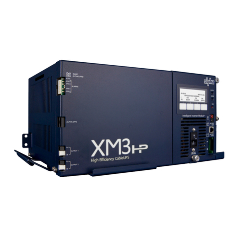
Alpha XM2-300HP User manual

XM2-300HP
Technical Manual
XM2-300HP
XM2-300CE-HP
Effective: September 2010
member of The Group™

Power
Alpha Technologies
®

Contacting Alpha Technologies: www.alpha.com
or
1-800-863-3930
For complete technical support, call
1-800-863-3364
7 AM to 5 PM, Pacic Time, or 24/7 emergency support
XM2-300HP Technical Manual
017-877-B1-001, Rev A
Effective Date: September 2010
Copyright© 2010
Alpha Technologies, Inc.
A member of The Alpha Group
Notice of FCC Compliance
Per FCC 47 CFR 15.21:
Per FCC 47 CFR 15.105:
to part 15 of the FCC Rules. These limits are designed to provide reasonable protection against harmful interference in a residential installation.
Reorient or relocate the receiving antenna.
3
Photographs contained in this manual are for illustrative purposes only. These photographs may not match
your installation.
or your nearest Alpha representative.
its intended purpose, or is installed or operated in an unapproved manner, or improperly maintained.
NOTE:
NOTE:
NOTE:

Table of Contents
Safety Notes ...................................................................................................................... 7
Battery Safety Notes.............................................................................................................8
............................................................................................9
Grounding and Earth Connection Notes.............................................................................11
....................................................... 12
1.1 Theory of Operation..................................................................................... 13
.......................................................................... 13
1.1.2 Standby Operation ............................................................................ 14
1.1.3 Charger Operation ............................................................................ 15
Charger Modes ................................................................................. 15
1.2 XM2-300HP Layout...................................................................................... 16
.......................................................... 16
................................................................. 17
1.2.3 Optional Status Monitoring Module.................................................. 19
1.3 Recommended Enclosure System Options ................................................. 20
........................... 20
................................................................ 20
........................................................................................ 20
.................................................................. 20
LA-P+ With Status Monitoring...................................................................... 20
................................................................................ 20
............................................. 20
2.0 Installation .......................................................................................................... 21
2.1 Installation Procedure .................................................................................. 22
.......................................... 23
2.3 Inverter Module Removal and Installation.................................................... 25
2.4 Protective Interface Module Installation (optional feature)........................... 26
2.5 Programming the PIM.................................................................................. 27
2.5.1 The Setup Menu................................................................................ 28
................................................................. 29
.......................................................................................................... 31
.................................................................... 31
............................................................. 31
4017-877-B1-001 Rev. A

4.0 Operation .......................................................................................................... 32
4.1 Start-up and Test.......................................................................................... 32
4.1.1 AC Line Operation............................................................................. 32
4.1.2 Self Test Operation............................................................................ 33
4.1.3 Standby Operation ........................................................................... 34
4.2 Using the Smart Display .............................................................................. 35
4.3 Smart Display modes for XM2-300HP......................................................... 37
4.3.1 Operation Normal.............................................................................. 37
........................................... 38
4.3.3 Setup Menu....................................................................................... 39
..... 42
............ 43
4.4 Alarm Indications ......................................................................................... 44
4.5 Control Panel LEDs........................................................................... 47
4.6 Smart Display Glossary ............................................................................... 48
4.7 Automatic Performance Test........................................................................ 50
.................................... 51
..................................................................................... 51
4.8.2 Using a Truck-mounted Inverter or Generator .................................. 52
......................................................................... 53
5.0 XM2-300HP Maintenance....................................................................................... 54
5.1 System Information...................................................................................... 54
............................................................................... 55
5.3 Battery Terminals and Connecting Wires..................................................... 55
............................................................................................. 55
5.5 Output Current ............................................................................................. 55
5.6 Check Output Connections.......................................................................... 55
............................................................................... 55
5.7 Inverter Module Maintenance ...................................................................... 56
5.8 Maintenance Log ......................................................................................... 57
6.0 Return and Repair Information ............................................................................... 58
.................................................................................. 59
.......................................................................................................... 60
7.1 Safety and EMC Compliance....................................................................... 61
Table of Contents, continued
5
017-877-B1-001 Rev. A
Table 4-1 AC Output ................................................................................................................................ 33
Table 4-2 Major Alarms............................................................................................................................ 45
Table 4-3 Minor Alarms............................................................................................................................ 46
............................................................................... 60
List of Figures and Tables
....................................................................................................... 13
......................................................................................................... 14
Fig. 1-3 Charger Modes ........................................................................................................................ 15
Fig. 1-4 Transformer Module Connections ............................................................................................ 16
Fig. 1-5 AC Input Connections and Product Label ................................................................................... 16
Fig. 1-6 Smart Display ........................................................................................................................... 17
Fig. 1-7 Inverter Module Connections ................................................................................................... 18
Fig. 1-8 Location of Temperature Probe ................................................................................................ 18
Fig. 1-9 DPM ......................................................................................................................................... 19
Fig. 2-1 AC Indicator.............................................................................................................................. 23
........................................................................................................ 23
.................................................................................................................. 24
Fig. 2-4 Removing the Cover................................................................................................................. 29
...................................................................................... 29
..................................................................................... 30
Fig. 3-1 Removing the Inverter Module ................................................................................................. 31
Fig. 3-2 Inside of XM2-300HP ............................................................................................................... 31
Fig. 3-3 Terminal Block Detail................................................................................................................ 31
................................................................................................. 32
Fig. 4-2 Smart Display Navigation ......................................................................................................... 35
Fig. 4-3 Smart Display Panel................................................................................................................. 36
Fig. 4-4 Operation Normal Display ........................................................................................................ 37
Fig. 4-5 Comms Info Display ................................................................................................................. 38
Fig. 4-6 Setup Menu Display ................................................................................................................. 41
Fig. 4-7 Smart Display LEDs ................................................................................................................. 47
.............................................................................................................. 59
6017-877-B1-001 Rev. A

Safety Notes
regarding the safe installation or operation of the system, contact Alpha Technologies or the nearest Alpha
representative. Save this document for future reference.
attention.
or user.
Safety Precautions
®.
present at the input, voltage may still be present at the output.
breaker off before connecting or disconnecting the battery pack
should inspect or replace a battery.
In the event of a short-circuit, batteries present a risk of electrical shock and burns from high current.
Observe proper safety precautions.
battery electrolyte.
ATTENTION:
NOTE:
WARNING!
7
017-877-B1-001 Rev. A

Safety Precautions, continued
enclosure.
codes for proper disposition of batteries
The XM2-300HP has been investigated by regulatory authorities for use in various Alpha enclosures. If
you are using a non-Alpha enclosure, it is your responsibility to ensure your combination conforms to your
Battery Safety Notes
charge voltages. Failure to do so can damage the batteries.
verify the correct charger voltage settings.
Check battery voltages UNDER LOAD. Use a load tester if available.
operation manual for corresponding charger settings.
Establish and maintain a battery maintenance log.
in inverter mode.
NOTE:
8017-877-B1-001 Rev. A

Utility Power Connection Notes
supply.
ATTENTION:
NOTE:
Description Alpha Part Number
470-017-10 QO120HM
020-085-10 QO2 -4L70RB
020-141-10 QO8-16L100RB
conforms to applicable codes.
ATTENTION:
XM2-300HP Connections
NOTE:
Proper 120Vac 20A service requires the installation site be:
breaker inside the service entrance.
9
017-877-B1-001 Rev. A

To Utility
Neutral Bus
To Enclosure Receptacle
LI Black
LI Black
Grounding Point Made to
Enclosure Wall
Copper Ground Wire
Breaker
Neutral
LI
Ground
Utility Connection Notes, continued
NOTE:
10 017-877-B1-001 Rev. A

Grounding and Earth Connection Notes
effective grounding and Earthing system that not only provides for the safety of the service personnel responsible for
The key to the success of lightning protection is single-point grounding so the components of the grounding system
connections in the enclosure and connections to Earth. Single-point grounding in the enclosure is achieved by bonding
all electrical connections to the enclosure, including the connection to Earth, as close together on the enclosure as
ground rods.
Safety Ground and Earth Connection
enclosure.
All ground rod connections must be made by means of a listed grounding clamp suitable for direct burial or
exothermic welding.
Power Output Return
Communications Grounding
to the enclosure. For systems using an embedded transponder, the grounding connection is typically made either
manual for installation procedures.
Alpha strongly recommends on communication cables the use of a surge arresting device electrically bonded to the
Alpha Enclosure.
mandatory for personnel safety and critical for the proper
operation of the cable system.
WARNING!
11
017-877-B1-001 Rev. A

that is free of spikes, surges, sags and noise.
batteries.
1.0 Introduction to the XM2-300HP
The XM2-300HP contains an impressive list of features, including:
Smart Display
Improved Status menus
®parameters
detected. Troubleshooting tips automatically display in the Alarm menu screen.
The duration of battery-backed standby operation depends upon the type and number of batteries and the
NOTE:
12 017-877-B1-001 Rev. A

1.0 Introduction to the XM2-300HP, continued
1.1 Theory of Operation
The modular XM2-300HP is composed of the:
for the three-stage temperature-compensated battery charger, DC to AC converter
communications.
1.1.1 AC (Line) Operation
transformer through the contacts of the line isolation relay and voltage selection
a battery charger during line operation. The transformer and automatic tap relays
provide output voltage regulation.
Fig. 1-1, XM2-300HP
13
017-877-B1-001 Rev. A

1.1 Theory of Operation, continued
1.1.2 Standby Operation
the transformer.
the inverter FETs from overcurrent damage, monitors the condition of the battery
and the inverter during standby operation. Since a prolonged AC line outage
operation after a 20 to 40 second lag. This delay lets the AC line voltage and
to the load. The battery charging circuit then activates to recharge the battery in
OUTPUT 1
OUTPUT 2
LRI
TRANSFORMER
INVERTER
BATTERY
INVERTER MODULE ASSEMBLY
POWER DISTRIBUTION BOARD
COAXIAL NETWORK
STATUS MONITORING
CONNECTION
OPTIONAL
COMMUNICATIONS
CARD AND
TRANSPONDER
OUTPUT
VOLTAGE TAP
SELECTOR
SERVICE
POWER INSERTER
(ALPHA SPI)
OPTIONAL SURGE PROTECTOR
REPLACEABLE PRIMARY POWER SUPPLY
OVERVOLTAGE PROTECTION
AC LINE DETECTION
AND CONTROL LOGIC
CIRCUITS
DUAL REMOTE
TEMPERATURE
SENSOR
SURGE PROTECTION
LRI CONTROL CIRCUIT
OUTPUT
CIRCUIT
BREAKER
14 017-877-B1-001 Rev. A

1.1 Theory of Operation, continued
1.1.3 Charger Operation
The XM2-300HP uses a three-stage, temperature-compensated battery charger.
Charger Modes
BULK
mode generally returns the battery charge state to 80 percent of rated battery
capacity.
ACCEPT
per cell, is temperature-compensated to ensure longer battery life and proper
FLOAT
charge to overcome the battery self-discharge characteristics and other minor DC
During ACCEPT and FLOAT modes, the cell voltage is temperature-compensated
Fig. 1-3, Charger Modes
1
2
3
4
5
6
7
8
9
10
2.15
2.25
2.05
2.40
0
Charger Current
Bulk Accept Float
NOTE:
When AlphaCell is the selected battery type, ACCEPT and FLOAT are pre-set and are not manually
selectable.
15
017-877-B1-001 Rev. A

1.2.1 Transformer Module Overview
AC Output Circuit Protection:
breaker. To provide increased durability, an integrated sheet metal guard protects the
line cord and circuit breaker.
LRI (Local/Remote Indicator)
the automatic performance feature and plugs directly into the LRI connector. The
Output 1 (White = Neutral, Black = Line): The AC output connector is clearly
the Output 1 connector.
Output 2 (Optional) [White = Neutral, Black = Line]: The AC output connector is
connects directly into the Output 2 connector. This feature is part of the
factory-installed PIM option.
1.2 XM2-300HP Layout
Fig. 1-5, AC Input Connections and Product Label
Output 2
Output 1
LRI
AC Line Cord
8A circuit breaker
Product Label
Fig. 1-4, Transformer Module Connections
16 017-877-B1-001 Rev. A

1.2 XM2-300HP Layout, continued
1.2.2 Inverter Module Overview
CCEPT, and F charger.
Smart Display: All operational functions, system testing, setup items, and alarms
are available via the Smart Display panel on the front of the XM2-300HP (the
by pressing any of the four keys: ESCAPE, UP, DOWN or ENTER. Backlighting
one hour. There are four levels of menu items: Operation Normal, Communication
Fig. 1-6, Smart Display
17
017-877-B1-001 Rev. A

1.2 XM2-300HP Layout, continued
1.2.2 Inverter Module Overview, continued
Battery Switch:
does not transfer to standby mode, the inverter is disabled, and the battery charger
cannot charge the battery.
Battery Input Connector
Temp Probe Connector:-
the enclosure. The second sensor attaches to the negative terminal of the battery
and monitors battery temperature. To install, connect the ring terminal onto the nega-
Fig. 1-7, Inverter Module Connections
Temp Probe
Connector
Smart
Display
Battery Input
Connector
NOTE:
Fig. 1-8, Temperature Probe Locations
18 017-877-B1-001 Rev. A

1.2 XM2-300HP Layout, continued
1.2.3 Optional Status Monitoring Module
The XM2-300HP supports the Alpha Technologies DPM communication module.
susceptible to damage.
NOTE:
DOCSIS®Status Module
A DPM installed in an XM2-300HP supports communication and system control for
Manual (745-814-B8www.alpha.com
Fig. 1-9, DPM
19
017-877-B1-001 Rev. A

1.3 Recommended Enclosure System Options
Protective Interface Module (PIM) (factory installed only)
30 minutes until the fault clears.
Local and Remote Indicator (LRI)
AC Indicator (ACI)
enclosures and also acts as a simple form of status monitoring so cable technicians can
enclosure. As long as there is voltage present at the output, the ACI remains on. To provide
LA-P+ 120V (Lightning Arrestor)
LA-P+ With Status Monitoring
capability.
Coaxial surge protector
APP90S /APP9022S (Service Power Supply)
20 017-877-B1-001 Rev. A
Other manuals for XM2-300HP
1
Table of contents
Other Alpha UPS manuals

Alpha
Alpha Novus FXM 650 User manual

Alpha
Alpha FXM HP User manual

Alpha
Alpha Novus FXM 650 User manual

Alpha
Alpha Tri Power X33 TE User manual

Alpha
Alpha Pinnacle Plus Series User manual

Alpha
Alpha FlexPoint FPR1207-F User manual

Alpha
Alpha Novus FXM 1100 User manual

Alpha
Alpha XM3 User manual

Alpha
Alpha FP1208-F-5A User manual

Alpha
Alpha Novus FXM 650 User manual