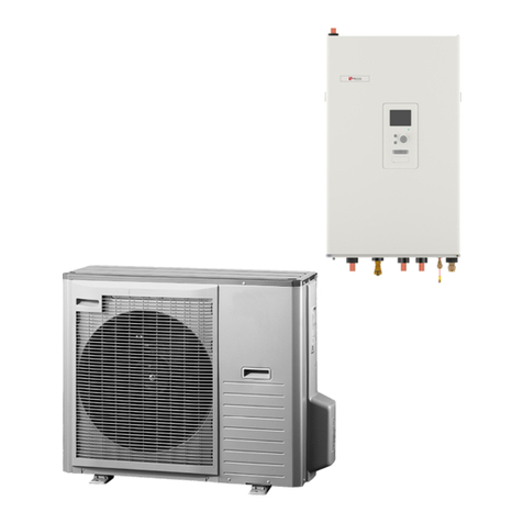
alphainnoTec Hydraulic tower HT7 User manual

UK
83070100bUK
Accessory for
heat pumps
Operating Manual
Hydraulic tower HT7

2Subject to technical amendments without prior notice | 83070100bUK | ait-deutschland GmbH
Contents
1 About this operating manual ...................... 3
1.1 Validity....................................................... 3
1.2 Reference documents............................... 3
1.3 Contact...................................................... 4
2 Safety ............................................................... 4
2.1 Intended use ............................................. 4
2.2 Personnelqualications ............................ 4
2.3 Personal protective equipment ................. 4
2.4 Residual risks............................................ 5
2.5 Avoiding damage to property .................... 5
3 Operation and product care....................... 5
3.1 Energy-conscious and environmentally-
conscious operation.................................. 5
3.2 Product care.............................................. 5
4 Scope of supply............................................. 6
4.1 Accessories............................................... 6
4.2 Components of the unit............................. 6
5 Storage, transport and installation ........... 7
5.1 Storage...................................................... 7
5.2 Unpacking and transport........................... 7
5.3 Transport with handcart ............................ 8
5.4 Carrying the unit........................................ 8
5.5 Installation................................................. 9
6 Hydraulic connection to heating circuit
and domestic hot water ............................. 10
6.1 Heating circuit ..........................................11
6.2 Expansion vessel .....................................11
6.3 Hydraulic connection of the domestic
hot water tank...........................................11
7 Electrical installation................................... 12
7.1 Preparatory work..................................... 12
7.2 Electrical connection............................... 13
8 Installing the control panel........................ 15
9 Flushing,llingandventing ...................... 16
9.1 Heating water quality .............................. 16
9.2 Flushingandllingtheheatingand
domestic hot water charging circuit......... 16
9.3 Flushing,llingandventingthe
domestic hot water tank .......................... 17
10 Insulating hydraulic connections ............. 18
11 Commissioning ............................................ 18
12 Overowvalve ............................................. 18
13 Volumetricowmeter/Heatmeter........ 19
14 Malfunctions ................................................. 19
14.1 Unlocking the safety temperature limiter 19
14.2 Alarm....................................................... 19
14.3 Emergency operation.............................. 20
15 Dismantling and disposal.......................... 20
15.1 Dismantling ............................................. 20
15.2 Disposal and recycling ............................ 20
Technicaldata/Scopeofsupply................... 21
Performance curves .......................................... 22
Dimensional drawings....................................... 23
Installation plans................................................. 24
Terminal diagrams ............................................. 25
Circuit diagrams.................................................. 28

3
Subject to technical amendments without prior notice | 83070100bUK | ait-deutschland GmbH
1 About this operating manual
This operating manual is part of the unit.
►Before working on or with the unit, always read
the operating manual carefully and follow it for all
activities at all times, especially the warnings and
safety instructions.
►Keep the operating manual to hand by the unit,
and give it to the new owner if the unit changes
hands.
►If you have any questions or anything is unclear,
ask the local partner of the manufacturer or the
factory's customer service.
►Observe all reference documents.
1.1 Validity
This operating manual refers solely to the unit identi-
edbythenameplate.
1.2 Reference documents
The following documents contain supplementary infor-
mation for this operating manual:
●Planning & design manual, hydraulic integration
●Heat pump operating manual
●Heating and heat pump controller HPC operating
manual
●Log book
●If necessary: operating manuals for accessories
Symbols and markings
Identicationofwarnings
Symbol Meaning
Safety information. Risk of physical
injury.
DANGER Indicates imminent danger resulting
in severe injuries or death.
WARNING Indicates a potentially dangerous
situation which may result in severe
injuries or death.
CAUTION Indicates a potentially dangerous
situation which may result in mod-
erate or minor injuries.
IMPORTANT Indicates a potentially dangerous
situation which may result in dam-
age to property.
Symbols in the document
Symbol Meaning
Informationforqualiedpersonnel
Informationfortheowner/operator
Required action
Procedural instructions:
Individual step to take
1., 2., 3., etc. Procedural instructions:
Numbered series of steps, which
should be taken in the listed order
Additional information, e.g. advice
for making work easier, information
about standards
Reference to further information
elsewhere in the operating manual
or in another document
●Bullet point
Secure connections against twist-
ing

4Subject to technical amendments without prior notice | 83070100bUK | ait-deutschland GmbH
1.3 Contact
Up-to-date addresses for purchasing accessories, for
customer service or for answers to questions about
the unit and this operating manual can be found on-
line at:
●Germany: www.alpha-innotec.de
●EU: www.alpha-innotec.com
2 Safety
Do not use the unit if it has any technical defects. On-
ly use it as intended, safely and aware of the hazards,
and follow this operating manual.
2.1 Intended use
The unit is designed for household use and is solely
intended for the following purposes:
●Heating
●Domestic hot water preparation
● Cooling(owtemperatureofupto18°C)
● Swimmingpoolheating(accessories)
● Integrationofphotovoltaicsystems(accessories)
►Intended use includes complying with the oper-
ating conditions ( “Technical data / Scope of
supply”, page 21) and the operating manual, as
well as observing the reference documents.
►When using the unit, observe the local regula-
tions, laws, standards, guidelines and directives.
Any other use of the unit is considered unintended
use.
2.2 Personnelqualications
The operating manual included in the Scope of supply
is intended for all users of the product.
Theproductisintendedforusebyendcustomers/op-
erators, and it can be operated (via the control pan-
el)andworkedonbypersonsofanyagewhounder-
stand the tasks and potential consequences, and who
are able to carry out these necessary tasks.
Children and adults who are inexperienced with the
product and who do not understand the tasks and po-
tential consequences must be briefed and, if neces-
sary, supervised by persons who know how to handle
the product and who are responsible for safety.
Children must not play with the product.
Theproductmayonlybeopenedbyqualiedspecial-
ist personnel.
All procedural instructions in this operating manual are
solelydirectedatqualiedspecialistpersonnel.
Only qualied specialist personnel are able to carry
out work on the unit safely and correctly. Interference
byunqualiedpersonnelcancauselife-threateningin-
juries and damage to property.
►Ensure that the personnel are familiar with the lo-
cal regulations, especially those on safe and haz-
ard-aware working.
► Ensurethatthepersonnelarequaliedtohandle
ammable(primary)refrigerant.
►Work on the refrigerating circuit may only be car-
ried out by qualied personnel with appropriate
qualicationsforrefrigerationsysteminstallation.
► Qualiedpersonnelwithelectricaltrainingarethe
only people permitted to work on the electrics and
electronics.
►Other work on the system should only be carried
outbyqualiedspecialists,suchas:
●Heating engineers
●Plumbers
During the warranty and guarantee period, servicing
and repairs may only be carried out by personnel au-
thorised by the manufacturer.
2.3 Personal protective equipment
During transport and work on the unit, there is a risk of
cuts due to the sharp edges of the unit.
►Wear cut-resistant protective gloves.
During transport and work on the unit, there is a risk of
foot injuries.
►Wear safety shoes.
When working on liquid-conveying lines, there is a risk
of injury to the eyes due to leakage of liquids.
►Wear safety goggles.

5
Subject to technical amendments without prior notice | 83070100bUK | ait-deutschland GmbH
2.4 Residual risks
Injuries caused by electric shock
Components in the unit are energised with life-threat-
ening voltage. Before working on the unit:
►Disconnect unit from power supply.
►Protect unit against being switched back on again.
Existing earthing connections within housings or on
mounting plates must not be changed. If this should
nonetheless be necessary in the course of repair or in-
stallation:
►Restore earthing connections to their original
state once repair or installation is complete.
Injuries caused by high temperatures
►Before working on the unit, let it cool down.
2.5 Avoiding damage to property
Improper action
Requirements for minimising scale and corrosion dam-
age in hot water heating systems:
●Proper planning, design and commissioning
●Corrosion-resistant system
●Integration of an adequately dimensioned device
for maintaining pressure
●Use of demineralised heating water or VDI 2035
equivalent water
●Regular servicing and maintenance
If a system is not planned, designed, started up and
operated in accordance with these requirements,
there is a risk that the following damage and malfunc-
tions will occur:
●Malfunctions and failure of components, e.g.
pumps, valves
●Internal and external leaks, e.g. from heat ex-
changers
●Restrictions and blockages in components, e.g.
heat exchanger, pipes, pumps
●Material fatigue
●Gas bubbles and gas cushion formation (cavita-
tion)
●Impaired heat transfer caused by formation of
coatings, deposits etc., and associated noises,
e.g.boilingnoises,ownoises
►Observe the information in this operating manual
for all work on and with the unit.
Impactoflow-qualityllingandtop-upwater
in the heating circuit
Thequalityoftheheatingwateriscrucialforthee-
ciency of the system and the service life of the heat
generator and the heating components.
Ifthesystemislledwithuntreateddrinkingwater,cal-
cium deposits form as limescale on the heat transfer
surfaces of the heating system. This reduces the unit's
eciencyandincreasesenergycosts.Inextremecas-
es, this will damage the heat exchangers.
► Only ll the system with demineralised heating
water or with VDI 2035 equivalent water (for low-
saltoperationofthesystem).
3 Operation and product care
NOTE
The unit is controlled via the control panel of
the heating and heat pump controller HPC.
3.1 Energy-conscious and
environmentally-conscious
operation
The generally accepted requirements for energy-con-
scious and environmentally-conscious operation of a
heating system also apply to use of a heat pump. The
most important measures include:
● Avoidunnecessarilyhighowtemperatures
●Avoid unnecessarily high domestic hot water tem-
peratures(observeandfollowlocalregulations)
●Do not open windows with just a gap or tilt win-
dows open (continuous ventilation), but instead
open windows wide for a short time (shock ven-
tilation).
●Ensure the controller settings are correct.
3.2 Product care
Wipe down the outside of the unit only using a damp
cloth or a cloth with a mild detergent (washing-up liquid,
neutralcleaningproduct).Donotuseanyharsh,abra-
sive, acidic or chlorine-based cleaning products.


6Subject to technical amendments without prior notice | 83070100bUK | ait-deutschland GmbH
4 Scope of supply
Example of Scope of supply packaging:
2
1
1 Compact unit (domestic hot water tank and
buertank,withoutheatpump)
2 Separate package: Control panel of the
heating and heat pump controller HPC, safety
assembly,pumpballvalves,indoor/outdoor
temperaturesensorRS(Split),adjustablefeet,
230V connecting bridge ( “Terminal diagram
1/2”,page25)
1. Check the delivery for outwardly visible signs of
damage.
2. Ensure everything has been delivered.
Any defects or incorrect deliveries must be report-
ed immediately.
4.1 Accessories
The following accessories are available for the unit
through the manufacturer's local partner:
● Air/magneticdirtseparator
● ExtensionboardEP(Split)
● RoomstationRS(Split)
●Photovoltaics communication and control unit PV
(Split)
● Modbus(Split)
● SwimmingpoolheatingIPP(Split)
4.2 Components of the unit
13
20
11
19
12
2
4
3
10
1
8
6
7
5
9
15
16
17
18
14
1 Shut-oballvalvewithdraintap
*)
2 Shut-oballvalvewithllinganddraintap
*)
3 Circulation pump for heating circuit
4 Flow sensor
5 Overowvalve
6 Electric heating element behind shielding plate
7 Switching valve for domestic hot water
8 Vent valve
9 Heatingcircuitsafetyassembly(insulated)
*)
10Shut-oballvalveforhotwaterinlet(return)
*)
11 Shut-oballvalveforhotwateroutlet(supply)
*)
12Sacricialanode
13Domestichotwatertankandbuertank
14 Control panel
15 Switch box
16 Thermostat for electric heating element
17 Safety temperature limiter
18 Expansion vessel
19Drainingforbuertank
20 Adjustable feet
*)
*) to be installed at the installation site

7
Subject to technical amendments without prior notice | 83070100bUK | ait-deutschland GmbH
5 Storage, transport and
installation
5.1 Storage
►Store the unit so that it is protected against:
● Moisture/damp
●Frost
●Dust and dirt
5.2 Unpacking and transport
Safe transportation of the unit
The unit is heavy ( “Technicaldata/Scopeofsup-
ply”, page 21). There is a risk of injuries or damage
to property if the unit is dropped or knocked over.
There is a risk of cutting your hands on sharp edges
of the unit.
►Wear cut-resistant protective gloves.
The hydraulic connections are not designed for me-
chanical loads.
►Do not lift or transport the unit by the hydraulic
connections.
5. 2 .1 Transport with a pallet truck
5.2.2 Unpacking
1. Removetheplasticlms.Ensurethatyoudonot
damage the unit in the process.
2. Dispose of the transport and packaging material
in an environmentally-friendly manner and in ac-
cordance with local regulations.
3. Remove the lm from the plastic element of the
front panel at the installation site.
We recommend that you do not remove the wooden
pallet if still carrying the unit.
5.2.3 Facilitating transport
To make the unit lighter and easier to transport, the
entirehydraulics(includingcontrollerwithswitchbox)
can be unscrewed at the front.
1.
Right-hand side: Left-hand side:
2.

8Subject to technical amendments without prior notice | 83070100bUK | ait-deutschland GmbH
3. Disconnect the domestic hot water temperature sen-
sor (BT6) inside the switch box and withdraw the
sensor cable out of its grommet in the switch box.
Opening and closing the switch box:
„7.2 Electrical connection“, page 13
Terminals for the domestic hot water temperature
sensor:
„Circuitdiagram2/2“,page29
4.
4x
5.
6.
IMPORTANT
When lifting o the hydraulic system, withdraw the
cable of the domestic hot water temperature sensor
through its grommet in the support plate and place it
behind the support plate. Be careful not to damage
the cable.
7. Re-attach the hydraulics and hood after aligning
the unit.
“5.5 Installation”, page 9
5.3 Transport with handcart
IMPORTANT
Do not damage the hydraulic connections on the rear
of the unit, the hood on the hydraulics or the insula-
tionforthedomestichotwatertankandbuertank.
5.4 Carrying the unit
To make it easier to carry, a T-piece with two double
nipples can be installed on the domestic hot water out-
let. We recommend that you only remove the wooden
pallet after carrying the unit.
►Carry the hydraulic tower HT 7 with 3-4 people to
the installation site.

9
Subject to technical amendments without prior notice | 83070100bUK | ait-deutschland GmbH
5.5 Installation
Installation site
IMPORTANT
Install the unit inside buildings only.
The installation area must be frost-free and dry. It must
meet the relevant local regulations.
“Installation plans”, page 24, and “Dimensional
drawings”, page 23
1. Place the unit on a stable, solid and horizontal
surface, preferably with structural sound insula-
tion.
2. Tilt the unit slowly and carefully from one side.
3. Secure the unit raised at an angle so that it cannot
accidentally tilt back to the initial position.
4. Install the adjustable feet (①)onall3feet.
1
5. Tilt the unit back to the initial position slowly and
carefully.
6. Adjust the 3 adjustable feet so that they are bal-
anced.
7. If the hydraulics have been removed for transport
reasons, screw the hydraulics back on to the tank.
7.1.
IMPORTANT
When mounting the hydraulic system, insert the ca-
ble of the domestic hot water temperature sensor
through its grommet into the support plate. Take care
not to damage the cable.
7. 2 .
7.3 .
4x

10 Subject to technical amendments without prior notice | 83070100bUK | ait-deutschland GmbH
6 Hydraulic connection to heating
circuit and domestic hot water
IMPORTANT
Dirt and deposits in the hydraulic (existing) system
can lead to damage to the unit.
►Ensure that a dirt separator is installed in the
hydraulic system.
►Thoroughly rinse the hydraulic system before con-
necting the unit hydraulic system.
IMPORTANT
Improper loading will damage the copper pipes!
►Secure all connections against twisting.
Cross-sections and lengths of the pipes for the
heating circuit must be adequately dimensioned.
In doing so, it is essential to take into account the
connection cables between the heat pump and
the hydraulic tower HT 7.
The free compression of the circulation pump
must produce at least the minimum throughput re-
quired for the unit type ( “Free compression”,
page22).
► Routeallhydraulicconnectioncablesasxedpip-
ingandattachthemviaaxedpointtothewallor
ceiling at a maximum distance of 20 cm from the
centre of the respective unit connection.
►Insert vents at the highest points of the heating
circuit.
► Take o the hood at the front of the hydraulic
tower HT 7 ( “5.2.3 Facilitating transport”,
page7).
8. Feed the cable of the domestic hot water temper-
ature sensor (BT6) through its grommet into the
switch box and connect it.
Opening and closing the switch box:
„7.2 Electrical connection“, page 13
Terminals for the domestic hot water temperature
sensor:
„Circuitdiagram2/2“,page29
9. If no further hydraulic or electrical work is being
carried out for the time being, put the hood on the
hydraulics.
9.1.
6x
9.2.
Right-hand side: Left-hand side:

11
Subject to technical amendments without prior notice | 83070100bUK | ait-deutschland GmbH
6.1 Heating circuit
Safetyassemblyandshut-oballvalves
1. Remove the safety assembly and shut-o ball
valves from the separate package and install them
on the connections provided for this purpose.
2. Lay the safety discharge of the safety valve into
the drain via a funnel waste trap according to the
relevant standards and guidelines.
It is essential that the safety discharge is connect-
ed.
Heating water inlet and outlet
1. Establish the hydraulic connection to the unit.
2. Establish the hydraulic connection to the heating
circuit.
Position of the connections: “Dimensional draw-
ings”, page 23
6.2 Expansion vessel
The expansion vessel for the heating circuit is inte-
grated.
Always check whether the expansion vessel is large
enough for the system. If necessary, an additional ex-
pansion vessel must be installed on site according to
the relevant standards.
NOTE
The initial pressure of the expansion vessel
must be adjusted to the system (approx. 0.5
bar less than the system lling pressure) as
calculated in accordance with the relevant
standards(EN12828).
6.3 Hydraulic connection of the
domestic hot water tank
Connect the domestic hot water tank in accordance
with DIN 1988 and DIN 4753 Part 1 (or the relevant lo-
calstandardsandguidelines).
Position of the connections: “Dimensional draw-
ings”, page 23
Do not exceed the operating pressures indicated on
the nameplate. Install a pressure reducer if necessary.
The sensor for domestic hot water preparation is al-
ready clamped in the switch box.
IMPORTANT
The electrical conductivity of the domestic hot wa-
termustbe>100µS/cmandmustbeoftherequired
quality for drinking water.

12 Subject to technical amendments without prior notice | 83070100bUK | ait-deutschland GmbH
7 Electrical installation
IMPORTANT
Anincorrectrotatingeldwillcauseirreparabledam-
age to the compressor.
► Ensurethatthereisaclockwiserotatingeld for
the compressor load in-feed.
Basic electrical connection information
● Thespecicationsofthelocalenergysupplycom-
pany may apply to electrical connections.
●Equip the power supply for the heat pump with an
all-pole circuit breaker with at least 3 mm contact
spacing(accordingtoIEC60947-2)
●Observe the level of the tripping current (“Tech-
nicaldata/Scopeofsupply”,page21)
●Comply with the electromagnetic compatibility
(EMC)regulations
●Lay power supply cables and communication ca-
blessucientlyfarapart(>100mm)
●Cable on site
Permitted type of communication cable:
3x0.75mm²,(LiYY,EKKXorequivalent),
maximum cable length: 20 m
For the hydraulic tower HT 7 load cable:
One 3 x 2.5mm² cable with protective conductor,
diameter of sheath cable 10 mm
For the electric heating element load cable:
One 5 x 2.5mm² cable with protective conductor,
diameter of sheath cable 9-13 mm
7.1 Preparatory work
Installationofoutdoorsensors(required)
IMPORTANT
Install one of the RS (Split) sensors supplied with
the unit on the north or north-east side of buildings.
RS(Split)mustnotbeexposedtodirectsunlightand
must be installed so that it is protected from rain. The
cable entry into the housing must point towards the
ground.
1. Open the RS (Split) housing and align ≥ 2 m
above the ground at a suitable mounting point.
2. Mark and drill mounting holes. Hammer down the
wall plugs and screw the housing with cable entry
down to the wall.
3. Close the housing.
IMPORTANT
Moisture must no be trapped in the housing. If nec-
essary, completely drain the inside of the housing be-
fore installing the housing cover.
Make sure that the housing is leaktight as a result
of the zero potential installation and that water can-
not penetrate the housing at any time (for example,
duringtheconstructionstage).Sealanyexistingca-
ble ducts.
4. Route the sensor cable to the inside of the build-
ing and to the electrical switch box of the hydraulic
tower HT 7.
5. ConnectthesensorcableasBT1(outdoorsensor).
“7.2 Electrical connection”, from page 13
Installingaroomtemperaturesensor(optional)
NOTE
The control system works without a room
temperature sensor. However, in order to
read the current indoor temperature on the
display of the control panel and to change
the room temperature via the control system,
a room temperature sensor must be installed
and activated in the control system menu.
1. Install RS (Split) in a neutral location where the
set temperature is desired.
An example of a suitable location is a free interior wall
inthehallandapprox.1.5mfromtheoor.
NOTE
The sensor must not be prevented from mea-
suring a correct room temperature – for ex-
ample, by placing it in a niche, between
shelves, behind a curtain, above or near a
heat source, in a draught area of the exter-
nal door or in direct sunlight. Closed radiator
thermostats can also cause problems.
Changes of temperature in the home take time. For
example, switching underoor heating on for a short
period of time will not lead to a noticeable change in
room temperature.
If the RS (Split) is placed in a room with underoor
heating, it should only have a display function and no
control function for the room temperature.

13
Subject to technical amendments without prior notice | 83070100bUK | ait-deutschland GmbH
7. 2 Electrical connection
The electrical connection is established via the electri-
cal switch box.
1. Insert the control and sensor cables, the load and
communication cable from the heat pump, the ca-
ble for the EVU lock and all cables for external
consumers through the grommet on the rear of
the unit (①)intotheinsideoftheunit.
1
1
2
2. Route the cable through the cable duct (②)tothe
electrical switch box.
3. Open the side cover (②) of the electrical switch
box.
2
2
4. Strip the cable before inserting it into the electri-
cal switch box (strip 6mm of each of the individu-
alwires).
5. Route the cable through the openings in the bot-
tom of the electrical switch box to the terminals in
the electrical switch box.
6. Connect the outdoor sensor (BT1) to terminal
AA3-X6:1-2.
2. Route the sensor cable to the electrical switch
box of the hydraulic tower HT 7.
3. ConnectthesensorcableasBT50(roomsensor)
according to the terminal diagram.
“Terminaldiagram2/2”,page26
4. Activate the room temperature sensor later in
menu 1.9.4 of the heating and heat pump control-
ler HPC.
NOTE
If there are multiple heating circuits, we rec-
ommendthatyouusetheRS(Split)accesso-
ries for each individual heating circuit.
Networkcable(optional)
There is the option of connecting the control panel to
a computer or a network in order to control the heating
and heat pump controller HPC from there.
►Route a shielded network cable (category 6,
withRJ-45plug)throughtheunittotheelectrical
switch box.

14 Subject to technical amendments without prior notice | 83070100bUK | ait-deutschland GmbH
BT1 Hydraulic tower HT 7
7. Make further connections as shown in the termi-
nal diagrams.
“Terminal diagrams”, from page 25
The hydraulic tower HT 7 is connected on site accord-
ing to the following schematic diagram:
5
1 Heat pump
2 Load compressor
3 Communication cable
4 Hydraulic tower HT7
5 Load cable of heating element
6 Control voltage of the heating and heat pump
controller HPC
7 Load compressor
8 Sub-distribution/Mainpowersupply
8. Secure all cables inserted into the switch box with
strain relief in the electrical switch box and route
plug-in connections for the control panel out of
the opening (③) in the front cover of the electri-
cal switch box.
3
9. Close the electrical switch box by re-attaching the
side cover.

15
Subject to technical amendments without prior notice | 83070100bUK | ait-deutschland GmbH
8 Installing the control panel
1. Remove the control panel from the separate pack-
age and hang it on its 3 hooks in the switchgear
compartment panel.
2. Press the control panel downwards until the lock
(①)snapsintothelowergroove(②)ontheswitch-
gear compartment panel.
3x
2
!
1
3. Insert the plug into the corresponding socket at
the bottom of the control panel.
2 31
1 RJ45femaleconnector(AA4-X9)fornetwork
cable(optional)
2 Socket(AA4-X8)for10-pinplugofterminal
block AA3-X2
3 6-pinplugsocket(remainsunoccupied)
Dismantling the control panel
1. Insert the small slotted screwdriver from above in-
to the upper lock (③)andpressonthehandlein
the direction of the control panel until the lock of
the control panel is released from its anchoring.
3
2. Liftthecontrolpanel upwardsrst, andthen for-
ward from the hook brackets.
3. Disconnect the plug-in connections from the con-
trol panel.

16 Subject to technical amendments without prior notice | 83070100bUK | ait-deutschland GmbH
9 Flushing,llingandventing
9.1 Heating water quality
NOTE
●For detailed information, see also the
VDI Guidelines 2035 "Vermeidung von
Schäden in Warmwasserheizanlagen"
(preventing damage in hot water heating
systems).
●Required pH value: 8.2-10;
For aluminium materials:
pH value: 8.2-8.5
► Only ll the system with demineralised heating
water or with VDI 2035 equivalent water (for low-
saltoperationofthesystem).
Advantages of low-salt operation:
●Minimal corrosion
●No formation of mineral scale
●Ideal for closed heating circuits
● IdealpHvalueduetoself-alkalisationafterlling
the system
►If the required water quality is not achieved, con-
sult a company that specialises in treatment of
heating water.
►It is advisable to keep a system log for hot water
heating systems containing the relevant planning
&designdata(VDI2035).
Anti-freeze in the heating circuit
For air/water heat pumps installed outdoors, it is not
necessary to add a water-antifreeze mixture into the
heating circuit.
The heat pumps have safety devices which prevent
the water from freezing even when the heating is
switchedo.Theprerequisiteisthattheheatpumpre-
mains switched on and is not disconnected from the
power supply. If there is a risk of frost, the circulation
pumps are activated.
Ifthe heatingcircuitislledwith anti-freeze,andde-
pending on the concentration of the mixture, the fol-
lowing points must be observed:
●The heating capacity of the heat pump is reduced
●The COP value becomes worse
●The output of circulation pumps used on site is re-
duced,andthespeciedfreecompressionforin-
tegrated circulation pumps decreases
●You must ensure the materials in the components
used are compatible with the anti-freeze mixture
9.2 Flushingandllingtheheating
and domestic hot water charging
circuit
The outlet pipe of the safety valve must be con-
nected.
►Ensure that the set pressure of the safety valve is
not exceeded.
1. Vent the system at the highest point in each case.
2. Vent the heat pump on the hydraulic connection
set.
3. Open the vent valve (①) on the 3-way switching
valve.
1
4. Pull the U-clip (②) on the rear of the valve motor (③)
upwards on the 3-way switching valve.
2
3
4

17
Subject to technical amendments without prior notice | 83070100bUK | ait-deutschland GmbH
5. Pull the valve motor (③) forward carefully from the
3-way switching valve (④).
43
6. Turn the spindle of the 3-way switching valve so
that the rounded side of the spindle points to-
wards marking A of the connections of the 3-way
switching valve.
A
B
7. Flush the domestic hot water charging circuit for
approx. 1 minute.
8. Turn the spindle so that the rounded side of the
spindle points towards marking B of the connec-
tions of the 3-way switching valve.
9. Flush the heating circuit thoroughly, until no more
air is discharged.
10. Position the valve motor (③) on the 3-way switch-
ing valve (④).
43
11. Insert the U-clip (②) on the rear of the valve mo-
tor (③).
2
12. Ensure that the U-clip has latched into position
correctly:
The valve motor must sit securely on the 3-way
switching valve
Both prongs of the U-clip must sit on the lug
You must be able to see no more than approx.
2 mm of the tips of the U-clip
13. Close the vent valve (①) on the 3-way switching
valve.
9.3 Flushing,llingandventingthe
domestic hot water tank
IMPORTANT
Before ushing and lling the domestic hot water
tank, the outlet pipe of the safety valve must be con-
nected. The set pressure of the safety valve must not
be exceeded.
1. Open the domestic cold water inlet valve on the
domestic hot water tank.
2. Open the domestic hot water valves on the taps.
3. Flush the domestic hot water tank until air is no
longer discharged from the valves on the taps.
4. Close the domestic hot water valves on the taps.

18 Subject to technical amendments without prior notice | 83070100bUK | ait-deutschland GmbH
10 Insulating hydraulic
connections
Insulate hydraulic lines in accordance with local regu-
lations.
1. Openshut-odevices.
2. Perform a pressure test and check for leaks.
3. Insulate external piping on site.
4. Insulateallconnections,ttingsandpipes.
11 Commissioning
►Place the hood on the hydraulics of the unit be-
fore connecting the power supply of the unit and
commissioning (“5.2.3 Facilitating transport”,
page7).
Check that:
The water supply to the domestic hot water tank
is open
The domestic hot water tank and heating circuit
arelled
Allshut-odevicesontheunitareopen
All vent valves are completely closed
The safety temperature limiter has not tripped
(“14.1 Unlocking the safety temperature lim-
iter”,page19)
Hydraulic installation and electrical connection
work have been carried out properly.
►Follow the instructions for commissioning in the
heating and heat pump controller HPC operating
manual.
Heating and heat pump controller HPC operating
manual, “Commissioning and setting” section
12 Overowvalve
The overow valve adjustment procedure should be
performed as follows during system startup:
1. Opentheoverowvalve(➀)completely.
Turn the adjusting knob (②)ontheoverowvalve
totherighttoincreasethetemperaturedierence
(thetemperaturedrop),andturnittothelefttore-
duce it.
1
2. Close the ow on all heating circuits after the
overowvalve.
3. Go to menu 5.6 “Forced control” and manually set
the speed of the feed pump to 100%.
4. Continue to menu 3.1.11.
5. Close the overow valve by a quarter of a turn
at one-minute intervals, while checking the ow
rate indicator in menu 3.1.11. When the “Minimum
owduringdefrosting”valueisreached,closethe
overowvalvefully.
6. In menu 5.6 “Forced control”, open the heating
circuits again and set the circulation pump to au-
tomatic operation.

19
Subject to technical amendments without prior notice | 83070100bUK | ait-deutschland GmbH
13 Volumetricowmeter/
Heat meter
Theintegratedvolumetricowmeter/heatmeter(①)
is used to measure the heat quantity generated by the
heating system and made available for domestic hot
water preparation and building heating.
1
Thevolumetricowmeter/heatmetermeasuresow
and temperature dierence in the charging circuit.
The measuring ranges are set in the heating and heat
pump controller HPC. Measured values can be read
out on the control panel display.
Heating and heat pump controller HPC operating
manual, menu 5.3.21
14 Malfunctions
14.1 Unlocking the safety temperature
limiter
A safety temperature limiter is installed in the electri-
cal switch box. If the heat pump fails or there is air in
the system:
►Check whether the Reset button (①) on the safety
temperature limiter has tripped.
1
NOTE
The safety temperature limiter interrupts the
power supply from the electric heating mod-
ule when the temperature rises to approx.
98°Cordropsbelow-8°C.
►If the Reset button has tripped, press it again with
a little force using a small screwdriver.
►If the safety temperature limiter trips again, con-
tact the local partner of the manufacturer or the
factory's customer service.
14.2 Alarm
Heating and heat pump controller HPC operating
manual, “Comfort malfunction” section

20 Subject to technical amendments without prior notice | 83070100bUK | ait-deutschland GmbH
14.3 Emergency operation
Heating and heat pump controller HPC operating
manual, “Comfort malfunction” section
Thermostat for emergency operation
In emergency operation, the ow temperature is set
via the electric heating element thermostat (①) ac-
cording to the needs of the heating circuits in opera-
tion.
Adjustmentrange:40°C–80°C
Factory setting: Stop on left-hand side = frost protec-
tion
1
►Set the temperature of the thermostat to the de-
signed heating system.
IMPORTANT
Setting the temperature too high can damage the in-
sulation and the heating system.
NOTE
The maximum available heating capacity in
emergency operation is 2 kW.
15 Dismantling and disposal
15.1 Dismantling
►Separate components by their materials.
15.2 Disposal and recycling
►Recycle unit components and packaging materi-
als in accordance with local regulations, or ensure
they are disposed of properly.
Table of contents
Other alphainnoTec Heat Pump Accessories manuals

alphainnoTec
alphainnoTec Dual HTD User manual

alphainnoTec
alphainnoTec Dual HTD User manual

alphainnoTec
alphainnoTec LW 160H/V User manual

alphainnoTec
alphainnoTec HSV 9M1/3 User manual

alphainnoTec
alphainnoTec HM 6Split User manual

alphainnoTec
alphainnoTec Luxtronik User manual

alphainnoTec
alphainnoTec Hydraulic Module 2 User manual