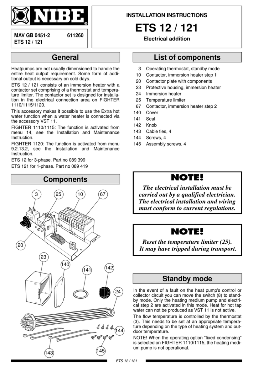
alphainnoTec LW 160H/V User manual

www.alpha-innotec.com
UK
Heating- and heat pump control
Part 2
83055400kUK – 2.1
OPERATING MANUAL
LUXTRONIK
Scope of delivery, Montage,
Electrical connections,
Installation of sensors, Dismantling
Software update
Switching on / Commissioning
Program area “Cooling“
Program area “Service“
Program area “Parallel mode“
Appendix

2Subject to technical amendments without prior notice | 83055400kUK – 2.1 | ait-deutschland GmbH
Please read rst
This operating manual is part 2 of the 2-part operating manual for
the heating and heat pump controller. Ensure that you have part 1
of this operating manual. If part 1 is missing, request it from your
supplier
This operating manual provides important information on the
handling of the unit. It is an integral part of the product and must
be stored so that it is accessible in the immediate vicinity of the
unit. It must remain available throughout the entire service life of
the unit. It must be handed over to subsequent owners or opera-
tors of the unit.
Read the operating manual before working on or operating the
unit. This applies in particular to the chapter on safety. Always fol-
low all instructions completely and without restrictions.
It is possible that this operating manual may contain instructions
that seem incomprehensible or unclear. In case of questions or
uncertainty, contact the factory customer service department or
the manufacturer’s local service partner.
This operating manual is intended only for persons assigned to
work on or operate the unit. Treat all constituent parts conden-
tially. The information contained herein is protected by copyright.
No part of this information may be reproduced, transmitted, cop-
ied, stored in electronic data systems or translated into another
language, either wholly or in part, without the express written
permission of the manufacturer
Symbols
Information for users.
Information or instructions for qualied technicians and
authorised service personnel.
DANGER
Indicates a direct impending danger resulting in severe
injuries or death.
DANGER
Indicates danger to life due to electric current!
WARNING
Indicates a possibly dangerous situation that could re‑
sult in severe injuries or death.
CAUTION
Indicates a possibly dangerous situation that could re‑
sult in medium or light injuries.
IMPORTANT
Indicates a possibly dangerous situation, which could re-
sult in property damage.
NOTE
Emphasized information.
€
ENERGY SAVINGTIP
Indicates suggestions that help to save energy, raw mate-
rials and costs.
Users and qualied technicians can set data.
Access: User.
Authorized installer can set data; password required.
Access: Installer.
Authorised service personnel can set data. Access via
USB stick only.
Access: After sales service.
Factory pre-setting, no data change possible
►Procedural instructions: single step action prompt.
1., 2., 3., … Numbered step within a multi-step instruction for ac-
tion. Adhere to the given sequence.
●List.
9Prerequisite for an action.
Reference to further information elsewhere in the oper-
ating manual or in another document.

3Subject to technical amendments without prior notice | 83055400kUK – 2.1 | ait-deutschland GmbH
Contents
PLEASE READ FIRST.................................................................................................2
SYMBOLS.......................................................................................................................2
SCOPE OF DELIVERY, MONTAGE, ELECTRICAL CONNECTIONS,
INSTALLATION OF SENSORS, DISMANTLING
SCOPE OF DELIVERY...............................................................................................5
Installed control scope of supply..............................................................5
Wall control scope of supply.......................................................................5
MONTAGE......................................................................................................................5
Assembly of the installed control.............................................................5
Assembly of the wall control.......................................................................5
Air/Water outdoor units standard......................................................5
Air/Water outdoor units professional (LWP).................................5
ELECTRICAL CONNECTIONS..............................................................................6
Installation of the Wall-control ..................................................................6
Air/Water outdoor units standard......................................................6
Air/Water outdoor units professional (LWP).................................6
Control unit variants ........................................................................................8
Variants of the motherboard.......................................................................8
Assembly and Installation of sensors.....................................................9
External sensor.................................................................................................9
Hot water sensor.............................................................................................9
External return ow sensor.................................................................... 10
DISMANTLING ......................................................................................................... 10
SOFTWAREUPDATE / DOWNGRADE........................................................ 10
SWITCHING ON / COMMISSIONING........................................................... 10
STARTUP GUIDE ..................................................................................................... 12
Fix startup parameters................................................................................. 13
Reset start-up parameters......................................................................... 13
EMERGENCY MODE.............................................................................................. 14
PROGRAM AREA “COOLING”
SELECT PROGRAM AEREA
.................................................................................. 15
SETTING THE MODE OF OPERATION “COOLING“
...................................... 15
SET TEMPERATURES
............................................................................................. 16
SET PARAMETERS
................................................................................................. 16
COOLING BASED ON SET TEMPERATURE OR
DEPENDING ON OUTDOOR TEMPERATURE
................................................17
ENABLE ACTIVE COOLING
..................................................................................17
PROGRAM AREA “SERVICE“
SELECT PROGRAM AREA
.................................................................................... 18
QUERY INFORMATION
......................................................................................... 18
Query Temperatures.................................................................................. 18
Query inputs................................................................................................... 19
Query outputs............................................................................................... 19
Query elapsed times..................................................................................20
Query operating hours............................................................................. 20
Query error memory..................................................................................20
Query switch os......................................................................................... 20
Query the system status.......................................................................... 21
Query energy monitor.............................................................................. 21
Query heat quantity................................................................................ 21
Query energy input.................................................................................22
Query the history and exporting the history ...........................22
Query building services management system (BMS).............22
Query Smart.................................................................................................... 23
Query InfoLog................................................................................................23
Query Inverter ...............................................................................................23
Query EventLog............................................................................................23
MAKING SETTINGS
............................................................................................... 24
Determine data access.............................................................................. 24
Calling up preset program ..................................................................... 24
Determining temperatures.................................................................... 24
Hot gas utilisation / desuperheater................................................... 27
Determining priorities .............................................................................. 27
Determining system setting.................................................................. 27
Ventilating the system .............................................................................. 31
Fix startup parameters ............................................................................. 32
Back up error memory externally....................................................... 32
Eciency pump............................................................................................ 32
Enter serial number.................................................................................... 33
RBE – room control unit........................................................................... 33
Additional heating generator............................................................... 33
Inverter ..............................................................................................................34
FlexCong........................................................................................................ 35
Silent Mode..................................................................................................... 35
Pump ow lead time.................................................................................. 36
Smart................................................................................................................... 36
Smart Grid........................................................................................................36
Operating states........................................................................................ 37
Set decrease / increase.......................................................................... 37
Terminal diagrams Smart Grid ..........................................................38
SELECTING LANGUAGE OF THE SCREEN DISPLAY
.....................................38
DETERMINING DATE AND TIME
....................................................................... 38
SCREED HEATING PROGRAM
............................................................................ 39
Setting temperatures and time intervals....................................... 39
Starting screed heating program.......................................................40
Manually terminating screed heating program.........................40
HEATPUMP CONFIGURATION
........................................................................... 41
STARTUP GUIDE
.................................................................................................... 41
RESET STARTUP PARAMETERS
........................................................................ 41
DATA LOGGER
........................................................................................................ 41
CONTROL PANEL
................................................................................................... 41
Adjusting the contrast of the
control unit display ................................................................................ 41
Web server....................................................................................................... 41

4Subject to technical amendments without prior notice | 83055400kUK – 2.1 | ait-deutschland GmbH
Remote maintenance................................................................................ 41
Switch on the remote maintenance function .......................... 42
Check connection..................................................................................... 42
Error causes with connection problems...................................... 42
Heatpump24.com..................................................................................... 42
PROGRAM AREA “PARALLEL MODE“
BASIC INFORMATION
..........................................................................................44
Switching on and o for LWP heat pumps....................................44
Switching on and o for Hybrox heat pumps.............................44
Broken connection.........................................................................................44
Connection......................................................................................................... 45
Additional heat generator.........................................................................46
Master – heating mode............................................................................46
Slave –preparing domestic hot water..............................................46
Mixing curcuits.................................................................................................46
Energy monitor................................................................................................46
SELECT PROGRAM AREA
....................................................................................46
IPADRESS
............................................................................................................... 47
Set the network addresses..................................................................... 47
EXTERNAL RETURN FLOW SENSOR
................................................................ 47
SETTING ON THE MASTER
.................................................................................48
Network................................................................................................................48
Search for Slaves...........................................................................................48
Status of the master ...................................................................................48
Set parameters.................................................................................................48
Service Menu..................................................................................................... 49
APPENDIX
ERROR DIAGNOSIS / ERROR MESSAGES.................................................. 50
Acknowledging a fault.................................................................................54
Flashing codes on controller board......................................................54
TECHNICAL DATA .................................................................................................. 55
Installation.......................................................................................................... 55
Outputs ................................................................................................................ 55
Inputs..................................................................................................................... 55
Connections....................................................................................................... 55
Interfaces............................................................................................................. 55
Protection class................................................................................................ 55
Temperature sensor characteristic curve.......................................... 55
Overview: Defrost cycle, Air defrost, Flow Max............................ 56
Sensor measuring range............................................................................. 56
SYSTEM SETTING DURING COMMISSIONING...................................... 57
ABBREVIATIONS SELECTION....................................................................... 61

5Subject to technical amendments without prior notice | 83055400kUK – 2.1 | ait-deutschland GmbH
Montage
ASSEMBLY OF THE INSTALLED CONTROL
In the case of devices for internal mounting, the motherboard of
the heating and heat pump is integrated in the electrical switch
cabinet of the device.
Operating manual of your heat pump, assembly of the con-
trol unit
ASSEMBLY OF THE WALL CONTROL
Air/Water outdoor units standard
Operating Manual wall-mounted controller
Air/Water outdoor units professional (LWP)
For all work to be carried out:
NOTE
Observe the locally-applicable accident prevention regula-
tions, statutory provisions, ordinances and directives.
WARNING
Only qualied technicians may mount the heating and
heat pump control.
1. Position the drill template at the point where the heating
and heat pump control is to be located.
IMPORTANT
Check the potential mounting location for concealed wir-
ing. Position the drill template in such way that no con-
cealed wiring can be drilled into or damaged during the
subsequent assembly work.
NOTE
You need to ensure ≥ 2 cm free space to the right and left
of the drill template, so that there is enough space for the
side fastening screws of the housing cover.
2. Fix drill template onto the wall with adhesive tape, drill holes
(Ø 6 mm, depth ≥ 55 mm).
3. Take drill template o the wall, insert dowels in the holes,
screw in screws (spacing from the substrate to the screw
head approximately 10mm).
Scope of delivery
NOTE
Function-critical temperature sensors (return, inlet, hot
gas) are installed in the heat pump and are not part of the
scope of supply of the heating and heat pump control.
The heating and heat pump control is supplied in two variants.
The variant supplied is dependent on the device type of the heat
pump to the controlled.
INSTALLED CONTROL SCOPE OF SUPPLY
In the case of devices for internal mounting, the motherboard of
the heating and heat pump control is integrated in the relevant
device as an “installed control”. The “installed control” scope of
supply is included in the scope of supply of the device for inter-
nal mounting.
●Heating and heat pump control,
consisting of motherboard (with terminals) and control unit
(with status display, screen and “rotary pushbutton”)
●External sensor for the surface mounting
●Operating manual (in two parts)
●Brief description of the heat pump control.
NOTE
Please fasten brief description in the vicinity of the device.
WALL CONTROL SCOPE OF SUPPLY
In the case of devices for external mounting, the motherboard of
the heating and heat pump control is not integrated in the rele-
vant device but in the wall control.
●Heating and heat pump control for surface mounting,
consisting of motherboard (with terminals), housing and
control unit (with status display, screen and “rotary push-
button”)
●Wall mounting materials (drill template, screws, dowels
for solid masonry)
●External sensor for the surface mounting
●Operating manual (in two parts)
●Brief description of the heat pump control
NOTE
Please fasten brief description in the vicinity of the device.
1. Check the supplied product for signs of external damage dur-
ing delivery.
2. Check that nothing is missing from the scope of supply.
Immediately submit a complaint in the event of delivery de-
fects.

6Subject to technical amendments without prior notice | 83055400kUK – 2.1 | ait-deutschland GmbH
Follow the information in the operating manual of your heat
pump for establishing the electrical connections.
Operating manual of your device, “Electrical Connections“, “Ter-
minal Diagram“ and “Circuit Diagrams“ for your device type
INSTALLATION OF THE WALL-CONTROL
Air/Water outdoor units standard
Operating Manual wall-mounted controller
Air/Water outdoor units professional (LWP)
1. If not yet carried out: Remove housing cover of the heating
and heat pump contro.
section “Montage”, “Assembly of the wall control”, instruc-
tions 4. – 5.
1 Control unit
2 Motherboard of the heating and heat pump control
3 LIN-BUS communication cable between motherboard and
control unit (wired in the factory)
4 Extension board 2.1
5 Terminal block (X10 Modbus) for BUS cable to the outdoor
unit
6 Fastening screw of the folding bracket
7 Cable entry with folding bracket
8 Cable ducts with covers (covers now shown here in the
gure)
9 TRL return sensor terminal (on NTC8)
10 EVU bridges (must be removed when connecting a oating
contact)
11 Terminal block for 1~/N/PE/230 V voltage supply
12 Connection for circulation pump PWM control signal
2. Loosen fastening screw of the folding bracket for the cable
entry and pull the folding bracket downwards until it is possi-
ble to fold away upwards. Fold folding bracket upwards and
away to the side .
3. Remove covers from the cable ducts.
4. Connect the BUS communication cable, which leads to the
heat pump, to terminal block X10 of the controller board.
Then route the BUS communication cable downwards and
through the cable ducts and through the cable entry to the
outside.
NOTE
The wall mounting material included in the scope of sup-
ply requires solid masonry.
IMPORTANT
Ensure that the screws are rmly in the substrate.
4. Loosen right and left fastening screw of the housing cover
for the heating and heat pump controller.
5. Remove housing cover and set aside in a safe place.
6. Hang the heating and heat pump control into the screws on
the wall. Tighten the screws.
1 Rear view 2 Front view
7. If the electrical installation is not to be carried out immedi-
ately afterwards: Put the housing cover back on and tighten
the side fastening screws.
Electrical connections
DANGER
Danger of fatal injury due to electric current!
Electrical connections may be installed only by qualied
electricians.
Before opening the unit, disconnect the system from the
power supply and secure it from being switched back on!
WARNING
During installation and while carrying out electrical
work, comply with the relevant EN‑, VDE and/or local
safety regulations.
Comply with technical connection requirements of the
responsible power supply company (if required by the
latter)!

7Subject to technical amendments without prior notice | 83055400kUK – 2.1 | ait-deutschland GmbH
NOTE
The inputs and outputs on the motherboard are assigned
as shown on the device’s terminal connection diagram.
In addition, the assignment is shown on the inside of the
housing of the wall-mounted controller.
10. Place covers on the cable ducts. Swivel folding bracket of the
cable entry back into the initial position and allow to latch in-
to place below the fastening screw. Tighten fastening screw.
11. Put the housing cover back on and tighten the side fasten-
ing screws.
IMPORTANT
Route all lines that you connect to the heating and heat
pump control outside the heating and heat pump in a ca-
ble duct (necessary for strain relief; to be realised at the
customer).
IMPORTANT
The BUS communication cable must be laid at a spacing >
10 cm from other cables. Therefore, lay with the appropri-
ate spacing in a separate cable duct.
1 1~/N/PE/230V power supply (to the terminal block); cable
cross-section max. 2.5 mm²
2 other 230 V inputs (electricity outage , …)
3 Sensor cables including the TRL return sensor on the return
to the heat pump
4 BUS communication cable to the outdoor unit
5 other 230 V outputs (circulation pumps, mixers, , …)
6 PWM control signal for circulation pump
7 230 V power supply to the outdoor unit
K Cable ducts
5. Connect the 230 V voltage supply line to the voltage supply
terminal block.
NOTE
The terminal block has spring-type terminals to maximum
2.5 mm.
Insulate the cable jacket so that the jacket end is located
between the sealing lip and cable duct.
6. Connect the 230V power supply for the outdoor unit to the
terminal block and route it downwards through the cable
ducts and through the cable entry to the outdoor unit out-
side.
7. Connect the PWM control signal for the circulation pump to
the terminal block X10.
8. A separately packed return sensor (TRL) with appropriate in-
stallation materials is enclosed with the air/water heat pump
for outdoor installation. Use cable ties and heat transfer com-
pound to x the return sensor to the return (heat-conducting
pipe) to the heat pump as shown in the gure and connect
(to NTC8) as shown in the circuit diagram.
Basic wirng:
1 Connect BUS communication cable
2 Laying cables in the cable ducts
3 Connect TRL return sensor (on NTC8)
4 Connect 1~/N/PE/230 V power supply for wall-mounted
controller and outdoor unit
5 Connect PWM control signal for circulation pump
9. If necessary, install additional external cables.
Instruction manual for your appliance, “Connection layout”
and “Circuit diagrams” for your appliance type

8Subject to technical amendments without prior notice | 83055400kUK – 2.1 | ait-deutschland GmbH
I/O MAX motherboard
X11 X12
X13
X10
X14
X1
X2
X3
X4
X5
X6
X7
X8
X9
1 Fuse for relay outputs 6,3 AT
2 Fuse for transformer 1,6 AT
3 Slot for extra board MLRH
4 Slot for expansion board
X1 Terminal block: Control voltage
X2 Terminal block: Interne 230 V Ein- und Ausgänge
X3 Terminal block: 230 V outputs
X4 Terminal block: 230V distribution (continuous current)
X5 Terminal block: 230 V inputs
X6 Terminal block: Connection for expansion valve or
circulation pump PWM
X7 Terminal block: Connection for circulation pump PWM
X8 Terminal block: External sensor inputs
X9 Terminal block: External sensor inputs
X10 Terminal block: Internal sensor inputs
X11 Terminal block: Analog inputs
X12 Terminal block: Analog outputs
X13 Terminal block: LIN-Bus interface (for control unit)
X14 Terminal block: Modbus interface
CONTROL UNIT VARIANTS
Depending on the heat pump type, one of these models of the
control unit is included in the scope of delivery:
Variant 1*) Variant 2*)
*) Variant device-dependent
Assignment of the plugs on the underside of the control unit:
Operating manual of your heat pump.
VARIANTS OF THE MOTHERBOARD
Depending on the heat pump type, the heating and heat pump
controller is equipped with one of the following motherboards:
HZ I/O motherboard
X1
X3-1
X3-2
X4
X9
X8 X10 X11
X6
X7
X2
X5-1
X5-2
1 Fuse for relay outputs 6,3 AT
2 Fuse for transformer 1,6 AT
3 Slot for extra board MLRH
4 Slot for expansion board
X1 Terminal block: Control voltage
X2 Terminal block (is not equipped / unused in the standard
version)
X3-1 Terminal block: 230 V outputs
X3-2 Terminal block: 230 V inputs
X4 Terminal block: 230V distribution (continuous current)
X5-1 Terminal block: External sensor inputs
X5-2 Terminal block: External sensor inputs
X6 Terminal block: Connection for circulation pump PWM
X7 Terminal block (is not equipped / unused in the standard
version)
X8 Terminal block (is not equipped / unused in the standard
version)
X9 Terminal block: Analog outputs and inputs
X10 Terminal block: Modbus interface
X11 Terminal block: LIN-Bus interface (for control unit

9Subject to technical amendments without prior notice | 83055400kUK – 2.1 | ait-deutschland GmbH
Dimensional drawings
All dimensions in mm.
1 Fastening holes (Ø 4,3)
2 Cable gland M16 x 1,5
3 Cable gland SW 20
Hot water sensor
The domestic hot water sensor is an optional accessory and only
functionally-relevant for a separate domestic hot water tank. You
may only use domestic hot water sensors which have been ap-
proved by the manufacturer of the heat pump.
IMPORTANT
The domestic hot water tank must be lled before con-
necting the domestic hot water sensor to the heating and
heat pump control.
If not already prepared at the factory, mount the domestic hot
water sensor (Ø = 6 mm) on the halfway level of the domestic hot
water tank – and always above the internal heat exchanger of the
domestic hot water tank.
1 Domestic hot water connection
2 Cold water connection
3 Heat exchanger
4 Domestic hot water sensor (Ø = 6 mm)
5 Hot-water tank
ASSEMBLY AND INSTALLATION OF SENSORS
External sensor
The external sensor (protection class IP 67) is a function-critical
accessory and included in the scope of supply.
NOTE
If the external sensor is not installed or defective, the heat-
ing and heat pump control automatically sets the external
temperature to -5 °C. The status display of the control unit
lights up red, the screen of the control unit reports an er-
ror.
IMPORTANT
Mount the external sensor on the north or northeast side
of buildings. The sensor must not be exposed to direct
sunlight. The cable gland must point to the base.
1. Open the housing of the external sensor and align ≥ 2 m
over the base of the fastening point.
1 Quick-release screws
2 NTC sensor element 2.2 kΩ at 25 °C
3 Cable clamps
4 Housing sealing in housing cover
2. Mark the xing holes on the xing point and drill them into
the xing point. Insert dowels and screw the housing of the
external sensor to the wall.
NOTE
Dowels and screws for fastening the external sensor are
not included in the scope of supply.
3. Loosen cable gland and lead a 2-wire cabel (Ø 5- 9,5mm, cross
section ≤ 1.5 mm² per wire, cable length ≤50 m) through the
cable gland into the housing.
4. Fit the cable wires with wire end sleeves, place them on the ca-
ble clamps of the external sensor and tighten them with a torque
of 0.5 Nm.
5. Tighten cable glands with a torque of 2.5 Nm and close the
housing of the external sensor. Ensure that the housing seal
and the sealing surfaces are clean and that the housing seal is in
the correct position.
IMPORTANT
No moisture may be trapped in the housing. If necessary,
completely dry the inside of the housing before mounting
the housing cover.
Ensure that the tightness of the housing is guaranteed by
mounting it tension-free and that no water can penetrate
the housing of the external sensor at any time (for instance
during the construction phase).

10 Subject to technical amendments without prior notice | 83055400kUK – 2.1 | ait-deutschland GmbH
External return ow sensor
The return ow sensor (optional accessory) is functionally-rele-
vant for hydraulic integration of an isolating tank (multifunction
tank). This has to be installed as follows:
ZUP TRLext HUP
1 Separation or multi-functional storage tank
2 Circulation pump in the separation storage
tank (heat pump circuit)
3 Circulation pump from the separation storage
tank (heating circuit)
4 External return sensor (Ø = 6 mm)
ZUP Charging loop, heat pump
HUP Discharging loop, heating circuit
Connect the return ow sensor coming from the isolating tank to
the circuit board of the heating and heat pump control.
Dismantling
DANGER
Danger of fatal injury due to electric current!
Electrical connections may be installed only by qualied
electricians.
Before opening the unit, disconnect the system from the
power supply and secure it from being switched back
on!
Softwareupdate / ‑downgrade
Software updates/downgrades can be carried out via the USB in-
terface on the control unit of the heating and heat pump control-
ler.
1. Expose the USB interface on the control unit.
Part 1 of the controller manual, program area “Service“, sec-
tion “Basic Information on the operation“
2. Insert a USB stick with the software into the USB interface
and follow the on-screen instructions.
IMPORTANT
Only install updates/downgrades that are cited as “valid
updates” (“Gültiges Updates”) in the screen list.
Switching on / Commissioning
When switching on the controller voltage or after a restart of the
heating and heat pump controller (reset), a self-test is carried out
to check whether the basic components of the heat pump system
are available.
The components displayed vary depending on the heat
pump type.
The self-test (POST = Power on startup) can take up to
5minutes (Time-out).
Once all the basic components of the system are detected within
5 minutes, the system is ready for operation.
NOTE
If the self-test fails, an emergency mode is activated, if the
necessary components have been detected.
page 14, “Emergency mode“
If the system is ready for operation but not yet congured (initial
switching on), then the language selection is displayed rst.
Select the display language: part 1 of the controller manual,
section “Basis information on the operation“.
NOTE
The language must be conrmed.
Then click on the navigation arrow in the language display.
A screen may then appear prompting you to enter a hydraulic-
code. In this case, enter and conrm the hydrauliccode. If a hy-
draulic code is given, do not change this hydrauliccode, but on-
ly conrm it.
NOTE
The hydrauliccode is axed to the hydraulic unit/ to the
wall-mounted controller.
NOTE
The hydrauliccode can be read later in the “System status”
menu. If necessary, it can be changed there.
page 21, “Query the system status“

11Subject to technical amendments without prior notice | 83055400kUK – 2.1 | ait-deutschland GmbH
The following display then appears:
The question always appears when the controller volt-
age is switched on, provided it has been interrupted for
>20 hours.
If the date and time are correct, select and click . Otherwise,
select and click , set the correct date, time and time zone and
save. Then select and click on the navigation arrow in the display.
After that a security question appears:
The security question always appears when the control-
ler voltage is switched on or after a restart of the heating
and heat pump controller (reset).
This screen is no longer displayed if the heat pump or
ZWE1 has more than 10 operating hours.
No ZWE (additional heating generator) is released by the control-
ler until the display is conrmed with .
NOTE
No heat generator runs during a cold start of air/water heat
pumps.
IMPORTANT
The unit can be damaged if the display is conrmed with
, although the system is not properly lled.
For brine/water heat pumps it is necessary to select which heat
source uid is to be used.
Brine
Must be selected if the heat pump is operated with a
brine-water mixture (= standard). Whether probes or
surface collectors are used is irrelevant.
If there is an intermediate heat exchanger on the heat source
side:
Water Brine
Must be selected if water is used as the heat source me-
dium on the primary side of the intermediate heat ex-
changer and a brine-water mixture is used on its second-
ary side.
Water Water
Must be selected if water is used as the heat source me-
dium on both the primary and secondary sides of the in-
termediate heat exchanger. For the water/water setting
the heat source inlet temperature must be at least 7°C or
higher.
IMPORTANT
Performance-controlled brine/water heat pumps with re-
frigerant R407C shall only be operated on the secondary
side of the intermediate heat exchanger and not with wa-
ter as the heat source medium. Therefore, the menu en-
try “Water Water” is not visible in the display with per-
formance-controlled brine/water heat pumps with refrig-
erant R407C.
The minimum temperature of the heat source (min. heat source
temp) will be set automatically depending on the selected medi-
um.
page 57, “System setting during commissioning“, “min.
heat source temp”
NOTE
If no heat source is selected and the enquiry is only an-
swered by navigating to and selecting , “Brine” is auto-
matically set as the heat source.
A subsequent change of the heat source medium as well
as “T-HS min” is only possible with customer service access.
If this screen
is then displayed, disconnect the heating and heat pump con-
troller from the power supply, check the 3-pole cable for the BUS
connection and rectify any faults found.
After that, the navigation screen appears.
NOTE
With some devices, the compressor is now heated initially.
The heating phase until the compressor starts can take
several hours when starting up for the rst time.
With dual air/water heat pumps the ow is monitored
while the pump is running. If the ow is not ok, the heat
pump does not start up and no error is displayed. To this
end, check the ASD input, if it is not set to ON the ow is
too low.
page 19, “Query inputs“

12 Subject to technical amendments without prior notice | 83055400kUK – 2.1 | ait-deutschland GmbH
So long as the heat pumps have not yet been congured, the
“GO” symbol ashes at the top right of the navigation screen.
Navigating to and clicking on “GO” calls up the startup guide. This
assistant will guide you through the most important settings of
the regulator during initial commissioning.
After the initial commissioning has been completed, the “GO”
symbol will no longer be displayed.
page 12, “Startup guide“ and page 13, “Reset start-up
parameters“
If you do not wish to use the startup guide, rst make the settings
required for your system in the “System settings” menu (page
27, “Determining system setting“).
Then set the desired temperatures ( page 24, “Determining
temperatures“).
Then make all other settings that are necessary for the conditions
of your installation.
Startup guide
If the startup guide is not called up via the ashing “GO” symbol
in the navigation screen, this can be done in the “Service” pro-
gram area.
You will be guided step-by-step through several selection options
used to set up your heat pump.
For example:
For the number of the control setting, please refer to the hydraulic diagrams we have
published.
Further queries will follow.
For more information on the commissioning assistant, please re-
fer to the corresponding sections in this operating manual.
NOTE
As soon as the startup guide has been executed once, the
menu item “Reset start-up parameters” appears on the dis-
play instead of the “Startup guide” menu item.

13Subject to technical amendments without prior notice | 83055400kUK – 2.1 | ait-deutschland GmbH
FIX STARTUP PARAMETERS
With installer or customer service access, it is possible to save the
settings made during commissioning (= startup guide). This al-
lows you to quickly and easily reset the system to the status it had
at startup.
The data is stored on the circuit board of the control unit.
Follow the instructions on the screen and save the set-
tings.
You can also save the settings to an external USB stick.
RESET START-UP PARAMETERS
If your heat pump was commissioned by an authorised customer
service partner and the startup parameters have been stored, you
can use this menu item to restore these parameters.
This may be helpful if settings have been changed and let to a
system malfunction. Please Notice that all settings such as heat-
ing curves, system settings, set values will be reset to the values
applicable at commissioning.
The programmed switching times are not aected by this.
You will be guided through the following menu items:

14 Subject to technical amendments without prior notice | 83055400kUK – 2.1 | ait-deutschland GmbH
Emergency mode
The emergency mode provides heating operation and domestic
hot water preparation as well as the frost protection function and
the screed heating program even if, after switching on the con-
troller voltage and during the self-test (POST Screen)
●one or more basic system components were not detected,
●at least the system components required for the emer-
gency mode were detected.
The emergency mode is activated automatically.
NOTE
For units where a hydraulic code must be entered during
commissioning, the emergency mode can only start if this
hydraulic code has been entered.
A connection error is rst displayed on the screen of the heating
and heat pump controller.
Im Bildschirm des Heizungs- und Wärmepumpenreglers wird zu-
nächst ein Kommunikationsfehler ausgegeben.
Example of a connection error displayed on the screen.
Beispiel eines im Bildschirm angezeigten Kommunika-
tionsfehlers
The navigation screen is displayed by turning the “rotary push-
button”.
If the emergency mode is active, corresponding warning symbols
are shown in the standard screen.
During the emergency mode, the compressor request is locked.
To ensure heating operation and domestic hot water preparation,
set the “2nd heat gen.” option as the “Heating” operating mode
and the “Domestic hot water” operating mode.
NOTE
The “2nd heat gen.” setting increases the energy consump-
tion.
During the emergency mode, the search for missing system com-
ponents continues in the background.
If the missing components are detected during the emergency
mode, the system is automatically restarted.
NOTE
The operating modes “Heating“ and “Domestic hot water“
must be manually reset from the option “2nd heat gen.” to
the option “Auto(matic)”.
If the compressor of the heat pump fails during operation, the op-
erating modes “Heating” and “Domestic hot water” can also be
set to the option “2nd heat gen.” if required.
This can ensure that heating and domestic hot water are prepared
until the cause of the compressor failure has been rectied.

15Subject to technical amendments without prior notice | 83055400kUK – 2.1 | ait-deutschland GmbH
Program area “Cooling”
The “Cooling” function with automatic changeover between
heating mode and cooling mode (depending on requirements)
can be used with a mixing circuit.
In order to use the cooling function with further mixing circuits,
the installation of the expansion board (extra-cost accessory) is
required.
The program area “Cooling” must be set by authorised service
personnel during commissioning.
Necessary setting:
Mixing circ 1 = Cool
page 27, “Determining system setting“, “Mixing circ 1”
IMPORTANT
If a cooling circle mixer is connected, it is imperative to ac-
tivate the function “Cooling”, as otherwise malfunctions
will occur in the mixer connected.
IMPORTANT
The use of cooling requires that you integrate a dew point
sensor in the system. This must then either be connected
in series with the cooling sensor or used instead of the
bridge, if cooling is provided via the ow cooler.
NOTE
The minimum ow temperature of cooling is factory set to
18°C. This value can be changed in the menu “Determin-
ing temperatures” in the menu item “min. ow cooling”
IMPORTANT
For brine/water heat pumps with integrated hydraulic
components, do not set the minimum ow temperature of
cooling to <18°C.
page 24, “Determining temperatures“
If the cooling function is set, the symbol for the program area
“Cooling” will appear in the navigation screen
SELECT PROGRAM AEREA
Menu eld “mode of operation“
leads to the menu “Cooling mode of operation“
Menu eld “Temperatur + –“
leads to the menu “Cooling Temperature“
Menu eld “Parameter“
leads to the menu “Cooling Parameter“
SETTING THE MODE OF OPERATION “COOLING“
The current mode of operation is highlighted with :
Auto
Switches the cooling function on depending on the
outside temperature release or in accordance with a xed
set temperature (= setpoint temperature).
O
Cooling is generally deactivated.
NOTE
Cooling is always the lowest priority.
Example: If there is a demand for domestic hot water, the
cooling will be interrupted or not released.

16 Subject to technical amendments without prior notice | 83055400kUK – 2.1 | ait-deutschland GmbH
NOTE
Activate the automatic mode only during the summer
months or shut o the cooling during the heating period
by means of a room thermostat.
Otherwise, it is possible that, depending on the location of
the outdoor sensor, the system will switch to cooling if the
outdoor temperature exceeds the set temperature.
NOTE
Automatic operation also means that during the summer
months the system will automatically change over to heat-
ing mode or to the operating mode selected in the “Heat-
ing” program area as soon as the outside temperature
drops below the preset value.
In order to ensure that the system does not start to heat
during the summer months, the operating mode for the
heating can be set to “O”.
Part 1 of the controller manual, program area “Heating“, sec-
tion “Setting the operating mode for the heating“
SET TEMPERATURES
release OT
Required outdoor temperature release
The cooling is enabled for the duration of the time set un-
der “Parameters” when above the preset value.
Set parameter
target temp. MC1
Required set temperature for cooling in mixing circle 1
The target value determines the control variable for the ac-
tivated cooling mixer, insofar as the cooling is to be carried
out based on a xed temperature. If cooling enable is set
based on the outside temperature (set. AT.), the menu eld
“OT di. MC1” appears here. Then enter a corresponding
temperature spread in Kelvin.
hysteresis CC Hysteresis cooling regulator
Without an expansion board installed, displayed only for
reversible air/water heat pumps and controls the auto-
matic changeover from passive to active cooling
A
B
K
K
DC
A There will be a request for active cooling in this tem-
perature range
B There will be no request for active cooling in this tem-
perature range
C Neutral zone
D Set temperature of mixing circuit
K Hysteresis in Kelvin
target return cooling
Menu eld “Target return cooling” is shown only with
some reversible air/water-heatpumps.
SET PARAMETERS
OT – excess (maximum outside temperature)
Cooling starts in the “Automatic” operating mode if the
outdoor temperature is exceeded for longer than the time
set under “OT – excess” or once by more than 5K.
OT – undercut (minimum outside temperature)
Cooling is terminated in the “Automatic” operating mode
if the outdoor temperature falls below the set time for
“OT – undercut” for longer than the outdoor temperature
max. room. temp. (maximum room temperature)
The menu eld for regulating the cooling based on room
temperature depending on the outside temperature ap-
pears only if the system has a room control unit (RBE) and
the corresponding settings have been implemented.
Operating manual RBE – Room control unit
NOTE
For brine/water- and water/water-heat pumps the cooling
will only be enabled if the brine inlet temperature is >2 °C.
The set setpoint temperature denes the ow temperature
of the heat pump during cooling.

17Subject to technical amendments without prior notice | 83055400kUK – 2.1 | ait-deutschland GmbH
COOLING BASED ON SET TEMPERATURE OR
DEPENDING ON OUTDOOR TEMPERATURE
The cooling can be released based on the outdoor temperature
or in accordance with a xed temperature (= set temperature).
Cooling based on set temperature
With the “xed Tp” setting, the supply temperature of the cooling
represents the setpoint temperature set for the mixing circuit1
(MC1):
A Temperature
B Time
1 Outdoor temperature
2 xed Tp ( = set temperature mixing circuit)
Cooling depending on outdoor temperature
With setting “set. AT” set temperatures are ignored. Instead, set
temperatures are automatically calculated based on the outdoor
temperature.
The calculation is based on the value entered in Kelvin under “OT
di. MC1” but is restricted to a spread of 1K– 10K (adjustable in
0.5 steps).
A Temperature
B Time
1 Outdoor temperature
2 Set temperature mixing circiut
3 set. AT (= outdoor temperature dierence)
ENABLE ACTIVE COOLING
NOTE
The active cooling function can only be used if the system
is utilised in accordance with the corresponding hydraulic
diagram.
There is otherwise no guarantee that the active cooling
with function properly.
NOTE
For brine/water heat pumps, active cooling is only possible
if the expansion board (extra-cost accessory) is installed.
IMPORTANT
The use of active cooling is generally excluded for brine/
water heat pumps with integrated passive cooling func-
tion.
The active cooling function may only be used if the heating and
heat pump controls are equipped with software >3.31.

18 Subject to technical amendments without prior notice | 83055400kUK – 2.1 | ait-deutschland GmbH
Query Temperatures
The menu is not shown in full here.
ow Flow temperature heating circle
target ow temp. Flow setpoint temperature heating circle
return Return ow temp. of heating circle
Return target Return setpoint heating circle
return external Return temp. in separate tank.
hot gas Hot gas temperature
outdoor temp. External temperature
outdoor temp. Ø Average temperature outside over
24h(function heating limit)
DHW Domestic hot water actual temperature
upper DHW Temperature in the upper part of the
domestic hot water tank
DHW target Domestic hot water target
temperature
heat source inlet Heat source inlet temperature
Heat source out Heat source outlet temperature
mix circ1 ow Mixing circle 1
Forward ow temperature
mix circ1 target Mixing circle 1
Forward ow set temperature
Roomstation Current temperature of the room
control unit (RBE)
In addition – depending on the unit type of the connected heat
pump – the cooling circuit information provided by sensors in the
cooling circuit appears here.
max ow temp. Maximum ow temperature
suction compressor Compressor suction temperature
suction evaporator Evaporator suction temperature
compressor heating Compressor heating temperature
overheating Overheating temperature
target overheating Overheating target temperature
evaporator temp. EVI Evaporator temperature EVI
suction EVi Suction temperature EVI
EVi Superheat Superheating temperature EVI
Target EVI superheat Superheating target temperature EVI
condensing temp. Condensing temperature
Liquid temp before EEV Temperature of the liquid refrigerant
upstream of the electronic expansion
valve (heating)
evaporating temp. Evaporation temperature
condensing temp. Condensation temperature
TFL1 Temperature of the liquid refrigerant
upstream of the electronic expansion
valve (heating)
TFL2 Temperature of the liquid refrigerant
upstream of the electronic expansion
valve (cooling)
subcooling EEV Calculated subcooling at the electronic
expansion valve
Hot gas limit Maximum hot gas temperature
Defrost End Target temperature in the evaporator
to end defrosting
desuperheater Temperature at the desuperheater
Program area “Service“
NOTE
The software automatically detects the connected heat
pump type. Parameters that are not relevant for the con-
ditions of the system and/or the heat pump type are hid-
den. Some of the parameters documented in this program
area may therefore not appear on the screen of your heat-
ing and heat pump controller.
Many menus require scrolling with the “rotary pushbut-
ton”.
NOTE
Some menu entries and parameters are also only visible or
adjustable when installation technician or customer ser-
vice access is active. The dierent data access levels are
marked in this operating manual by symbols.
page 2, “Symbols“
NOTE
Some parameters have adjustable value ranges. These can
be found in the appendix.
page 57, “System setting during commissioning“
SELECT PROGRAM AREA
QUERY INFORMATION

19Subject to technical amendments without prior notice | 83055400kUK – 2.1 | ait-deutschland GmbH
EVI pressure Pressure, EVI pressure sensor
Inverter voltage Mains voltage from the energy supplier
(EVU)
COPS on = Accessory COPS is activated
Query outputs
The menu is not shown in full here.
Defrost demand Defrost request
dv-defrost valve Valve / Circuit reversal
ON = Thaw mode or rather cycle
reversal becomes active
BUP Domestic hot water circulation pump
FP 1 Floor heating circulation pump
HUP Heating circulation pump
MA1 Mixer 1 opens
On = opens / O = no control
MZ1 Mixer 1 Close
On = closes / O = no control
Ventilation Ventilation of the heat pump housing
for certain L/W devices.
For L/W size types (coding “L2G”),
second stage of the ventilator
VBO Ventilator, well or brine circulation
pump
Compressor Compressor(s) in heat pump
Compressor 1 Compressor 1 in heat pump
Compressor 2 Compressor 2 in heat pump
ZIP Circulation pump
ZUP Additional circulating pump
ZWE 1 Additional heating generator 1
ZWE 2 Additional heating generator 2–
Collective fault (function collective
fault: Continuous ON in the event
of a fault, cycles 1x per second with
automatic RESET enabled)
AO … Analogue output … (power supply e.g.
for ow sensor)
compressor heating Compressor heating
HUP Heating circulating pump power in %
ZUP Additional circulating pump power in %
freq. targ.value Target compressor speed
freg. current Current compressor speed
freq. min. Minimum compressor speed
freq. max. Maximum compressor speed
control signal CP Circulation pump output in %
rotation speed fan Current speed of the heat pump’s fan
rotation speed VD Current speed of the heat pump’
compressor
EVi opening Enhanced vapour injection, opening
EEV opening Electronic expansion valve,opening
EEV heating Electronic expansion valve, heating
EEV cooling Electronic expansion valve, cooling
VBO targ. value Setpoint brine circulation pump
VBO current Current value brine circulation pump
HUP targ. value Setpoint heating circulating pump
Switch box Temperature in the electrical switch
box
DSH Hot gas overheating temperature
DSH target Hot gas overheating target
temperature
Query inputs
The menu is not shown in full here.
NOTE
This menu shows whether the digital inputs of the control-
ler are switched on or o.
ASD Defrost, Brine pressure, ow
Depending on the device type, the
input can full various functions:
For L/W-devices
Defrost end pressostat:
On = Defrost is terminated.
For LWP, S/W and W/W devices with ow
switch connected at the factory:
On = Flow okay.
For S/W-devices without ow switch
connected at the factory, a brine
pressostat can be connected:
On = brine pressure sucient.
SW-therm. switch Domestic hot water thermostat
On = Domestic hot water requirement
EVU O-time of the electrical supplier
O = O-time
HD High-pressure pressostat
O = Pressure okay
MOT Motor protection
On = Motor protection okay.
ND Low pressure pressostat
On = Pressure okay.
potent. ext. Connection of an external current
anode (possible for some devices)
Analog In … Analogue input signal (e.g. for ow
sensor)
release cooling ON = cooling enabled (from external)
present
HD High-pressure sensor
ND Low-pressure sensor
ow rate Heating circuit ow rate
smart grid 1 EVU blocking time
2 decreased operating mode
3 normal operating mode
4 increased operating mode
page 37, “Operating states“
EVU 2 Additional energy supplier (EVU) signal
for displaying the Smart Grid states
STB immersion heater Safety temperature limiter (STB)
for monitoring the electric heating
element
ON = STB OK
OFF = STB has triggered

20 Subject to technical amendments without prior notice | 83055400kUK – 2.1 | ait-deutschland GmbH
NOTE
The compressors are only energised alternately follow-
ing the impulses. A variation in the operation hours of the
compressors is, therefore, possible.
Query error memory
728
Error number (here by way of example)
16.10.19
Date of the resulting error (here by way of example)
13:28
Time of the error that occurred
If an entry is clicked, the corresponding information for this entry
is displayed.
Meaning of the error numbers: page 50
NOTE
Maximum the last ve resulting errors are displayed.
Query switch os
16.10.19
Date of the disconnection (here by way of example)
13:53
Time of the disconnection (here by way of example)
El. Sup. bl
Disconnection code (here by way of example)
err. HP heat pump fault
err. inst. system fault
OM ZWE mode of operation additional heating
generator
EVU-block el. sup. blockade
Defr. air. air defrost
TPLmax temperature limits maximum of
application
TPLmin temperature limits minimum of
application
low lim lower limit of application
no requ. no request
TEE External energy source
ow Flow
p0_break Low pressure pause
u0_break Superheating pause
HUP current Current value heating circulating pump
ZUP targ. value Setpoint additional circulating pump
ZUP current Current value additional circulating
pump
Query elapsed times
The menu is not shown in full here.
HP since Heat pump running since
(Time indication respectively in
hh:mm:ss)
ZWE1 since Additional heating generator 1 running
since
ZWE2 since Additional heating generator 2 running
since
net-input delay Net input delay
SCB time O-time switching cycle
VD o since Compressor downtime
hc add-time Heating control more time
hc less-time Heating time less time
TDI since Thermal disinfection running since
blockade DHW O-time domestic hot water
release ZWE Heat. Duration of the release of the
additional heating generator in heating
mode
release ZWE DHW Duration of the release of the
additional heating generator during
domestic hot water preparation
release cooling Duration of the release of the cooling
Defrosting Time until the next defrosting
block 2.VD HG Disabling of 2nd compressor in the
event of hot gas exceedance
Query operating hours
The menu is not shown in full here.
operating hours VD1 Operation hours compressor 1
Impulse VD1 Impulses compressor 1
running time Ø VD1 average duration compressor 1
operating hours VD2 Operation hours compressor 2
Impulse VD2 Impulses compressor 2
running time Ø VD2 average duration compressor 2
operating hours ZWE1 Operation hours additional heating
generator 1
operating hours ZWE2 Operation hours additional heating
generator 2
operation hours HP Operation hours Heat pump
operat. hours heat Operation hours Heating
operation hours DHW Operation hours domestic hot water
operat. hours cool Operation hours Cooling
Other manuals for LW 160H/V
1
This manual suits for next models
17
Table of contents
Other alphainnoTec Heat Pump Accessories manuals

alphainnoTec
alphainnoTec Dual HTD User manual

alphainnoTec
alphainnoTec Dual HTD User manual

alphainnoTec
alphainnoTec HSV 9M1/3 User manual

alphainnoTec
alphainnoTec Luxtronik User manual

alphainnoTec
alphainnoTec Hydraulic Module 2 User manual

alphainnoTec
alphainnoTec Hydraulic tower HT7 User manual

alphainnoTec
alphainnoTec HM 6Split User manual