Alphamount APPSLTK2 User manual

V2.0
TV Wall Mount Instruction Manual
Model: APPSLTK2
Thank you for choosing this Alphamount product! At Alphamount we strive
to provide you with the best quality products and services in the industry.
Should you have any issues, please don't hesitate to contact us at

1
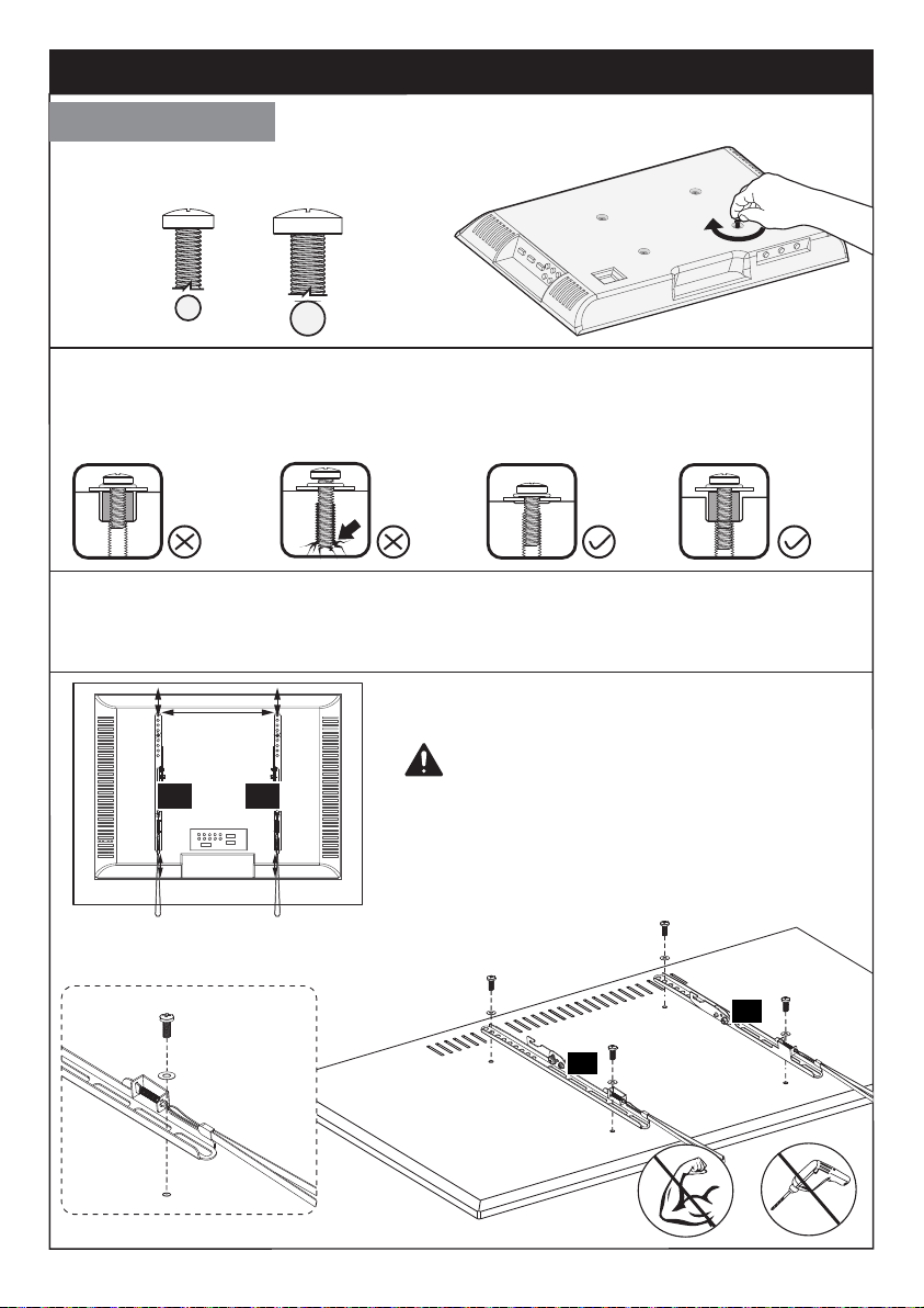
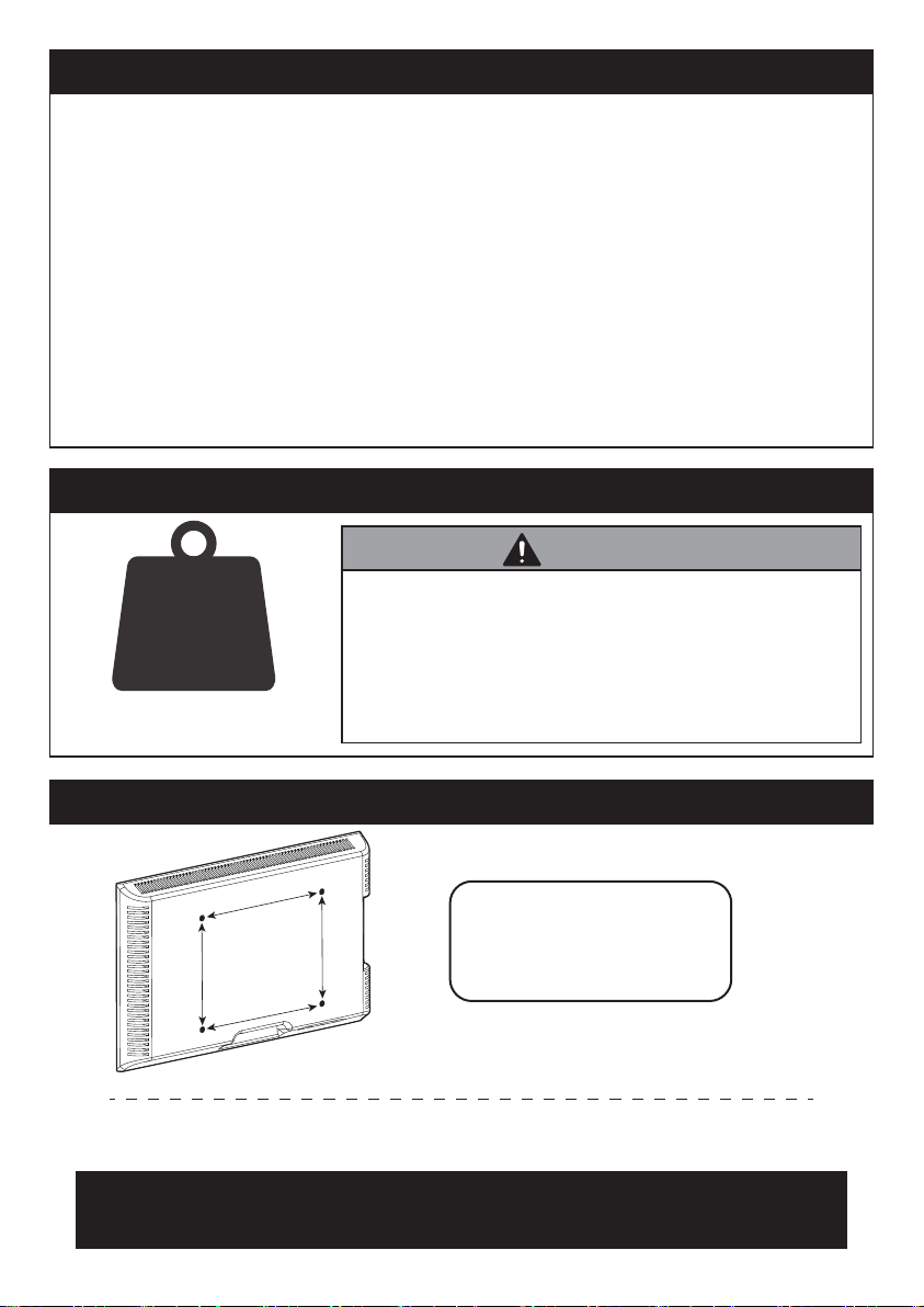
Check the VESA Pattern of TV before the Installation
100 mm ≈ 4 in.
200 mm ≈ 7 7/8 in.
600 mm ≈ 23 5/8 in.
400 mm ≈ 15 3/4 in.
Minimum VESA pattern: 100mm/4 in.(W)x100mm/4 in.(H)
If your TV VESA is greater than 600x400 mm/24x16in. or less than
VESA 100x100mm/4x4 in., this mount is NOT compatible.
If this mount is NOT compatible, please contact customer service at
[email protected] to find a compatible mount.
MAX: 600mm/23.6 in.
MAX: 400mm/16 in.
IMPORTANT SAFETY INFORMATION
Please carefully read all instructions before attempting installation. If you do
not understand the instructions or have any concerns or questions, please
CAUTION: Avoid potential personal injuries and property damage!
• Do not use this product for any purpose that is not explicitly specified in this
manual. Do not exceed weight capacity. We are not liable for damage or injury
caused by improper mounting, incorrect assembly or inappropriate use.
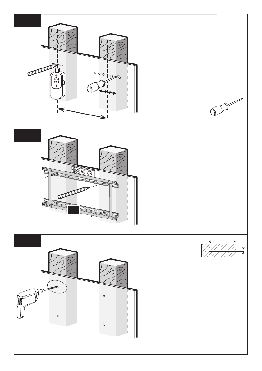
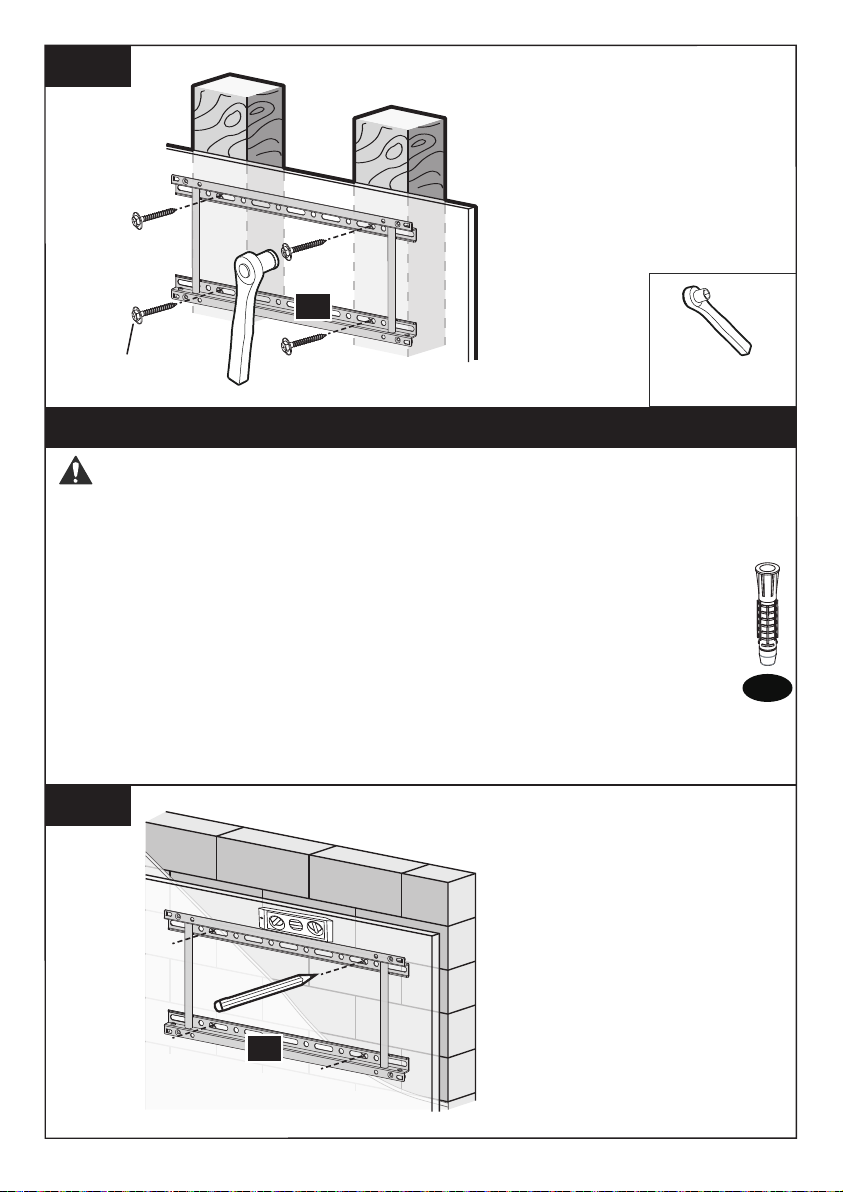
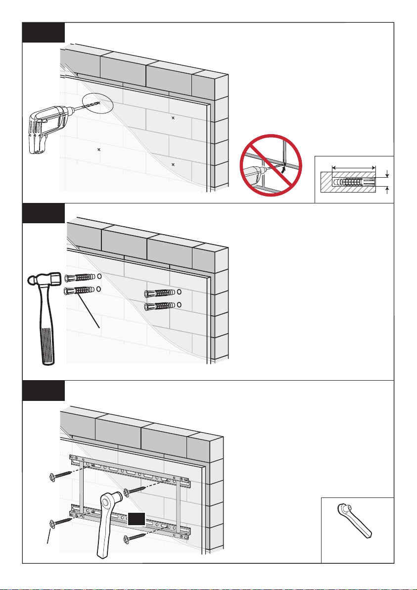
• This product is designed for use in wood stud, solid concrete, and concrete
block walls -
DO NOT install into drywall alone.
• The wall must be capable of supporting five times the weight of the TV and
mount combined.
Weight Restrictions
DO NOT exceed the maximum weight indicated.
This mounting system is intended for use only
with the maximum weights indicated. Use with
products heavier than the maximum weights
indicated may result in failure of the mount and
its accessories, causing damage and or injury.
If your TV weighs more, this
mount is NOT compatible.
132lbs/
60kg
WARNING

2
Tools Needed (Not lncluded)
Supplied Parts and Hardware for Step 1
Left TV Bracket x1
04
Right TV Bracket x1
05
Stud Finder Tape Measure Pencil Drill
5/32 in. (4mm)
Wood Drill
3/8 in. (10mm)
Concrete Drill
1/2in. (13mm)
Socket Wrench
Philips
Screwdriver
Hammer 3/8 in. (10mm)
Wrench
Awl
Washer
M6 Spacer
L5mm
Spacer
L10mm
x4
B
x8
C1
x8
C2
Note: The spacers
are shown in
accordance with
the actual size
Verify Your Wall Construction
Solid Concrete
or Concrete Block
CAUTION
DO NOT
install into
drywall alone Wood Studs
(with Drywall)
If you are not sure the
wall construction, please
contact our customer
service at
Supplied Parts and Hardware
Warning: This product contains small items that could be a choking hazard if swallowed.
Before starting assembly, verify all parts are included and undamaged. Do not use
damaged or defective parts. lf you require replacement parts, please contact our
• Please note: Not all hardware included in this package will be used.

x4 Wall
Anchor
Lag Screw
M7x55 mm
x4
3
Wall Plate x1
01
Note: The lag screw is shown in accordance with the actual size
These anchors are for
concrete or brick walls
ONLY. DO NOT use them in
drywall or wood studs.
CAUTION!
Supplied Parts and Hardware for Step 2 and 3
A1
A2
x4
D1
x4
D2
x4
E1
x4
E2
x4
E3
M6x15mm
Bolt
M6x30mm
Bolt
M8x15mm
Bolt
M8x45mm
Bolt
M8x65mm
Bolt
Note: The bolts are shown in accordance with the actual size
Level
Wall Plate Extension x1
02
Wall Plate Extension x1
03

Only one bolt size fits your TV.
4
Step 1 Secure the TV Brackets to TV
M6 M8
Select TV Bolts
Bolt length: Verify adequate thread engagement with bolts or bolts/spacers
combination. We recommend thread engagement by at least 5 turns.
-Too short will not hold the TV.
-Too long will damage the TV.
Note: If necessary, the spacers can be used in multi-layer. If the installation
fails after trying various methods, please contact customer service at
Too Long
Correct Correct
Too Short
CAUTION: Ensure the TV brackets
[04] and [05] are EQUALLY CENTERED
on your TV AND securely fastened in
place.
05 04
Option A (For Flat Back TV)
05
04
B
(If needed)
D1/ E1

Option D
For cable interference or inset holes, use spacers [C1] and [C2] to create extra
space between the TV and TV brackets
5
D2/ E2/ E3
C1/ C2
B (If
needed)
05
Option B (For Round Back TV)
05
04
B
(If needed)
D2/ E2/ E3
C1/ C2
05
04
Spacers may be necessary for 2 holes ONLY.
Option C (For TV with A “Bump”)
03
B
(If needed)
D2/ E2/ E3
C1/ C2
03
D1/ E1
B
(If needed)
05
Alternate
Spacer
Setups
Alternate
Spacer
Setups
Alternate
Spacer
Setups

6
Step 2 Assemble the Wall Plate
Step 3 Attach Wall Plate to Wall
Step 3A Wood Stud Option
X
For wood stud installation, follow STEP 3A
For concrete installation, follow STEP 3B
WARNING:
Ensure the wall plate is securely fastened to the wall before
continuing to the next step.
● Any material covering the wall must not exceed 5/8 in. (16 mm)
● Nominal wood stud size: common 2 x 4 in. (51 x 102 mm) minimum
1.5 x 3.5 in. (38 x 89 mm)
● Stud center must be verified
Avoid potential personal injury or property damage! DO NOT over-tighten the
lag screws [A1]. Tighten the lag screws [A1] only until they are pulled firmly
against the wall plate [01] or [01, 02 and 03].
DO NOT USE ANCHOR FOR THIS STEP
A2
16 in. (406mm) stud spacing
and
VESA Pattern of TV:
100x100-400x400mm
18-24 in. (457mm-610mm)
stud spacing
or
VESA Pattern of TV:
100x100-600x400mm
Option A:
Option B:
DO NOT overtighten.
Tighten only until snug.
01
Tighten
Tighten
03
02
Loosen
01 01

7
3A-1
3A-2
3A-3
awl
(not included)
Use a stud finder (not included)
to locate wood studs or use an
awl (not included) to verify the
edges. Mark the edge and
center locations.
Drill 4 pilot holes using a 5/32
in. (4mm) diameter drill bit.
Make sure the depth is not less
than 2 11/64 in. (55mm)
Position the wall plate [01] or
[01, 02 and 03] at your desired
height and line up the holes
with your stud center line. Level
the wall plate and mark the
holes.
24in. (610mm)
16in. (406mm)
ø5/32 in. (4mm)
2 11/64 in. (55mm)
01

8
3A-4
Step 3B Solid Concrete or Concrete Block Option
3B-1
Wall
Anchor
WARNING:
Ensure the wall plate is securely fastened to the wall before
continuing to the next step.
● Mount the wall plate [01] or [01, 02 and 03] directly onto the
concrete surface
● Anything covering the wall must not exceed 5/8 in. (16 mm)
● Minimum solid concrete thickness: 203 mm (8 in.)
● Minimum concrete block size: 203 x 203 x 406 mm (8 x 8 x 16 in.)
● Never drill into the mortar between blocks
Avoid potential personal injury or property damage! DO NOT over-tighten the
lag screws [A1]. Tighten the lag screws [A1] only until they are pulled firmly
against the wall plate [01] or [01, 02 and 03].
A2
1/2 in.(13mm)
Socket Wrench
Install the wall plate [01] or
[01, 02 and 03] using lag
screws [A].
Tighten the lag screws [A]
only until they are pulled
firmly against the wall plate.
Position the wall wall plate
[01] or [01, 02 and 03] at
your desired height, level
the wall plate and mark the
pilot hole locations.
01
A1
01

9
3B-2
3B-3
3B-4
1/2 in. (13mm)
Socket Wrench
Use the hammer to knock
anchors [A2] into the wall. Be
sure the anchors [A2] are
seated flush with the concrete
surface.
Install the wall plate [01] or
[01, 02 and 03] using lag
screws [A1]. Tighten the lag
screws [A1] only until they are
pulled firmly against the wall
plate. DO NOT over-tighten
the lag screws [A1].
Drill 4 pilot holes using a
3/8 in. (10mm) diameter drill
bit. Make sure the depth is
not less than 2 23/64 in.
(60mm). Never drill into the
mortar between blocks.
ø3/8 in. (10mm)
2 23/64 in. (60mm)
A2
01
A1

10
Step 4 Adjust Tilt Angles of TV
Step 5 Hang TV onto the Wall Plate [01] or [01, 02 and 03]
05
04
01
03
02
3/8 in. (10mm)
Wrench
Loosen the 4 pcs tilt preassembled bolts [S] in both brackets [04 and 05].
Adjust the hooks [H] to your desired angle. Then tighten the 4 pcs tilt
preassembled bolts [S] with a screwdriver (not included) to fix the tilting angle.
Note:The tilt angles of the hooks on the TV brackets must be the same
Tighten
Loosen
S
H
S
S
Note: Do not over-tighten
or over-loosen the bolts [S]
05
04
HEAVY! You may need
assistance with this step.

Unlocking
R
Disconnect all cables, pull down and hold both cords [R] while gently pulling the
bottom of the TV away from the wall.
CAUTION: Avoid potential personal injury or property damage! To prevent
breaking the locking latches: always pull and hold the cords [R] down while pulling
the TV away from the wall.
Then lift the TV up and off of wall plate assembly [01] or [01, 02 and 03]. Place
the TV on cardbard or other protective surface to avoid damage.
NOTE: To rehang the TV, follow the procedures in Step 5 and 6.
Locking
Pull down and hold both cords [R]. Press the bottom of the TV into the wall
plate assembly [01] or [01, 02 and 03] until the latches lock the TV in place.
Press
R
Step 6 Secure TV
Step 7 Remove the TV
11
HEAVY! You may need
assistance with this step.
01
04
05 02
03
Table of contents
Other Alphamount TV Mount manuals