manuals.online logo
Brands
  1. Home
  2. •
  3. Brands
  4. •
  5. Alphatech
  6. •
  7. Intercom System
  8. •
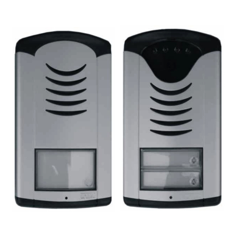
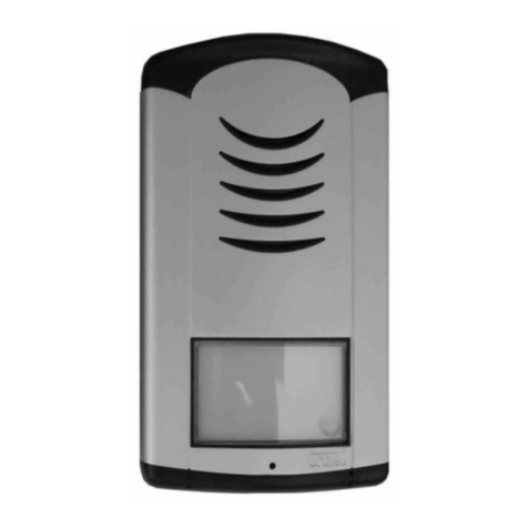
  9. Alphatech IP BOLD65 series User manual

Alphatech IP BOLD65 series User manual

ALPHATECH TECHNOLOGIES s.r.o.
Jeremenkova 88, Praha 4, Czech Republic
www.alphatechtechnologies.cz
141 00 Praha 4
IP BOLD65 quick setup guide
Firts steps before you start programming the unit
Warning: before you start working with the unit, please read instructions below to avoid losing the
warranty.
Item No. 230501 IP BOLD65 T1C Item No. 230502 IP BOLD65 T2C
ALPHATECH TECHNOLOGIES s.r.o.
Jeremenkova 88, Praha 4, Czech Republic
www.alphatechtechnologies.cz
141 00 Praha 4
Thank you for purchasing the IP BOLD65 video doorphone.
Initially select your correct place of installation to achieve the best results. IP BOLD65 is designed to
be surface mounted. Before mounting the IP BOLD65, please check that the place of installation
meets the following requirements as shown at the Fig 1 below. Persons with an average height will be
displayed well on the screen of IP videophone or your computer screen if you install the camera at
160cm height above the ground. The camera should not be installed at places where the sun is shining
to the camera directly, where there is a very strong, intensive light source or where there are reflexive
materials used. This will cause a bad image quality.
Fig 1 Correct height of installation, camera should be installed at 160cm height above the ground level
Installation is done with four twist screws and four wall plugs.
Mounting plate –see Fig. 2 below.
Recommended:
- 4x wall plug with a diameter of 8mm
- 4x screw (a twist) with a half-round head. Diameter 5mm, length 35mm
!!! On the screws please use the supplied rubber rings for protection against water leakages !!!
We recommend the following surface mounting procedure:
- Open the front cover of the unit, disconnect the call buttons cable (point 22, Fig. 5 below)
- Use the supplied rubber bushing for all cables (ETH UTP cable, power supply adapter cable, relay
wires)
- Lead in the cables and wires through the rubber busing (see Fig. 8 below)
Fix the unit safely to the surface of the wall (use screws with wall plugs). Fix all 4 screw holes and do not
forget to use the rubber rings for screws to avoid water leakages.
- Be careful to provide enough space inside the wall behing the IP BOLD65 unit for the rubber bushing to
avoid damaging the rubber busing, jamming and damaging the cables, see Fig. 10 below
- Connect all the wires, see Fig. 13 and next Figures
- Close the top front cover of the unit, see Fig. 3 with the closed top front cover.
ALPHATECH TECHNOLOGIES s.r.o.
Jeremenkova 88, Praha 4, Czech Republic
www.alphatechtechnologies.cz
141 00 Praha 4
Fig 2. IP BOLD65 mounting plate
ALPHATECH TECHNOLOGIES s.r.o.
Jeremenkova 88, Praha 4, Czech Republic
www.alphatechtechnologies.cz
141 00 Praha 4
Before you connect the IP BOLD65 to your network, let´s make a few initial steps. On Fig 3 below
you can see the contents of the packing box.
Fig. 3 Contents of IP BOLD65 T2C packing. 4x wall plug, 4x twist screw with rubber rings, 1x rubber
bushing for leading in the cables and wires, 1x allen key. The IP BOLD65 unit is quite heavy, so
please place underneath the unit a protection (e.g. a paper cartoon box) to avoid damaging your table

ALPHATECH TECHNOLOGIES s.r.o.
Jeremenkova 88, Praha 4, Czech Republic
www.alphatechtechnologies.cz
141 00 Praha 4
Open the IP BOLD65 using the supplied allen key, see Fig 4 below. Open the top front cover slowly
and carefully. As you can see on the Fig 4 below, the call buttons are connected to the main board via
the yellow/white/green cable, so make sure you do not damage it. It is better to disconnect this call
buttons cable before you continue working the unit.
Fig 4 –Open your IP BOLD65 using a supplied allen key, make sure you do not damage the cable
connector, connection to the call buttons or the cable itself. It is better to disconnect the call buttons
cable.
If you unplug the call buttons cable from the connector (point 22 at Fig 5 below), it will be easier to
detach the front cover and work with the doorphone. Connector´s orientation is based on the colours of
the cable.
Fig 5 Unplug the call buttons cable (point 22) to detach the front cover easily.
ALPHATECH TECHNOLOGIES s.r.o.
Jeremenkova 88, Praha 4, Czech Republic
www.alphatechtechnologies.cz
141 00 Praha 4
Slowly and carefully, unscrew the illuminated name/house number module using a cross head
screwdriver, see black arrows at Fig 6 below on the left side. Be careful, the illuminated module is
connected to the main board via a black cable, so unscrew and detach it slowly and carefully to avoid
damaging the connection cable, the cable connector or the illumimated info module. You can also
disconnect this cable to avoid damaging it, it will be easier to continue your work with the unit. Avoid
breaking the white/red cable leading to the microphone at the bottom part of the unit, see Fig 6 below.
Fig 6. Using a cross head screwdriver, detach the top illuminated info module carefully (name/house
number module). On the top front of the illuminated info module you can place your own label with
your name, a house number or your required information, see Fig 19 for more details on changing the
name plate.
To avoid water leakages into the unit, please make sure to use the rubber busing (Fig. 4 below) for
ETH UTP cable, power supply adapter cable and relays wiring.
Fig. 7 Apply rubber bushing to avoid water leakages into the unit
ALPHATECH TECHNOLOGIES s.r.o.
Jeremenkova 88, Praha 4, Czech Republic
www.alphatechtechnologies.cz
141 00 Praha 4
Ethernet UTP cable, the power supply adapter cable and relay wires need to be lead through the IP67
rubber bushing, see Fig 8 below.
Fig 8. Use the rubber busing with IP67 impregnation rating to avoid any leakages inside the unit
ALPHATECH TECHNOLOGIES s.r.o.
Jeremenkova 88, Praha 4, Czech Republic
www.alphatechtechnologies.cz
141 00 Praha 4
Use the IP67 rubber busing for leading the cables and wires inside the IP BOLD65 unit.
Fig 9. Use the IP67 rubber busing to avoid any leakages inside the unit
Use the IP67 rubber busing for leading the cables and wires inside the IP BOLD65 unit. Make sure it
is attached tightly to the housing, so the rubber busing does not fall back inside the unit.
Fig 10. Use the rubber busing with IP67 impregnation rating to avoid any leakages inside the unit.
Make sure there is enough space behing the unit inside the wall to avoid jamming the cables,
damaging the rubber busing and damaging the cables.
ALPHATECH TECHNOLOGIES s.r.o.
Jeremenkova 88, Praha 4, Czech Republic
www.alphatechtechnologies.cz
141 00 Praha 4
Use the rubber busing to avoid any leakages inside the unit
Fig 11. Use the rubber busing to avoid any leakages inside the unit
ALPHATECH TECHNOLOGIES s.r.o.
Jeremenkova 88, Praha 4, Czech Republic
www.alphatechtechnologies.cz
141 00 Praha 4
Before closing the top front cover of the IP BOLD 65 unit, always use screws with rubber rings to
avoid any leakages inside the unit. There are 4 screws holes for 4 screws with rubber rings, two at the
top and two at the bottom of the unit. This ensures the unit is well attached/mounted to the surface of
the wall.
Fig 12. Use screws with rubber rings to avoid any leakages inside the unit
ALPHATECH TECHNOLOGIES s.r.o.
Jeremenkova 88, Praha 4, Czech Republic
www.alphatechtechnologies.cz
141 00 Praha 4
Power supply: via PoE (according to IEEE802.3af) –see the Fig. 13 and Fig. 14 below or via an
optional, external power supply adapter 12VDC/1A (recommended) or 12VAC/1A
Fig. 13 –ETH UTP cable connection, PoE enabled
Ethernet UTP cable connection (also see the figure 13 above):
Fig. 14 Ethernet UTP cable connection
ALPHATECH TECHNOLOGIES s.r.o.
Jeremenkova 88, Praha 4, Czech Republic
www.alphatechtechnologies.cz
141 00 Praha 4
IP BOLD65 has two physical relay contacts on the main board. See Fig 15 below
Fig 15 Relay contacts of the IP BOLD65 doorphone
It is recommended to use for IP BOLD65 PoE powering (according to the directive IEEE802.3af) or
AC voltage min.11VAC input - max.15VAC input or DC voltage min.12VDC - max.18VDC. which
is connected to screw "12V". See Fig 16 below. The IP BOLD65 has a power consumption of
max.300mA. This power supply can be used at the same time also for powering electrical lock(s). In
such a case you need to consider power consumption of the el.lock(s). In most cases using an AC or
DC version of the power supply adapter 12V/1A÷2A is acceptable.
Fig 16 Terminal connectors for relays and 12 power input and output
ALPHATECH TECHNOLOGIES s.r.o.
Jeremenkova 88, Praha 4, Czech Republic
www.alphatechtechnologies.cz
141 00 Praha 4
At Fig 17 and Fig 18 below you can see several examples of relays use
Fig 17 Examples of relays use
ALPHATECH TECHNOLOGIES s.r.o.
Jeremenkova 88, Praha 4, Czech Republic
www.alphatechtechnologies.cz
141 00 Praha 4
Fig 18 Examples of relays use
ALPHATECH TECHNOLOGIES s.r.o.
Jeremenkova 88, Praha 4, Czech Republic
www.alphatechtechnologies.cz
141 00 Praha 4
Changing the name plate (paper label), Fig. 19 below. Name plate size is 78x54mm. Print your text on
the white paper label and fix the paper label (name plate) with a fixing, transparent adhesive tape to
the upper and lower part of the illuminated info module to avoid moving the paper label. The paper
label is fixed between the top front cover and the illuminated info module, so make sure you use an
adhesive transparent tape to fix it well. Then the name plate will not move when closing the top front
cover.
Fig.19 Name plate changing, fix it with a transparent adhesive tape.
How to access the web interface of the unit and start the setup?
Setup on your PC a default IP address in the segment of 192.168.1.xxx. In your web browser, enter
URL address 192.168.1.250, make sure your computer is inside the same network segment. Then enter
the default user name admin and the password 1234 to access the web interface setup menu of the IP
BOLD65 unit for the first time. When entering the default user name, make sure you do not have
CAPS LOCK activated on your computer. Use lower case letters only to enter the default user name
admin correctly.
Fig 20. Enter the default IP address, default user name and default password. Be careful about CAPS
LOCK on your PC, use lower case letters only
Default IP address: 192.168.1.250
Default user name: admin
Default password: 1234
ALPHATECH TECHNOLOGIES s.r.o.
Jeremenkova 88, Praha 4, Czech Republic
www.alphatechtechnologies.cz
141 00 Praha 4
Click on icon Setup, see Fig 21 below to enter the web interface setup menu of IP BOLD65
Fig 21. Click on Setup to enter the web interface setup menu
The initial status page of the web interface, see Fig 22 below
Fig 22. The initial status page of the IP BOLD65 video doorphone
ALPHATECH TECHNOLOGIES s.r.o.
Jeremenkova 88, Praha 4, Czech Republic
www.alphatechtechnologies.cz
141 00 Praha 4
Then follow the standard setup user´s guide of IP BOLD65 doorphone:
http://www.alphatechtechnologies.cz/en/products/voip-door-phones/ip-door-entry-phone-station-ip-bold/
The latest available firmware: http://www.alphatechtechnologies.cz/en/firmware-update-ip-bold/
The latest news including user´s guide of IP BOLD65:
http://www.alphatechtechnologies.cz/en/products/voip-door-phones/ip-door-entry-phone-station-ip-bold/

This manual suits for next models

2

Other Alphatech Intercom System manuals
Alphatech IPDPS-01C User manual

Alphatech

Alphatech IPDPS-01C User manual

Alphatech Fermax Cityline v2 User manual

Alphatech

Alphatech Fermax Cityline v2 User manual

Alphatech NUDV-01 User manual

Alphatech

Alphatech NUDV-01 User manual

Alphatech Fermax PBX EXP Manual

Alphatech

Alphatech Fermax PBX EXP Manual

Alphatech A-VarioBell Troubleshooting guide

Alphatech

Alphatech A-VarioBell Troubleshooting guide

Alphatech IP Bell User manual

Alphatech

Alphatech IP Bell User manual

Alphatech A-Bell-C Troubleshooting guide

Alphatech

Alphatech A-Bell-C Troubleshooting guide

Alphatech SlimDoorPhone - 01 User manual

Alphatech

Alphatech SlimDoorPhone - 01 User manual

Alphatech IP Bold series Installation instructions

Alphatech

Alphatech IP Bold series Installation instructions

Alphatech IP-VarioBell User manual

Alphatech

Alphatech IP-VarioBell User manual

Alphatech Brave Smyle-C User manual

Alphatech

Alphatech Brave Smyle-C User manual

Alphatech GSM-Variobell User manual

Alphatech

Alphatech GSM-Variobell User manual
Alphatech Slim IPDP - 01 User manual

Alphatech

Alphatech Slim IPDP - 01 User manual

Alphatech IP BOLD 65 User manual

Alphatech

Alphatech IP BOLD 65 User manual

Alphatech NUDV-00 Installation instructions

Alphatech

Alphatech NUDV-00 Installation instructions

Alphatech IP BOLD HW Guide

Alphatech

Alphatech IP BOLD HW Guide

Alphatech Slim IPDP - 01 User manual

Alphatech

Alphatech Slim IPDP - 01 User manual

Alphatech Brave series Troubleshooting guide

Alphatech

Alphatech Brave series Troubleshooting guide

Alphatech FTZ123-D12 User manual

Alphatech

Alphatech FTZ123-D12 User manual

Alphatech NFTZ - 01 User manual

Alphatech

Alphatech NFTZ - 01 User manual

Alphatech IP-VarioBell IPVB-01 User manual
Alphatech

Alphatech IP-VarioBell IPVB-01 User manual

Popular Intercom System manuals by other brands

Castel AXESS Series manual

Castel

Castel AXESS Series manual

Elvox Vimar PIXEL UP 40405 user manual

Elvox

Elvox Vimar PIXEL UP 40405 user manual

Telikou MS-800 instruction manual

Telikou

Telikou MS-800 instruction manual

Aiphone GF-1DK Features

Aiphone

Aiphone GF-1DK Features

Vitalinq 94A-07 Operation and installation manual

Vitalinq

Vitalinq 94A-07 Operation and installation manual

Alcad TCB-010 quick start guide

Alcad

Alcad TCB-010 quick start guide

FARFISA INTERCOMS 1PEXFD Installation

FARFISA INTERCOMS

FARFISA INTERCOMS 1PEXFD Installation

GIGAMEDIA GGM IPAI1 owner's manual

GIGAMEDIA

GIGAMEDIA GGM IPAI1 owner's manual

Elvox Vimar TAB Installer manual

Elvox

Elvox Vimar TAB Installer manual

ABB Welcome user manual

ABB

ABB Welcome user manual

Telex 4030 user manual

Telex

Telex 4030 user manual

Sigtronics SPA-600 Installation and operating instructions

Sigtronics

Sigtronics SPA-600 Installation and operating instructions

Commax CMV-70MX user manual

Commax

Commax CMV-70MX user manual

urmet domus 1717 Installation handbook

urmet domus

urmet domus 1717 Installation handbook

golmar GB2A quick guide

golmar

golmar GB2A quick guide

Commax DRC-700S user manual

Commax

Commax DRC-700S user manual

Akuvox R23C user manual

Akuvox

Akuvox R23C user manual

LEXIN LX-B2 user guide

LEXIN

LEXIN LX-B2 user guide

manuals.online logo
manuals.online logoBrands
  • About & Mission
  • Contact us
  • Privacy Policy
  • Terms and Conditions

Copyright 2025 Manuals.Online. All Rights Reserved.