Contents
1BASIC DESCRIPTION....................................................................................... 6
1.1 FEATURES...................................................................................................... 6
1.2 TERMINOLOGY............................................................................................... 7
1.3 VERSION OF A-BELL DOORPHONE AND DIFFERENCES .................................... 8
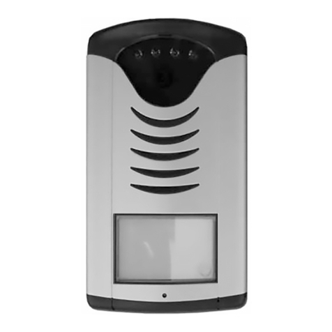
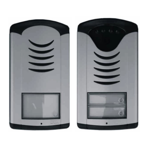
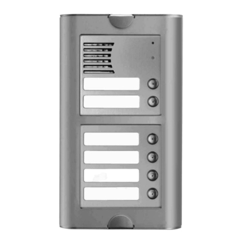
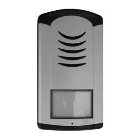
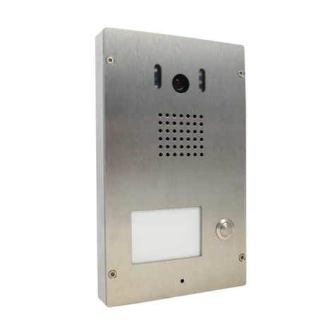
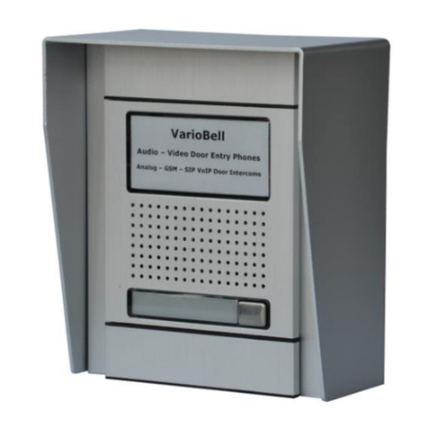
1.4 MODELS OF A-BELL DOORPHONE .................................................................. 9
1.5 PCB SCHEMATICS ........................................................................................ 11
2INSTALLATION............................................................................................... 14
2.1 ASSEMBLY OF A-BELL DOORPHONE ............................................................ 14
2.1.1 Dismounting of the front cover of A-Bell................................................ 14
2.1.2 Wall mounting of A-Bell.......................................................................... 14
2.1.3 Replacement of name plates.................................................................... 15
2.1.4 Demounting and mounting of pushbutton in the front panel................... 15
2.1.5 Closing the front cover of A-Bell ............................................................ 16
2.2 INTERCONNECTION OF TWO MODULES ......................................................... 16
2.3 CONNECTION ............................................................................................... 17
2.4 CAMERA (VERSION /C ONLY)....................................................................... 21
2.5 OTHER ACCESSORIES ................................................................................... 22
2.5.1 TimeRelay ............................................................................................... 22
2.5.2 DistyBox.................................................................................................. 22
2.5.3 Power supply 12V................................................................................... 22
2.5.4 USB programming cable......................................................................... 23
2.5.5 BlackBox................................................................................................. 23
3OPERATING THE UNIVERSAL DOORPHONE......................................... 24
3.1 SIGNALLING OVERVIEW ............................................................................... 24
3.2 VISITOR AT THE DOOR ENTRANCE................................................................ 25
3.1 PERSON INSIDE THE BUILDING...................................................................... 28
3.1.1 Outgoing call .......................................................................................... 28
3.1.2 Incoming call .......................................................................................... 29
4PARAMETERS PROGRAMMING ................................................................ 30
4.1 PROGRAMMING BY PHONE ........................................................................... 30
4.1.1 Entering into programming .................................................................... 30
4.1.2 Parameters programming....................................................................... 30
4.2 PC PROGRAMMING –BELLSET PROGRAM .................................................... 31
5DESCRIPRION OF PROGRAMMABLE PARAMETERS.......................... 32
5.1 DIRECT NUMBERS DIAL –MEMORIES............................................................ 32
5.2 RELAYS........................................................................................................ 33
5.3 BASIC PARAMETERS..................................................................................... 37
5.4 TIME PARAMETERS....................................................................................... 39
