2. SAFETY RULES
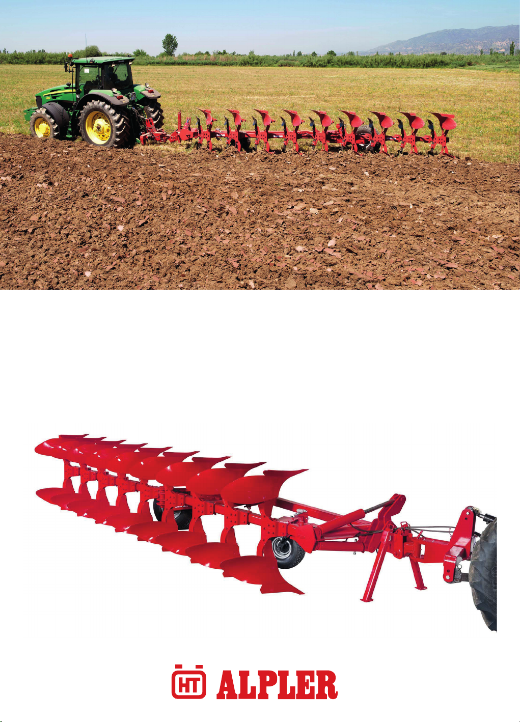
SEMI MOUNTED REVERSIBLE PLOUGH USER GUIDE
4www.alpler.com.tr
2.1. RULES TO BE OBSERVED
1. Before moving, while attaching the plough to tractor please be sure that it is fixed and while detaching the plough be sure there is
no connection left between the leveler and the tractor.
2. Before beginning to drive the tractor, check surroundings area (CHILDREN)!
3. Never stay or allow anyone to stay within the operating area.
4. Never stay in the turning and slew area of the implement!
5. The hydraulic pipes are under pressure!
6. When connecting hydraulic sockets, the pipes must be connected as directed.
7. Always release hydraulic pressure from both tractor and plough before attaching and detaching the plough
8. When connecting hydraulic pipes to the tractor ensure that incorrect connection is avoided. If the connections are reversed, the
opposite function is carried out (e.g. raising/lowering) and there is a risk of accidents.
9. Regularly check the hydraulic pipes and replace the damaged or aged ones with the pipes comply with the technical specifications
as described by ALPLER.
10. Do not operate the equipment with hydraulic oil leaking. Oil is flammable and their presence could present a hazard. Do not check
for leaks with your naked hand! Hydraulic oil escaping at high pressures can penetrate the skin and cause injury. When injured see a
doctor immediately. To check for a hose leak, SHUT the tractor ENGINE OFF and remove all hydraulic pressure. Wear oil impenetrable
gloves and use a cardboard to check for evidence of oil leaks.
11. When working on tires make sure that the implement has been placed on the ground safely and that is secured by chocks against
unintentional rolling
12. After each use, check all bolts and nuts if they need tightening, also for the missing ones, replace them with the original ones.
13. Sitting or standing on the implement during operation or during transport is not permissible.
14. Operator competence. The operator must be well acquainted with the
15. Different functions of the plough and be knowledgeable of how to operate it with safety
16. Ensure that the plough is locked with the correct locking pins onto the three-point linkage on the tractor.
17. Secure the lower link stabilizers on the tractor when the plough is transported on the road.
18. The brake pedals on the tractor must be locked together when driving on the road.
19. All hydraulic connections between tractor and plough must be made in accordance with the instructions given.
20. Always lift the plough prior to the turn-over action.
21. Make sure the lever for the turn-over action is in neutral prior to starting the tractor.
22. Never park the tractor with the plough in an uplifted position.Always use the support leg when parking the plough.
23. Never attempt to clean or adjust the plough during operation.
24. Never touch the gas valve on the accumulator.
25. Adapt the ploughing speed to suit the ground conditions. DRIVE CAREFULLY. Maximum transport speed 25 km/h.
26. The user is responsible for ensuring the implement complies with the law when diriving on public roads.