Page 5
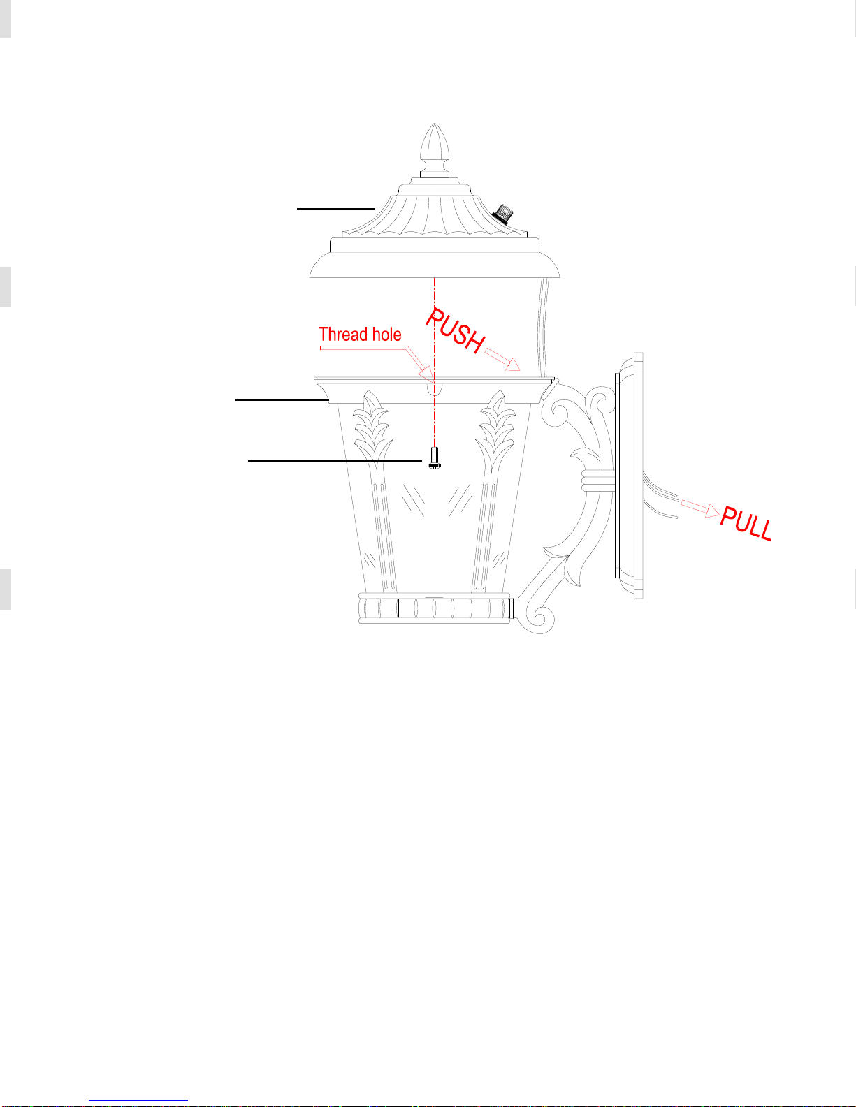
3. Lay the HOOD onto the CAGE and secure it in place using the HOOD
SCREWS, as shown ( Attention:first screw a CAGE SCREW into the thread
hole on the CAGE to connect it with HOOD, then screw the other CAGE
SCREW into the hole without thread on the CAGE to connect it with HOOD).
Simultaneously, pull the fixture wires out the backside of the fixture, as
shown. (Fig. 2)
HOOD
CAGE
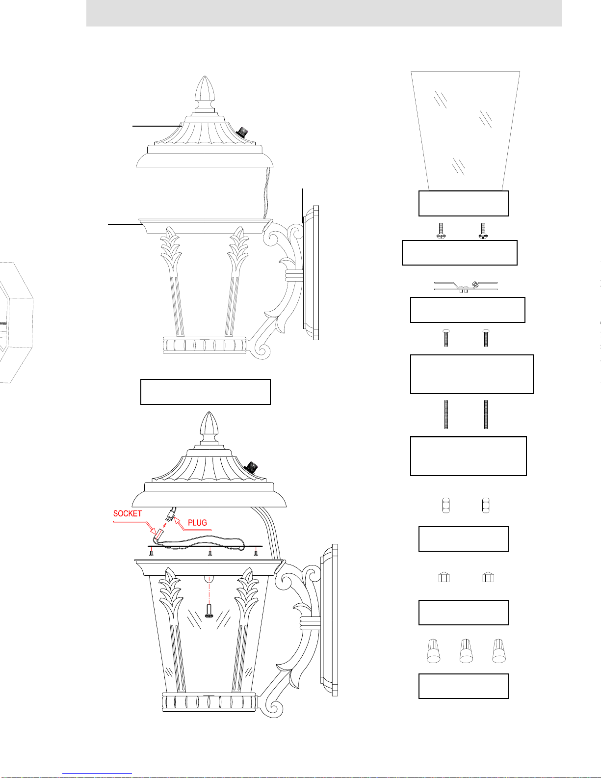
4. Thread the FIXTURE MOUNTING SCREWS into the provided holes of the
MOUNTING BRACKET, as shown. Thread the HEX NUTS onto the
FIXTURE MOUNTING SCREWS, as shown. Do not tighten the HEX NUTS
at this time. (Fig. 3)
5. Pull the power supply wires out from the OUTLET BOX, and attach the
MOUNTING BRACKET to the OUTLET BOX, using the BRACKET
MOUNTING SCREWS. (Fig. 3)
6. Strip approximately ¼” of insulation from each supply wire from the OUTLET
BOX. Raise the MAIN FIXTURE BODY to the wall, bringing the WALL
PLATE close to the OUTLET BOX. Make the following wire connections
using the WIRE NUTS (Fig. 3):
WHITE (NEUTRAL) SUPPLY WRE to WHITE FIXTURE WIRE
BLACK (HOT) SUPPLY WIRE to BLACK FIXTURE WIRE
TWO SUPPLY GROUND WIRES to FIXTURE GROUND WIRE
7. Place the WALLPLATE over the OUTLET BOX, making sure the FIXTURE
Fig. 2
Page 12
CAGE
SCREW
PRECAUCIÓN:
•Se deben realizar todas las conexiones eléctricas de acuerdo con las normas del
código local y el Código Eléctrico Nacional (N.E.C.). Si usted no está familiarizado con
las conexiones eléctricas, contrate los serviciosde un electricistacalificado.
•Suspenda la energía eléctrica en el disyuntor de circuitos antes de instalar el luminario
con el fin de evitar una posible descarga eléctrica.
•Antes limpiar el luminario, suspenda la energía eléctrica y permite que pasen varios
minutos para que el luminario seenfríe.
•Saque la CLAVIJA del PORTAFOCOS cuando vaya a cambiar un foco fundido o
inserto y coloque la CLAVIJA en el PORTAFOCOS cuando ya haya cambiado el foco
nuevo o inserto.
ANTES DE INICIAR:
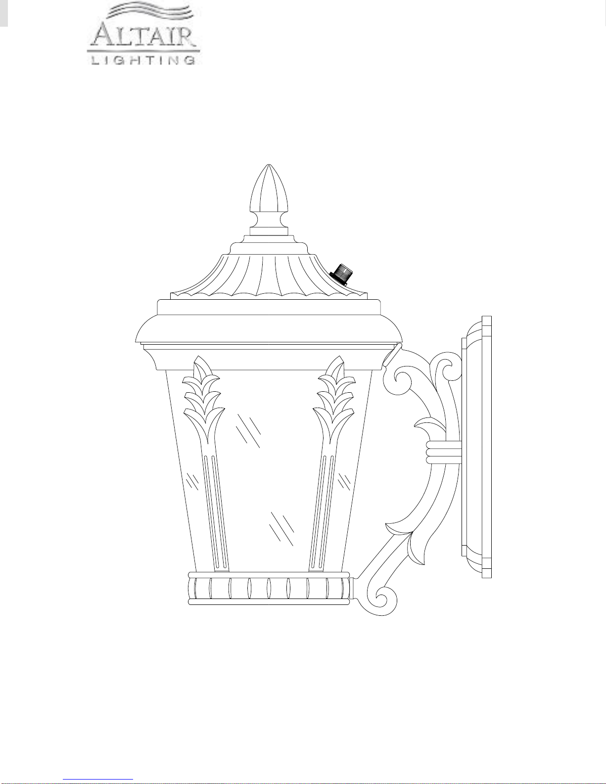
•Este luminario tiene un control de luz con fotocelda que se encuentra en la parte
trasera de la cubierta. Las luces LED se encienden cuando la luz ambiental alrededor
de la fotocelda ha disminuido a un nivel de iluminación nocturna. Las luces
permanecerán encendidas hasta que la la luz ambiental haya regresado a un nivel de
luz de día. Avoid installing the fixture near nighttime light sources, such as street lights
or other Evite instalarl el luminario cerca de fuentes de luces nocturnas, como faroles
públicos u otrosluminarios, ya que pueden evitar que la luz se encienda.
•La CAJA DE DISTRIBUCIÓN que se describe en la siguiente sección no se incluye
con este luminario. Para instalar este luminario se necesita preinstalar una CAJA DE
DISTRIBUCIÓN ESTÁNDAR en el techo, en ellugar de montaje que se haya elegido.
Se necesita pasar cables de alimentación hacia la CAJA DE DISTRIBUCIÓN que
provean 120 VAC de energía. Si no existe una CAJA DE DISTRIBUCIÓN, contacte a
un electricistacalificado para que instale una.
ENSAMBLAJE E INSTALACIÓN:
1. SUSPENDA LA ENERGÍA EN EL DISYUNTOR DE CIRCUITOS.
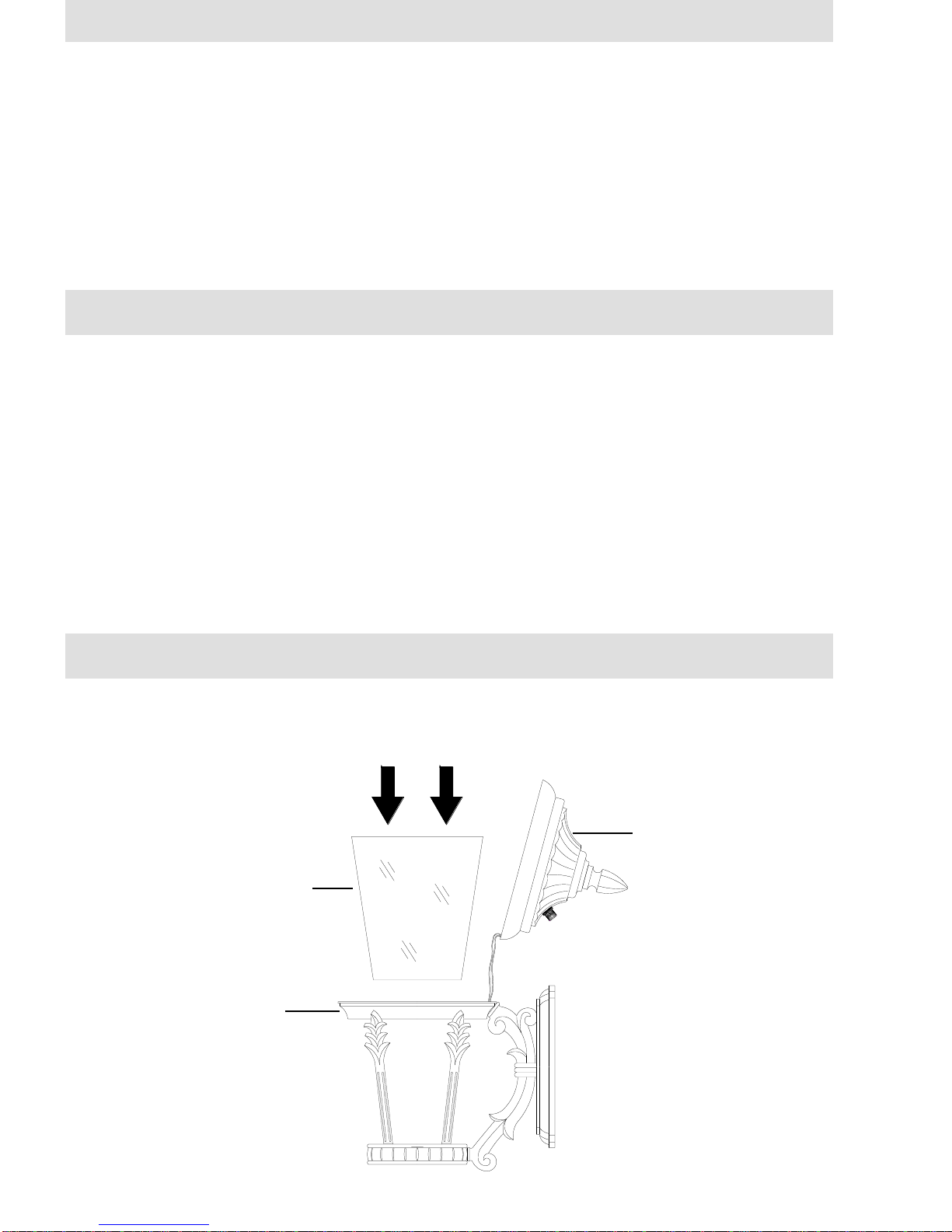
2. Deslice la PANTALLA DE VIDRIO en la JAULA (Fig. 1).
JAULA
PANTALLA
DE VIDRIO
CUBIERTA
Fig. 1