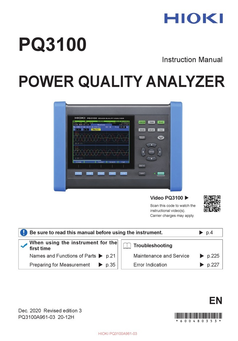
Hioki 3506-10 User manual

3506-10
Instruction Manual
C METER
EN
Sept. 2018 Revised edition 2
3506B981-02 18-09H
3506-10 C METER Instruction Manual


Contents
i
Contents
Introduction.................................................................................1
Verifying Package Contents.......................................................1
Safety Information......................................................................2
Operating Precautions................................................................4
Chapter 1
Overview___________________________________ 7
1.1 Product Overview .........................................................7
1.2 Features .......................................................................7
1.3 Entire Workflow ............................................................9
1.4 Names and Functions of Parts ...................................11
Chapter 2
Measurement Preparations___________________ 17
2.1 Preparation Flowchart ................................................17
2.2 Checking the Power Voltage...................................... 18
2.3 Connecting the Power Cord....................................... 19
2.4 Connecting the Probes and Fixtures.......................... 20
2.5 Turning the Power On and Off ...................................21
Chapter 3
Setting the Measurement Conditions __________ 23
3.1 Pre-Operation Inspection ...........................................23
3.2 Measurement Example ..............................................24
3.3 Setting the Measurement Conditions .........................26
3.3.1 Setting the Display Parameter .......................................26
3.3.2 Measurement Mode ......................................................27
3.3.3 Measurement Frequency ..............................................27
3.3.4 Measurement Signal Level ............................................28
3.3.5 Measurement Speed .....................................................28
3.3.6 Equivalent Circuit Mode ................................................29
3.3.7 Measurement Range .....................................................31
3.3.8 Trigger Signal ................................................................36
1
2
3
3506B981-02

Contents
ii
Chapter 4
Compensate for errors_______________________37
4.1 Open Circuit Compensation and Short Circuit
Compensation ........................................................... 37
4.2 Load Compensation .................................................. 45
4.3 Offset Compensation ................................................. 51
4.4 Self Calibration .......................................................... 55
4.5 Set the Cable Length ................................................. 58
Chapter 5
Judging measurement results ________________59
5.1 Comparator Function ................................................. 59
5.2 BIN Measurement Function ....................................... 74
Chapter 6
Application Functions _______________________91
6.1 Setting the Average Function .................................... 91
6.2 Trigger Delay Setting ................................................. 93
6.3 Using the Contact Check Function ............................ 95
6.3.1 Setting the Low C Reject Function ...............................96
6.3.2 Measurement Level Monitoring Function Settings ........98
6.4 Current Detection Circuit Monitoring Function ......... 100
6.5 Applied Voltage Value Monitoring Function ............. 100
6.6 Using the Frequency Shift Function ........................ 101
6.7 Setting the Display ON/ OFF ................................... 102
6.8 Trigger Synchronous Output Function ..................... 103
6.9 Disable Key Control (Keylock Function) .................. 104
6.10 Save the Measurement Conditions
(Panel Save Function) ............................................. 105
6.11 Load the Measurement Conditions
(Panel Load Function) ............................................. 106
6.12 Setting Beep Tones ................................................. 110
6.12.1 Setting the Beep Tone for Judgment Results of
Comparator and BIN ...................................................110
6.12.2 Setting the Beep Tone for Key Operations .................112
6.13 Switching the displayed item (SUB display) ............ 113
6.14 Performing a System Reset ..................................... 114

Contents
iii
6.15 Printing Function ......................................................115
6.15.1 Preparation Prior to Connecting the Printer ................115
6.15.2 Connection Procedure ................................................118
6.15.3 Printing ........................................................................119
Chapter 7
EXT I/O __________________________________ 121
7.1 About the EXT I/O Connector .................................. 121
7.2 Circuit Configuration and Connections of the EXT I/O
Connector .................................................................123
7.3 About Input and Output Signals ...............................124
7.4 About Measurement Times ......................................127
Chapter 8
Controlling the Unit from a PC _______________ 129
8.1 Outline and Features ................................................129
8.2 Specifications ...........................................................130
8.2.1 RS-232C Specifications ..............................................130
8.2.2 GP-IB Specifications ...................................................131
8.3 Connection and Setting Procedures ........................132
8.3.1 Connecting the RS-232C Cable / GP-IB Cable ...........132
8.3.2 Setting the Interface Communication Conditions ........134
8.4 Remote Function ......................................................137
8.5 Communication Procedure .......................................137
8.6 Things to Know before Beginning Communication ..138
8.6.1 About Message Formats .............................................138
8.6.2 About the Output Queue and Input Buffer ...................143
8.6.3 About the Status Byte Register ...................................144
8.6.4 About Event Registers ................................................146
8.7 Message List ............................................................151
8.7.1 Common Commands ..................................................151
8.7.2 Unique Commands ......................................................152
8.8 Ability to Use Commands by State ...........................165
8.8.1 Common Commands ..................................................165
8.8.2 Unique Commands ......................................................165
8.9 Message Reference .................................................171
8.9.1 Common Commands ..................................................172
8.9.2 Unique Commands ......................................................177
8.9.3 Response Format of Queries for Returning Values ....244
8.10 Initialized Items ........................................................246
4
5
6
7
8
9
10
11
Appendix
Index
Contents
iv
8.11 Creating Programs .................................................. 247
8.11.1 Creation Procedure .....................................................247
8.11.2 Sample Programs .......................................................249
8.12 Troubleshooting the Interface .................................. 251
8.13 Device Document Requirements ............................ 253
Chapter 9
Specifications_____________________________257
9.1 Basic Specifications ................................................. 257
9.2 Accuracy .................................................................. 261
9.3 Measurement Parameters and Arithmetic
Expressions ............................................................. 264
Chapter 10
Maintenance and Service ___________________267
10.1 Inspection, Repair, and Cleaning ............................ 267
10.2 Replacing the Power Fuse ...................................... 269
10.3 Discarding the Unit .................................................. 270
Appendix ______________________________ A1
Appendix 1 Countermeasures Against Incorporation of
External Noise.................................................A1
Appendix 1.1 Countermeasures Against Incorporation of Noise
from the Power Line .....................................................A1
Appendix 1.2 Countermeasures Against Incorporation of Noise
from the Input Line (Types of Probe) ...........................A2
Appendix 2 Measurement of High Impedance ComponentsA3
Appendix 3 Measurement of In-circuit Components...........A4
Appendix 3.1 Measurement Using Guarding Technique ...................A4
Appendix 3.2 Synchronous Measurement .........................................A5
Appendix 4 Mounting the Unit in a Rack ............................A6
Appendix 5 External View...................................................A8
Appendix 6 Options............................................................A9
Appendix 7 Initial Settings Table......................................A11
Index _________________________________Index 1

Introduction
1
Thank you for purchasing the HIOKI “Model 3506-10 C Meter.” To obtain maxi-
mum performance from the unit, please read this manual first, and keep it handy
for future reference.
When you receive the unit, inspect it carefully to ensure that no damage
occurred during shipping. In particular, check the accessories, panel switches,
and connectors. If damage is evident, or if it fails to operate according to the
specifications, contact your dealer or Hioki representative.
This unit 3506-10 C Meter
Accessories • Instruction Manual..............................................................................1
• Power cord.........................................................................................1
• Spare fuse for power supply (according to voltage specification)......1
100 V, 120 V setting : 250 V F 1.0 AL 20 mm x 5 mm dia
220 V, 240 V setting : 250 V F 0.5 AL 20 mm x 5 mm dia
Shipping precautions
Use the original packing materials when transporting the unit, if possible.
Options See Appendix 6 "Options" (p. A9)
Introduction
Verifying Package Contents
Probes, fixture are not supplied with the unit as standard equipment. You
should order them separately, according to requirements.

Safety Information
2
This manual contains information and warnings essential for safe operation of
the unit and for maintaining it in safe operating condition. Before using it, be sure
to carefully read the following safety precautions.
Safety Symbols
The following symbols in this manual indicate the relative importance of cautions
and warnings.
Other Symbols
Safety Information
This instrument is designed to comply with IEC 61010 Safety Standards,
and has been thoroughly tested for safety prior to shipment. However,
mishandling during use could result in injury or death, as well as damage
to the instrument. Using the instrument in a way not described in this
manual may negate the provided safety features. Be certain that you
understand the instructions and precautions in the manual before use.
We disclaim any responsibility for accidents or injuries not resulting
directly from instrument defects.
In the manual, the symbol indicates particularly important
information that the user should read before using the unit.
The symbol printed on the unit indicates that the user should
refer to a corresponding topic in the manual (marked with the
symbol) before using the relevant function.
Indicates AC (Alternating Current).
Indicates a grounding terminal.
Indicates a fuse.
Indicates the ON side of the power switch.
Indicates the OFF side of the power switch.
Indicates that incorrect operation presents a significant haz-
ard that could result in serious injury or death to the user.
Indicates that incorrect operation presents a possibility of
injury to the user or damage to the unit.
Indicates advisory items related to performance or correct
operation of the unit.
Indicates a prohibited action.
See Indicates the location of reference information.
Indicates quick references for operation and remedies for
troubleshooting.
*Indicates that descriptive information is provided below.

Safety Information
3
Measurement Categories
To ensure safe operation of measurement instruments, IEC 61010 establishes
safety standards for various electrical environments, categorized as CAT II to
CAT IV, and called measurement categories. These are defined as follows.
Using a measurement product in an environment designated with a higher-num-
bered category than that for which the product is rated could result in a severe
accident, and must be carefully avoided.
Use of a measurement instrument that is not CAT-rated in CAT II to CAT IV mea-
surement applications could result in a severe accident, and must be carefully
avoided.
Accuracy We define measurement tolerances in terms of rdg. (reading) and dgt. (digit) values,
with the following meanings:
CAT II: Primary electrical circuits in equipment connected to an AC
electrical outlet by a power cord (portable tools, household
appliances, etc.)
CAT II covers directly measuring electrical outlet receptacles.
CAT III: Primary electrical circuits of heavy equipment (fixed installa-
tions) connected directly to the distribution panel, and feeders
from the distribution panel to outlets.
CAT IV: The circuit from the service drop to the service entrance, and
to the power meter and primary overcurrent protection device
(distribution panel).
rdg.
(reading or displayed value) The value currently being measured and
indicated on the measuring instrument.
dgt. (resolution) The smallest displayable unit on a digital
measuring instrument, i.e., the input
value that causes the digital display to
show a "1" as the least-significant digit.

Operating Precautions
4
Follow these precautions to ensure safe operation and to obtain the full benefits
of the various functions.
Preliminary Checks• Before using the unit the first time, verify that it operates normally to ensure
that the no damage occurred during storage or shipping. If you find any dam-
age, contact your dealer or Hioki representative.
• Before using the unit, make sure that the insulation on the probes and cables
is undamaged and that no bare conductors are improperly exposed. Using the
unit in such conditions could cause an electric shock, so contact your dealer
or Hioki representative for replacements.
Operating Temperature and Humidity: 0 to 40°C, 80%RH or less, no condensa-
tion
Storage Temperature and Humidity: -10 to 55°C, 80%RH or less, no condensa-
tion
Accuracy-guaranteed temperature and humidity ranges: 23±5°C, 80%RH
Operating Precautions
Unit Installation
Avoid the following locations that could cause an accident or damage
to the unit.
Exposed to direct sun-
light
Exposed to high tem-
perature
In the presence of cor-
rosive or explosive
gases
Exposed to liquids
Exposed to high hu-
midity or condensa-
tion
Exposed to strong
electromagnetic fields
Near electromagnetic
radiators
Exposed to high lev-
els of particulate dust Subject to vibration

Operating Precautions
5
Installing • Do not install the unit with any side except the bottom facing down.
• Vents must not be obstructed.
OK
10 cm or more
5 cm or more
• Do not allow the instrument to get wet, and do not take measurements
with wet hands. This may cause an electric shock.
• Never modify the unit. Only Hioki service engineers should disassem-
ble or repair the unit. Failure to observe these precautions may result
in fire, electric shock, or injury.
Handling this device
• If anything unusual happens during operation of the unit, turn off the
power switch immediately and contact any HIOKI service facility for
help, advice and service.
• To avoid damage to the unit, protect it from physical shock when transporting
and handling. Be especially careful to avoid physical shock from dropping.
This instrument may cause interference if used in residential areas. Such use
must be avoided unless the user takes special measures to reduce electro-
magnetic emissions to prevent interference to the reception of radio and televi-
sion broadcasts.

Operating Precautions
6
About the guarantee
You should be aware that HIOKI cannot accept any responsibility directly or indi-
rectly if the unit has been incorporated in some other system, or if it is resold to a
third party.
• Before turning the unit on, make sure the supply voltage matches that
indicated on the its power connector. Connection to an improper sup-
ply voltage may damage the unit and present an electrical hazard.
• The power supply voltage for this unit is switchable. To avoid electrical
accidents, check that the voltage selector is set correctly for the supply
voltage you are using.
See Setting Procedure for the Power Voltage : 2.2 "Checking the Power Voltage" (p.
18)
• To avoid electrical accidents and to maintain the safety specifications
of this unit, connect the power cord provided only to a 3-contact (two-
conductor + ground) outlet.
See Connection Procedure : 2.3 "Connecting the Power Cord" (p. 19)
• To avoid shock and short circuits, turn off all power before connecting
probes.
Check the connections carefully in order to avoid any chance of setting
up a short-circuit etc.
Before connection and powering on

1.1 Product Overview
7
9
1
The HIOKI Model 3506-10 C Meter are capacitance meters employing 1 kHz
and 1 MHz frequencies to measure large-value multilayer ceramic capacitors
with constant voltage at high speed and high accuracy. Primary applications
include pass-fail judgment and ranking of capacitors on tape machines and sort-
ers.
These capacitance meters use 1 kHz and 1 MHz measurement frequencies.
The 3506-10 are capable of high-speed measurement: 1.5 ms at FAST.
Capacitors are easily ranked according to C (Capacitance*1) measurement val-
ues into as many as 13 classifications.
Makes pass-fail judgment of components based on C measurement value and D
(dissipation factor*2), or on Q (quality factor*3) measurement value.
Provides superior visibility.
The 3506-10 offers external I/O for sequencing, a standard RS-232C interface,
and a standard GP-IB interface.
Up to 1000 measurement values can be stored in memory.
*1. Capability to store electric charge.
*2. An indicator of capacitor losses.
*3. An indicator of capacitor purity.
Overview Chapter 1
1.1 Product Overview
1.2 Features
Capacitance-specific units
High-speed measurement
Bin sorting function (p. 74)
Comparator function (p. 59)
LED display
Equipped with standard data transfer interfaces (p. 129)
Measurement value memory (p. 232)

1.2 Features
8
The measurement signal can be input to the sample in sync with a trigger.
When using multiple devices, decreases measurement value fluctuation due to
interference by shifting the measuring frequency of each device.
Checks for bad contacts using the Low C reject function and measurement level
monitoring function.
Trigger-synchronous measurement capability (p. 103)
Frequency shift function (p. 101)
Contact check function (p. 95)

1.3 Entire Workflow
9
9
1
Measurement
Preparations See Chapter 2 "Measurement Preparations" (p. 17)
1. Check the power voltage.
2. Connect the power cord.
3. Connect the probes or fixture (option) to the measurement terminals.
4. Turn the power on.
5. Connect the sample.
Pre-Operation
Inspection See 3.1 "Pre-Operation Inspection" (p. 23)
Be sure to perform pre-operation inspection prior to measurement.
Basic Measurement See 3.2 "Measurement Example" (p. 24)
1. Prepare the unit, fixture, and sample.
2. Connect the fixture to the measurement terminals.
3. Set the measurement conditions.
4. Connect the sample to the fixture.
5. Check the measurement results.
End of Measurement 6. Disconnect the sample and turn the power off.
1.3 Entire Workflow

1.3 Entire Workflow
10
Application Functions
Application Measurement
• Countermeasures Against Incorporation of External Noise
See Appendix 1 "Countermeasures Against Incorporation of External Noise" (p. A1)
• Measurement of high impedance components
See Appendix 2 "Measurement of High Impedance Components" (p. A3)
• Measurement of components in circuit networks
See Appendix 3 "Measurement of In-circuit Components" (p. A4)
Function Description Reference
Section
Open and Short circuit
compensation Eliminates measurement errors due to residual impedance. (p. 37)
Load compensation Allows interchangeability between measuring instruments
by measuring a known sample. (p. 45)
Offset compensation Allows interchangeability between measuring instruments
by subtracting the set value from the measurement value. (p. 51)
Cable length compensation Compensates for error caused by extending the measure-
ment cable. (p. 58)
Self calibration Reduces measurement value drift. (p. 55)
Comparator measurement
function Settheupperlimitandlowerlimit valuesandjudge whether
samples pass or fail. (p. 59)
BIN measurement function Set variations of the upper limit and lower limit values and
rank samples accordingly. (p. 74)
Average function Reduces fluctuation of the measurement value by perform-
ing an averaging process of the measurement values. (p. 91)
Trigger delay Providesa reliablemeasurementvalue evenwhentakinga
measurement immediately after connecting to a sample. (p. 93)
Contact check function Discerns whether or not the contact pin and sample are
connected. (p. 95)
Current detection circuit
monitoring function Monitors whether or not current outside the allowed range
is being produced. (p. 100)
Applied voltage monitoring
function Monitors whether or not voltage outside the allowed range
is being produced. (p. 100)
Frequency shift Reduce the differences in measurement values caused by
interference when using multiple 3506-10 units for mea-
surement. (p. 101)
Display Turns the LED display ON/ OFF. (p. 102)
Trigger synchronous output
function Applythe measurementsignal onlyduringmeasurementto
reduce the generation of heat in the sample and decrease
electrode wear. (p. 103)
Key lock function Disable key operations. (p. 104)
Communication function Control the unit from a PC. (p. 129)
Panel save function Save measurement conditions. (p. 105)
Panel load function Load saved measurement conditions (p. 106)
Beep tone Turns ON/ OFF the beep tone for judgment results and key
operations. (p. 110)
System reset Resets device settings. (p. 114)
Printing function Print measurement values. (p. 115)

1.4 Names and Functions of Parts
11
9
1
1.4 Names and Functions of Parts
Front
MAIN Display
Displays the measurement
values of C and D ( or Q).
Displays the MENU items.
Comparator Evaluation
Result Display
Displays evaluation results in
Comparator Mode.
See 5.1 "Comparator Function"
(p. 59)
Setting Condition
Display
Displays current measure-
ment conditions, preset-
tings, and other information.
SUB Display
Displays the limit values of
BIN and comparator.
BIN Judgment Result
Display
Displays judgment results in
BIN mode.
See 5.2 "BIN Measurement
Function" (p. 74)
Error Display
Displays Low C reject and mea-
sured sine wave abnormality errors.
See 6.3.1 "Setting the Low C Reject
Function" (p. 96)
See 6.3.2 "Measurement Level Moni-
toring Function Settings" (p. 98)
Measurement Terminals
There are five measurement terminals:
HCUR The test signal is supplied to this terminal.
HPOT Detected voltage high terminal
LPOT Detected voltage low terminal
LCUR Measurement current detected terminal
GUARD Guard terminal
See 2.4 "Connecting the Probes and Fixtures" (p. 20)
Operating Panel
Use to set measurement
conditions and to make
other settings.
(p. 12)

1.4 Names and Functions of Parts
12
*1 : A decimal point key is only effective when measuring the C offset compensation value.
Operating Panel
Measurement frequency setting
(p. 27)
Measurement signal level setting
(p. 28)
Measurement speed setting
(p. 28)
Equivalent circuit mode
(p. 29)
Measurement range setting
(p. 31)
Open short circuit compensation
(p. 37)
Load compensation setting
(p. 45)
Trigger signal mode setting
(p. 36)
Keypad *1
Used to enter numeric values.
Measurementmode
setting (p. 26)
Comparator measure-
ment function (p. 59)
BIN measurement
function (p. 74)
Manual trigger
(p. 36)
Menu
(p. 14)
Lock/ Local
(p. 104)
Measurement range
setting
(p. 31)
Enter
Arrow keys
Used to change settings
andmovetomenuitems
or digits.

1.4 Names and Functions of Parts
13
9
1
Back
Power Switch
Turns the power on and
off. : Turns the power off.
: Turns the power on.
See 2.5 "Turning the
Power On and Off"
(p. 21)
Voltage
Selectors
Changes the
power voltage.
See 2.2 "Checking
the Power Volt-
age" (p. 18)
Power Inlet
Connect the supplied
power cord.
See 2.3 "Connecting
the Power Cord"
(p. 19)
RS-232C
Connector
Connect an RS-232C
cable.
See Chapter 8 "Control-
ling the Unit from a
PC" (p. 129)
EXT I/O Connector
Inputs external trigger signals and
outputs comparator result signals
and other signals. Supports con-
nection to a PLC (Programmable
Logic Controller).
See 7.1 "About the EXT I/O Con-
nector" (p. 121)
GP-IB
Connector
Connect a GP-IB cable.
See Chapter 8 "Control-
ling the Unit from a
PC" (p. 129)
Stand
Side
Right side
Do not apply heavy downward pressure with the stand extended. The stand
could be damaged.

1.4 Names and Functions of Parts
14
Menu display organization
Displays menu screen
“LoAd_A(C/h)”
(p. 106)
“dELAY”
(p. 93)
“Lo C“
(p. 96)
“bEEP_K “
(p. 112)
“SAVE”
(p. 105)
“Frq.SFt”
(p. 101)
“LEV.ChK“
(p. 98)
“dISP”
(p. 102)
“Ld_tYP“
(p. 106)
“SYnC”
(p. 103)
“JudGE”
(p. 60)
“CAbLE”
(p. 58)
“AVErAG“
(p. 91)
“oFFSEt“
(p. 51)
“bEEP_J”
(p. 110)
Return to Panel Load Function.
(MAIN display area)
Panel Load
Function Panel Save
Function Load
Conditions Average
Function
Trigger Delay Frequency shift
Function Trigger Synchro-
nous Function
Offset
Compensation Low C Reject
Function Level Check
Function Judgment Mode
Beep Tone for
Judgment Results Display
Cable length
Beep Tone for
Key Operations
“Sub.PAr“
(p. 26)
Second
Parameter
Returns to previous screen.
“IF”
(p. 134)
Communication
Conditions
“CALIb”
(p. 55)
Self Calibration
Other manuals for 3506-10
1
Table of contents
Other Hioki Measuring Instrument manuals