4. Connect devices to be powered:
a. For AL1024X220 Power Supply: connect devices to the terminals marked [+ DC -] (Fig. 1, pg. 3)
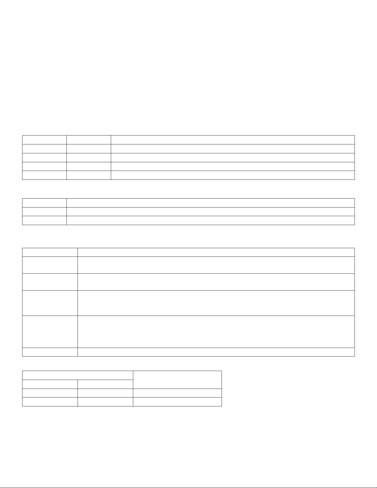
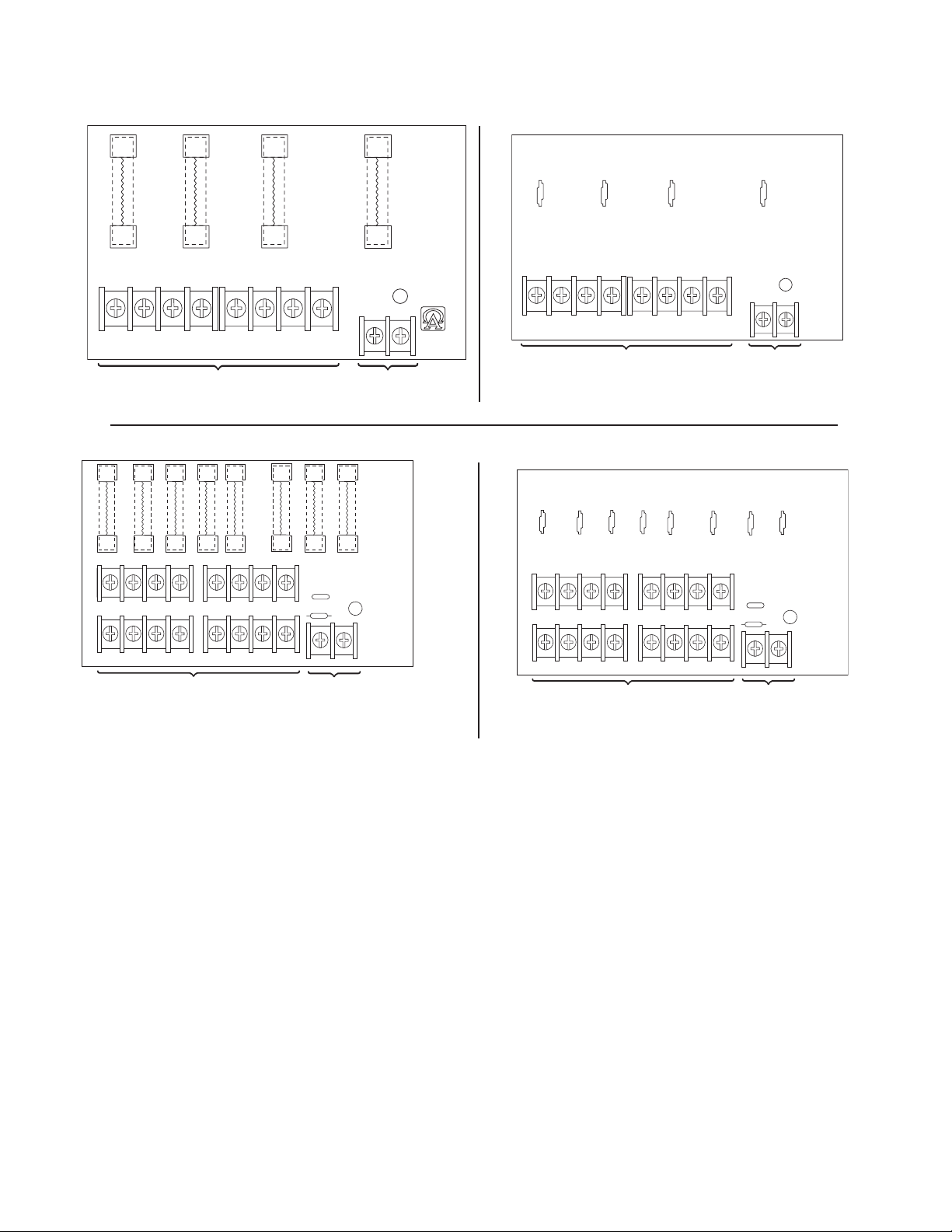
b. For other Power Distribution Models: connect devices to be powered to the terminal pairs 1 to 4 marked
[1P & 1N] through [4P & 4N] (Fig. 2a & 2b, pg. 5) or 1 to 8 marked [1P & 1N] through [8P & 8N]
(Fig. 3a & 3b, pg. 5), carefully observing correct polarity.
5. For Access Control applications batteries are optional. When batteries are not used, a loss of AC will result in
the loss of output voltage. When the use of stand-by batteries is desired, they must be lead acid or gel type.
6. Connect appropriate signaling notification devices to the terminals marked [AC FAIL & BAT FAIL] (Fig. 1, pg. 3)
supervisory relay outputs.
Note: When used in fire alarm, burglar alarm or access control applications, “AC Fail” relay must be used to
provide a visual indication of AC power on.
7. Please ensure that the cover is secured with the provided Key Lock.
LED Diagnostics:
AL1024XB2V - Power Supply Board
Red (DC) Green (AC) Power Supply Status
ON ON Normal operating condition.
ON OFF Loss of AC. Stand-by battery supplying power.
OFF ON No DC output.
OFF OFF Loss of AC. Discharged or no stand-by battery. No DC output.
PD4/PD4CB/PD8/PD8CB - Power Distribution Module
Green (AC) Power Distribution Module Status
ON Normal operating condition.
OFF No Power Output.
Terminal Identification:
AL1024XB2V - Power Supply Board
Terminal Legend Function/Description
L, N Connect 220VAC (working range 198VAC-256VAC), 50/60Hz to these terminals:
L to hot, N to neutral.
+ DC --- 24VDC @ 8A continuous, 10A in alarm non power-limited output.
10A continuous when batteries are not used
AC Fail
NC, C, NO
Indicates loss of AC power, e.g. connect to audible device or alarm panel. Relay normally energized
when AC power is present. Contact rating 1A @ 28VDC. AC or brownout fail is reported within 1
minute of event. To delay reporting for up to 6 hrs., cut “AC delay” jumper and reset power to unit.
Bat Fail
NC, C, NO
Indicates low battery condition, e.g. connect to alarm panel. Relay normally energized when DC
power is present. Contact rating 1A @ 28VDC. A removed battery is reported within 5 minutes.
Battery reconnection is reported within 1 minute.
Low battery threshold: 24VDC output threshold set @ approximately 21VDC.
– BAT +Stand-by battery connections. Maximum charge current 3.6A.
PD4/PD4CB/PD8/PD8CB - Power Distribution Module
Terminal Legend Function/Description
PD4/PD4CB PD8/PD8CB
1P to 4P 1P to 8P Positive DC power outputs
1N to 4N 1N to 8N Negative DC power outputs
- 4 - AL1024X220 series