Installation Instructions:
1. Mount unit in the desired location. Mark and predrill holes in the wall to line up with the top two keyholes in the
enclosure. Install two upper fasteners and screws in the wall with the screw heads protruding. Place the enclosure’s
upper keyholes over the two upper screws, level and secure. Mark the position of the lower two holes. Remove the
enclosure. Drill the lower holes and install the three fasteners. Place the enclosure’s upper keyholes over the two
upper screws. Install the two lower screws and make sure to tighten all screws (Enclosure Dimensions, pg. 7-8).
Secure enclosure to earth ground.
2. Set main switch to the OFF position on all models, (Figs. 1-5, pgs. 4-6).
3. All units are factory set for 24VAC operation.
For 28VAC operation, adjust unit prior to mounting and applying power as follows: Change the wire position so that
the black wire [28V] is connected to the terminal marked [P] and the yellow wire [24V] is connected to the terminal
marked [S].
4. Connect unswitched AC circuit (220VAC, 50/60Hz) as follows: Green branch wire (ground) connects to the terminal
marked , Line connects to the terminal marked [L], and Neutral connects to the terminal marked [N] of the Inlet
Appliance Connector.
5. Measure output voltage before connecting devices. This helps avoiding potential damage.
Terminals marked [1P - 8P] are positive of the same polarity.
CAUTION: Determine the maximum operating voltage of the equipment being powered before adjusting
the output voltage.
6. Connect devices to the terminals marked [1P - 1N] through [4P - 4N] on PD4/PD4CB board (Fig.5, pg. 6)
or the terminals marked [1P - 1N] through [8P - 8N] on PD8/PD8CB board (Figs. 1-3, pgs. 4-5), carefully
observing polarity.
7. Set main switch on all models to the “RESET” (ON) position (Figs. 1-5, pgs. 4-6).
8. Green LED will illuminate when unit is powered.
9. Upon completion of the wiring, secure enclosure door with screws (supplied).
Caution: Equipment to be installed/serviced by authorized/trained personnel only.
Shut branch circuit power before installing/servicing equipment.
WARNING: To reduce the risk of fire or electric shock, do not expose the unit to rain or moisture.
This installation should be made by qualified service personnel and should conform to the National
Electrical Code and all local codes.
Terminal Identification:
PD4/PD4CB - Power Distribution Module
1P - 4P AC output.
1N - 4N AC output.
PD8/PD8CB - Power Distribution Module
1P - 8P AC output.
1N - 8N AC output.
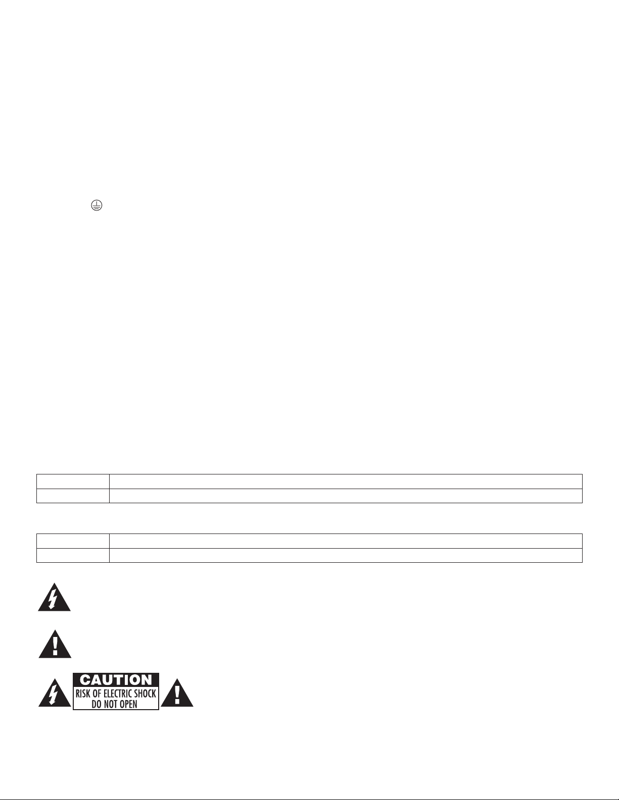
The lightning flash with arrow head symbol within an equilateral triangle is intended to alert the user to the
presence of an insulated DANGEROUS VOLTAGE within the product’s enclosure that may be of
sufficient magnitude to constitute an electric shock.
The exclamation point within an equilateral triangle is intended to alert the user to the presence of important
operating and maintenance (servicing) instructions in the literature accompanying the appliance.
CAUTION: To reduce the risk of electric shock do not open enclosure. There are
no user serviceable parts inside. Refer servicing to qualified service personnel.
ALTV248220series - 3 -
Transformer
underneath
power
distribution
board
Power
Switch
Red
Lead
Black
Lead
Used on PTC Models
(ALTV248300CBM220)
N
COMMON POWER OUTPUTS
P
FUSED POWER OUTPUTS
D1
INPUT
NPS
R1 LED
MAIN FUSE
MAIN FUSE
F1 F2 F3 F4 F5 F6 F7 F8
4A
250V
220VAC Input
50/60 Hz