Alutech CUL01 Instruction manual

CONNECTION
AND OPERATIONAL
MANUAL
Control unit
CUL01
English
2020 www.alutech-group.com


CONNECTION AND OPERATIONAL MANUAL. CONTROL UNIT CUL01 11
CONNECTION AND OPERATIONAL MANUAL
CONTROL UNIT CUL01
DEAR BUYER!
We thank you for purchasing our product
and hope that its quality will conrm that you have made the right choice.
ALUTECH Group of companies has the right to change and complement item construction and this document
without warning.
CONTENTS
1. General provisions and safety measures.............................................................................3
2. Item description ................................................................................................................... 4
3. Specications........................................................................................................................ 4
4. Packaged electronic circuit...................................................................................................5
5. Operation .............................................................................................................................. 8
6. Storage, tranportation and utilisation ............................................................................... 8
7. Warranty................................................................................................................................ 8
8. Certicate of comissioning .................................................................................................. 9
9. Warranty repair................................................................................................................... 10


CONNECTION AND OPERATIONAL MANUAL. CONTROL UNIT CUL01 33
GENERAL PROVISIONS AND SAFETY MEASURES
1. GENERAL PROVISIONS AND SAFETY MEASURES
Y
This manual contains important safety information. Read attentively the information
written below before installation. Keep the manual for further use!
Do not start item installation or operation if you have any questions or you do not understand
something. If necessary, contact the nearest ALUTECH Group of Companies service department
or oce. Follow the safety measures of the existing normative documents and of this manual.
Always follow the safety regulations while working.
Skilled and trained specialists must install, plug in, conduct nal tests, put into operation and
service the item.
Item installation, connection, adjustment and operation in violation of rules is prohibited asit
can lead to breakages, injuries and damage. Item construction elements mustn’t be altered
orchanged and the item mustn’t be misused. Manufacturer and supplier are not responsible
for the damage due to unapproved item alteration, changing or misuse.
Potential risk degree should be evaluated (collision, squeezing, jamming and other hazards).
Itshould decided which additional devices (accessories) are necessary for preventing potential
risks and following the existing safety rules.
The item must not be used in acid, salty or explosive environments.The item must be far enough
from a heat source and open re. If not, the item can be damaged, function improperly, a re
can break out or other dangerous situations can happen.There mustn’t be any foreign objects or
liquids inside during installation or operation, otherwise unplug the item and contact the service
department. Item operation in such a case is dangerous. The control unit must be mounted with
cable inlets pointing downwards so as to prevent water from lling its enclosure.
Turn the power o when carrying out any works (installation, repair, service, cleaning etc.) and
connecting the item. If the switching unit is out of sight, attach the notice plate:‘Do not turnon.
People are working’and take measures to avoid unsanctioned restoring of the supply. Ifthe power
cable (power cord) is damaged, it must be replaced by the manufacturer or service department
specialist. Follow safety measures when using a power cord:
• insert the plug into the socket fully;
• do not pull the cord when you remove the plug from the socket;
• do not a the socket with poor contacts;
• do not touch the plug with wet hands;
• do not damage the power cord, do not twist, bend and stretch it forcibly;
• do not put heavy objects on the power cord and do not place it near hot objects;
• make it easy to reach the socket;
• use only the power cord supplied;
• it is forbidden to use a damaged or defective power cord.
Item installation place must be protected from collisions and impacts; installation surface must
be strong enough. The control unit must be within sight of the equipment, at a height of notless
than 1.5 m. Electrical network must be grounded for safety and security. Make sure the system is
connected and works properly. Electrical network, to which the item is connected, must have a pro-
tection device (16 A circuit breaker). Space between circuit breaker contacts is not less than 3 mm.
Multicore electrical cables parameters (cross section, wire quantity, length etc.) must correspond
to the connection diagram, item power, laying distance, laying method and external conditions.
Electrical cables must be protected from coming into contact with rough and sharp surfaces;
use ribbed, ducting and cable inlets when laying cables. The company has the right to change
the manual and item construction without any reasonable notice maintaining the same func-
tionality. The instruments must be fault-free and correspond to the existing safety regulations,
standards and instructions.

CONNECTION AND OPERATIONAL MANUAL. CONTROL UNIT CUL0144
ITEM DESCRIPTION
The company does not control item installation and automation devices, their service and opera-
tion, and therefore it is not responsible for installation, operation and technical service safety.
The recommendations written above should serve as an example because system installation
locations can be dierent. The installer is responsible for making the most appropriate decision.
The installer is responsible for work on the whole system. He must follow the existing norms and
standards (e.g., DIN1986, EN12050, EN1398) in his work. He is also responsible for management
of technical documents which are delivered together with equipment.
The contents of this manual cannot be used as grounds for legal challenges.
2. ITEM DESCRIPTION
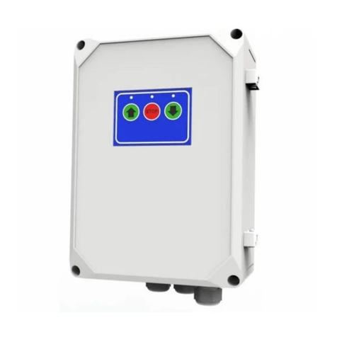
The control unit is used for SL dock leveller with swing lip with 1-valve hydraulic unit. There is
a line circuit breaker 1and control button 2on the cover of the control unit body (pic.1). The
dimensions for mounting are also shown on pic.1 in millimetres.
1
2
190
280
254
180
Pic. 1. CUL01 control unit
3. SPECIFICATIONS
The following specications are true if the ambient temperature is 20 (±5)ºС.
Table1. Specications
Parameters Nominal values
Power supply voltage 3~/400 V or 230 V
Network frequency, Hz 50
Electric motor capacity, kW <1.2
Power consumption in stand-by mode, W <5
Operating supply voltage, W 24 DC
Wires connected to the sockets cross section, mm2max 2.5
Ingress protection rating IP54 (professional installation)
Operating temperatures range, ºС −25…+40
Power cord length/wire cross section not less than 1 m/1.5 m2

CONNECTION AND OPERATIONAL MANUAL. CONTROL UNIT CUL01 55
PACKAGED ELECTRONIC CIRCUIT
4. PACKAGED ELECTRONIC CIRCUIT
A control unit body has a packaged electronic circuit installed to which electrical devices are
connected (pic.2). See the circuit elements list in Table 2.
J11 J4
J3
J9
HPT-IN
WVU L1 L2 L3 N
PE PE
HPT-OUT
L1 L2 L3
J8
MOTOR
REL1
U8
U9
U10
J7
230V
400V
U11
U12
REL2
J10
24V+
Vent+
Sens
GND
GND
J1
NPN
PNP
J12
LED1
J2
2A-T
3×6,3A-T
Pic. 2. Packaged electronic circuit

CONNECTION AND OPERATIONAL MANUAL. CONTROL UNIT CUL0166
PACKAGED ELECTRONIC CIRCUIT
Table2. Circuit elements list
Element Description
U8 Safety device T6.3А
ATTENTION: Use safety devices lled with glass sand!
U9
U10
U11 Transformer
U12 2А safety device
REL1 Relay
REL2
LED1 The LED which signals the valve’s operational status.
It is on if power voltage is supplied to the valve
J1 Jumper for selection of safety sensor type: PNP or NPN (transistor output)
J2 Control button2 adapter (pic.1)
J3 Network adapter (pic.3)
J4 Protection grounding adapter
J7 Jumper adapter depending on the supply voltage.
If supply voltage is 400 V, the jumper must be installed as in pic.2
J8 Line circuit breaker1adapters (pic.1, pic.2).
The plug of 015 3P+N+E 16A/6h type is used for network connection.
The socket must be of the same type for the plug using it
J9
J10
The adapter of a hydraulic unit valve (pic.5) and sectional doors position
sensor (pic.6). Security sensor supply voltage is 24V DC. If the security sensor
has signaled (sectional doors are closed), the hydraulic unit electric motor
must be turned o and the platform must be blocked
J11 The adapter of a hydraulic unit electric motor (pic.4) and stop-motion
sensor(NC)
J12 LED1 jumper. The LED will be on if the jumper is installed.
If the jumper is removed, the LED is o.
YIf security sensors are not plugged in (J10 and J11 adapters), jumpers must be installed
(pic.2). If a security sensor is plugged in, remove the jumper.

CONNECTION AND OPERATIONAL MANUAL. CONTROL UNIT CUL01 77
PACKAGED ELECTRONIC CIRCUIT
HPT-OUT
L1 L2 L3
J8
J3
J9
HPT-IN
L1 L2 L3 N
PE PE
3Р+N+PЕ / type 015 /16A-6h
J4
L1 L2 L3
Pic. 3. Network and line circuit breaker connection
J11
J4
WV UPE PE
M
3~
Pic. 4. Electric motor connection
YIf the platform does not move (travel direction does not coincide with the required one)
when the control button 2 is pushed, two electric motor phase wires are to change their
positions.
J10
24V
+
Vent+
Sens
GND
GND
J10
24V+
Vent+
Sens
GN
D
GN
D
BN
BK
BU
BN — коричневый
BK — черный
BU — синий
Pic. 5. Valve connection Pic. 6. Security sensor connection
(sectional doors position sensor)

CONNECTION AND OPERATIONAL MANUAL. CONTROL UNIT CUL0188
OPERATION
5. OPERATION
In order to supply power to the circuit put the line circuit breaker 1(pic.1) into I position. 0cir-
cuitbreaker position—OFF.
Dock leveller operation:
The platform is lifted if the key2 (pic.2) is pressed and held down (pic.2). The lip is swung into the
extreme top position. When the lip is lifted completely by making a single plane with the core
platform part release the key. The platform will start lowering automatically into an intermediate
position until reaching the vehicle loading level.
Platform return to its original position:
In order to return the platform to its original position press and hold down the key2(pic.1)
until the lip is folded down. Release the key, and the platform will return automatically to its
original position. Control unit must be serviced as part of the dock leveller strictly according to
the existing normative documents.
6. STORAGE, TRANPORTATION AND UTILISATION
Items must be stored packaged in a closed dry room. Avoid precipitation and direct sunlight.
Shelf life is 3years from the date of manufacture. Transportation is possible by all types of
enclosed and roofed land transport tted with restraints to prevent impacts and movement
whilst inside the vehicle.
The item is utilised in accordance with laws and regulations on recycling and utilisation
which are in force in the country of the customer. The item does not contain precious
metals and substances dangerous for life, health and environment.
YThe package must be utilised in accordance with existing legislation.
7. WARRANTY
The item works well if it is stored, transported, adjusted and run according to the existing rules;
if installation and technical service are provided by the organisation specialising in automation
systems and responsible for installing and technical service.
Warranty period is 2 years and it starts from the date of item transfer to the applicant or from the
manufacture date if the date of transfer is unknown. During the warranty period, all breakages
for which the manufacturer is responsible are repaired by the warranty service department.
Note: parts replaced under warranty belong to the service department which has repaired the item.
Item warranty is not valid in case of:
• breaking the item storage, transport, operation and installation regulations;
• when the item is installed, adjusted, repaired, reinstalled or remade by unauthorised persons;
• item becomes damaged because supply network operates unstably or network
parameters do not comply with manufacturer’s values;
• item damage because of water ingress;
• force majeure (fire, lightning, flood, earthquake or other natural disasters);
• when the item construction has been broken by customers or third parties;
• breakages and defects when there is no planned service maintenance and inspection;
• absence of a completed (filled-in) manual.
More information about service departments: http://www.alutech-group.com/feedback/service/

CONNECTION AND OPERATIONAL MANUAL. CONTROL UNIT CUL01 99
CERTIFICATE OF COMISSIONING
8. CERTIFICATE OF COMISSIONING
Serial number and date of manufacture���������������������������������������������
data from the item label
Organisation responsible for installation and technical service
������������������������������������������������������������������������������
������������������������������������������������������������������������������
name, address and telephone
Date of installation: ����������������������������������������
LS date, month, year
Responsible for installation����������������������������������
signature
��������������������������������������������������������
print name
Consumer (Applicant) have checked the completeness of the set, is aquianted and agrees with
warranty conditions and terms, has no complaints about the item design. The item is installed
and adjusted in accordance with the specied requirements and is suitable for operation. Safety
and operational instruction has been conducted.
Applicant (consumer)������������������������������������������������������������
������������������������������������������������������������������������������
name, address and telephone
Applicant’s (customer’s) signature ����������������������������
signature
��������������������������������������������������������
print name

CONNECTION AND OPERATIONAL MANUAL. CONTROL UNIT CUL011010
WARRANTY REPAIR
9. WARRANTY REPAIR
Repair organisation �������������������������������������������������������������
List of repair works��������������������������������������������������������������
������������������������������������������������������������������������������
������������������������������������������������������������������������������
Date of repair ������������������������������������������������������������������
LS
Responsible for repair ��������������������������������������
signature
��������������������������������������������������������
print name
- - - - - - - - - - - - - - - - - - - - - - - - - - - - - - - - - - - - - - - - - - - - - - - - - - - - - - - - - - - - - - - - - - - - - - - - - - -
Repair organisation �������������������������������������������������������������
List of repair works �������������������������������������������������������������
������������������������������������������������������������������������������
������������������������������������������������������������������������������
Date of repair ������������������������������������������������������������������
LS Responsible for repair �������������������������������
signature
�������������������������������������������������
print name

CONNECTION AND OPERATIONAL MANUAL. CONTROL UNIT CUL01 1111
COMMENTS
COMMENTS
������������������������������������������������������������������������������
������������������������������������������������������������������������������
������������������������������������������������������������������������������
������������������������������������������������������������������������������
������������������������������������������������������������������������������
������������������������������������������������������������������������������
������������������������������������������������������������������������������
������������������������������������������������������������������������������
������������������������������������������������������������������������������
������������������������������������������������������������������������������
������������������������������������������������������������������������������
������������������������������������������������������������������������������
������������������������������������������������������������������������������
������������������������������������������������������������������������������
������������������������������������������������������������������������������
������������������������������������������������������������������������������
������������������������������������������������������������������������������
������������������������������������������������������������������������������
������������������������������������������������������������������������������
������������������������������������������������������������������������������
������������������������������������������������������������������������������
������������������������������������������������������������������������������
������������������������������������������������������������������������������
������������������������������������������������������������������������������
������������������������������������������������������������������������������
������������������������������������������������������������������������������
������������������������������������������������������������������������������
������������������������������������������������������������������������������
������������������������������������������������������������������������������
������������������������������������������������������������������������������


Art. R7090126
03.2018
10, Selitskogo str.
220075, Minsk, Republic of Belarus
Tel. +375 (17) 330 11 00
Fax +375 (17) 330 11 01
www.alutech-group.com
Table of contents
Other Alutech Control Unit manuals
Popular Control Unit manuals by other brands

Danfoss
Danfoss ADAP-KOOL AK-CT 200A user guide

Pfeiffer Vacuum
Pfeiffer Vacuum UDV 146 operating instructions

Advantech
Advantech PCM-3347 Series user manual

Allen-Bradley
Allen-Bradley ArmorBlock 1732E-OB16M12R installation instructions

metso automation
metso automation Wafer-Sphere C Installation maintenance and operating instructions

ICP DAS USA
ICP DAS USA PET-7261 quick start guide

Mitsubishi Electric
Mitsubishi Electric MELSEC Q Series user manual

Motorline
Motorline MC15SC User& installer's manual

Emerson
Emerson Keystone 990 Installation, operation and maintenance guide

Sharkoon
Sharkoon Xtatic Digital Operation manual

Beastx
Beastx Nanobeast instruction manual

EES
EES MFW Series operating instructions