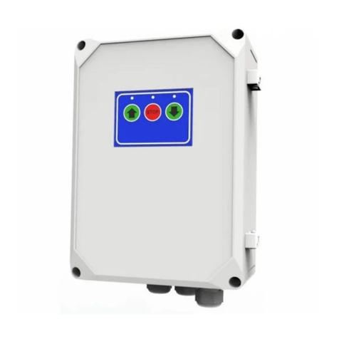
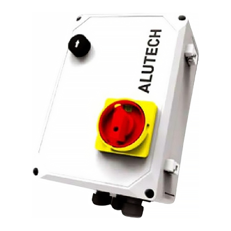
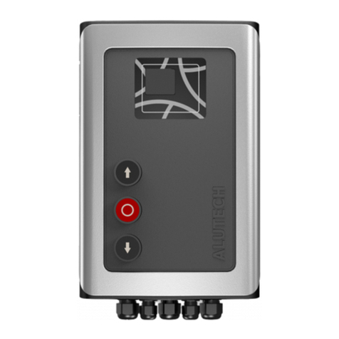
Alutech CU-TR400-868 User manual

11CONTROL UNITS UTR230868/UTR400868
ENGLISH
1. Safety rules and warnings ................................................2
1.1. General .................................................................... 2
1.2. During installation ............................................................ 2
1.3. During operation ............................................................. 3
2. Product description .....................................................4
2.1. Delivery kit.................................................................. 4
2.2. Specications................................................................ 5
3. Preparation for installation ...............................................5
4. Installation ...........................................................6
5. Electrical connections ...................................................6
5.1. Network and electric drive connections ............................................. 6
5.2. Connection of switches/drive encoder ............................................. 7
5.3. Connection of additional devices.................................................. 7
6. Settings ..............................................................9
6.1. Setting the end position of doors ................................................. 10
6.2. Radio control setting........................................................... 12
6.3. Setting operation parameters .................................................... 19
6.4. Reset to factory settings ........................................................ 26
6.5. Cycle counter data ............................................................ 27
7. Inscription ........................................................... 28
8. Verication of operation and commissioning ................................ 30
9. Maintenance service ................................................... 31
10. Malfunctions and recommendations for their elimination ....................... 32
11. Storage, transportation, disposal .......................................... 34
12. Warranty obligations ................................................... 34
13. Commissioning certicate ............................................... 35
14. Information on the performed works....................................... 36
15. Information on repairs during warranty period ............................... 37
CONTENTS

CONTROL UNITS UTR230868/UTR40086822
SAFETY RULES AND WARNINGS
1. SAFETY RULES AND WARNINGS
1.1 GENERAL
Y
ATTENTION! This manual contains important safety information. Please read all information
below carefully before installation and operation. Keep this manual for future reference!
Follow the safety and labor protection rules regulated by current normative documents and this
manual. Failure to comply with the rules can lead to serious damage, serious injury andinjury,
death. Observe the requirements of standards regarding the design, installation and door op-
eration (EN12604, EN12453), as well as other possible local rules and regulations.
YATTENTION! Installation, connections, adjustment, commissioning, maintenance, dismantling
and disposal of the product must be carried out by qualied (professional) and trained specialists
(EN12635), competent and specialized organizations. Installation, programming, adjustment and
operation of the product in violation of the requirements of this manual is not allowed, asthis
can lead to damage and personal injury.
Do not start installation and operation of the product if you have any questions or if you do not
understand anything. If necessary, contact your nearest ALUTECH service or oce.
It is not allowed to make changes to any elements of the product design and use the product for
other purposes. The manufacturer is not responsible for any damage caused by unauthorized
changes to the product or misuse.When carrying out any work (installation, repair, maintenance,
cleaning, etc.) and electrical connections, disconnect the power circuit. If the switching device is
out of sight, attach a plate:‘Do not switch on. People are working’and take measures to eliminate
the possibility of erroneous voltage supply.
The manufacturer and supplier do not exercise direct control over the installation of the product,
and are not responsible for the safety of installation, operation and maintenance of the product.
The company reserves the right to make changes to this manual and product design without
prior notice, while maintaining the same functionality and purpose.The contents of this manual
can not serve the basis for legal claims.
1.2 DURING INSTALLATION
Y
ATTENTION!The condition of all components and materials must be suitablefor use and comply
with applicableregulatory documents.The used tools and materials must be in full working order
and comply with applicablesafety regulations, standards and instructions.
Make sure that the product is used correctly (section ‘2. Product description’). The installation
location of the product must comply with the declared temperature operating range indicated
on the product label.
Remove all unnecessary parts (cables, ropes, angles, chains, etc.) before installation and turn o
all unnecessary equipment.
Make sure that there is enough space for installation and operation of the product.
Make sure that the drive system devices are protected against accidental impact by passing
vehicle. Otherwise, provide protective equipment (fences).
The surfaces of the installation locations of the devices must be durableand must be used as
a reliableand rigid support, eliminating vibration. Otherwise, take measures to strengthen the
installation locations. The control unit and other stationary control devices must be located

CONTROL UNITS UTR230868/UTR400868 33
SAFETY RULES AND WARNINGS
within the visibility of doors at a height of not less than 1.5 meters and at a safe distance from
moving elements. Control devices should not be publicly available.
In the case of using radio remote controls, make sure that the installation location of the control
unit provides high-quality radio signal reception (there are no shielding and reective surfaces,
other sources of radio emission). Otherwise, take measures to ensure the operation of the radio
control (for example, the use of an external antenna).
The electrical network must be equipped with protective earth connection. Make sure that
the earth connection system is correctly designed and connected. The section of the electrical
network to which the product is connected must be equipped with asuitableshort circuit
protection device (circuit breaker or other equivalent device) in accordance with the features
of the network and the product.
The electrical cables of the control and safety devices must be laid separately from the mains
voltage cables. Cables should be protected from contact with any rough and sharp surfaces;
use corrugations, pipes and cableentries when laying cables. For electrical connection of drive
system components, use double insulated copper multi-strand cable.The features of used electric
cables (cross-section, number of wires, length, etc.) must correspond to the connection diagram,
device power, laying distance, laying method, and external conditions.
It is necessary to provide protection against crushing, impact, trapping, tightening and other
hazards (EN12604, EN12453), it could be achieved by the installation of safety devices; instal-
lation of protective designs; maintaining safe distances and clearances, setting up the product.
The operation of safety devices such as a safety edge or photo line (light curtain) must comply
with the requirements of standards (EN12978, EN13849). Ensure safe operation of doors with
automatic drive.
When operating outside the doors visibility zone or when automatic closing of doors is activated
in the settings, photocells (or an equivalent safety device) must be installed.
The product and the entire drive system can be nally put into operation only when it’s conrmed
that the door and the structure its built-in correspond to the requirements and directives of the
existing local rules and regulations.
1.3 DURING OPERATION
Y
ATTENTION! The product should not be used by children or persons with limited physical,
sensory or mental abilities, as well as persons with insucient experience and knowledge, who
have not been instructed about the use.
Do not let children play with control devices. Keep remote controls out of the reach of children.
Never grab onto moving doors or moving parts.
Make sure that there are no people, animals, vehicles or objects in the danger area before set-
ting the doors in motion. Observe the movement of doors until they open or close completely.
Passage is allowed when the doors are open, have completely stopped and motionless. Passage
is forbidden when the doors are moving.
Do not stay (stop) in the zone of door movement. Automatic doors may be set in motion at an
unexpected moment!
Inspect the drive system and doors regularly, in particular verify cables, springs, and mounting
hardware for signs of wear, damage, or imbalance. It is forbidden to use a product requiring
repair or adjustment, as a defect in installation and operation can lead to personal injury or
damage to the product.

CONTROL UNITS UTR230868/UTR40086844
PRODUCT DESCRIPTION
Monthly verify the operation of safety devices (safety edge, photocells, STOP devices, stopping
the movement and others). Malfunction and faulty operation of safety devices can result in injury.
The product is not intended for use in acidic, salty or explosive atmospheres, on evacuation
routes and emergency exits.
Foreign objects, materials from construction works, water or other liquid should not be inside
the product and other electrical devices of the drive system. Operation of equipment in this
condition is prohibited.
Sources of heat and open ames must be removed a sucient distance from the product.
Violation of this requirement can lead to damage to the product, cause its malfunction, lead to
dangerous situations.
The product as part of the drive system must be serviced regularly to ensure ecient and safe
operation. Maintenance and repairs must be documented by the persons performing them, and
the owner must keep these documents.
Do not use the product if repairs are required!
2. PRODUCT DESCRIPTION
Control units CU-TR series are designed to control and manage the devices of the drive system
of industrial sectional doors. Direct application is operation control of drives TR series*:
CU-TR230-868: TR-3531-230, TR-5024-230, TR-3531-230E, TR-5020-230E, TR-5024-230E
CU-TR400-868: TR-5024-400, TR-10024-400, TR-13018-400, TR-5013-400E, TR-5020-400E,
TR-5024-400E, TR-10024-400E, TR-13018-400E, TR-13012-400E
The drive system is a set of devices (electric drive, electric control unit, safety, control, alarm
devices, sensors) that control the door movement and ensure the safe operation of doors.
2.1 DELIVERY KIT
The delivery kit is shown in g.1.
YAfter receiving the product, make sure that the kit is complete and that the kit components are
not visibly damaged. In case of discrepancies, contact the supplier.
* Drives with encoder are with the designation E.
Drives with mechanical end position switches are without designation E.

CONTROL UNITS UTR230868/UTR400868 55
PREPARATION FOR INSTALLATION
2.2 SPECIFICATIONS
Table1
FEATURE CUTR230868 CUTR400868
Supply voltage 230V ± 10% ~ 400V ± 10% 3N~
Network frequency, Hz 50
Maximum drive power, kW 1 1.5
Maximum power consumption in standby mode
(without additional devices), W 3 4
Power supply for additional devices 12V DC/max.150 mA
24 V DC/max.250 mA
Cross section of wires connected to connectors max.2.5 mm
Radio control 868.35MHz±0.15MHz/dynamic code/
maximum of 32 remotes
Protection degree IP65 (professional installation)
Operating temperature range,°C −30…+65
Gross weight, kg 2.7 2.9
Overall and mounting dimensions of the control unit are in g.2, 3. Fig.3 shows the dimensions if
installation is on the unit body of external xings.
Service life is 8 years, but not more than 100,000 full cycles when performing maintenance, in-
stallation and operation rules.
3. PREPARATION FOR INSTALLATION
1. Read section‘1. Safety rules and warnings’. Make sure that all rules and requirements are
followed and fulfilled.
2. Determine the location, where each drive system device will be installed. An example of
a typical scheme of automation of sectional balanced industrial doors with a wicket is in
fig.4. Determine the installation locations of the control devices together with the user
(owner).
3. Determine which devices (for safety, control, signaling, etc.) and accessories (electrical
cables, cablechannels, connectors, junction boxes, fasteners, etc.) that are not included in
the complete kit must be purchased separately. Identify the electrical circuit, according to
which all drive devices will be connected.
Y
ATTENTION! Depending on the conditions and doors operational mode, identify corresponding
safety devices, which are dened by safety regulations of your country or EN12453 standard in
accordance with safety type (minimal safety level). When delivered, the product is designed for
use in manual mode (tab.13, setting P3-F1).
4. Lay electrical cables in accordance with current regulations to the locations where the
drive system devices are to be installed.
5. Install the required number of cableentries at the bottom of the control unit body
(PG13.5 and PG9 entries are included in the complete kit). Previously drill apertures in the
indicated places of the unit body (when the cover is closed) according to dimensions of
the cableentry or cut them out (for example, with a sharp screwdriver in several places
ofone aperture). Do it carefully.

CONTROL UNITS UTR230868/UTR40086866
INSTALLATION
4. INSTALLATION
Install the control unit on a vertical surface within the visibility of doors (next to doors) at aheight
of at least 1.5m (g.4) at a safe distance from the moving elements of doors. It is recommended
to install the control unit relative to doors on the installation side of drive. The cableentries of
the control unit must face down. The installation location of the control unit must ensure the
opening (turn to the left) of the cover of the unit body.
Y
Type of fasteners (dowels, self-tapping screws, etc.), install depending on the material and
thickness of the surface (wall) on which the control unit is installed. For xing the unit, there
are four dowels with screw5in the kit (g.1). If they do not t, then purchase the required
fasteners yourself.
There are two ways to install the control unit:
OPTION 1. Installation with four hidden mounting apertures of the unit (g.2). To access the
apertures, it is necessary to open the cover of the unit body by unscrewing four screws (g.5),
previously carefully removing the cover frame. To mark apertures on the surface, use template7
(g.1) from the unit kit.
OPTION 2. Installation with four external fasteners (g.3). On the base of the control unit body,
use screws4(g.1) to install at the required mounting angle3(g.1).Then mark the xing points
on the mounting surface and x the unit.
5. ELECTRICAL CONNECTIONS
Y
ATTENTION! For electrical connections make sure that the mains power is disconnected (circuit
breaker of the mains power is o)!
Follow electrical safety regulations!
Y
Use a puller to remove the connectors. Gently pull with the puller by the connector (g.6),
ifnecessary, in several locations along the length of the connector.
The door control buttons and the display window are located on the unit body cover (g.7). The
buttons are connected to the electronic module of the unit by the manufacturer.
5.1 NETWORK AND ELECTRIC DRIVE CONNECTIONS
The network connection is performed to connector 1 of the unit (CU-TR230-868—g. 8,
CU-TR400-868—g.9). Lis phase (phases), Nis neutral. Protective earth is connected to
connector2.
Y
When connecting to the network, there should be provided a device disconnecting all poles from
the network (for instance, automatic circuit breaker), which ensures full disconnection under
conditions of over-voltage category III. The device should be installed in accordance with Electrical
Installations Code and located at easily accessible place, at convenient and safe height (1.5-1.9 m).
The electric drive is connected to connector10.
The connection of connectors4and 12 is performed by the manufacturer:
• Network and electric drive TP series (230V~) connection to the CU-TR230-868 control unit is
presented in fig.10.
• Network and electric drive TP series (400V 3~) connection to the CU-TR400-868 control unit
is presented in fig.11.

CONTROL UNITS UTR230868/UTR400868 77
ELECTRICAL CONNECTIONS
YWhen connecting the electric drive to the control unit, rst read the section on electrical con-
nections of the drive manual. Identify the required cableand the wire marking of cablesupplied
with the drive.
5.2 CONNECTION OF SWITCHES/DRIVE ENCODER
Connection a driver TR series with mechanical switches is shown in g.12. Limitswitches(B) of
drive are connected to OP.L and CL.L contacts. Function switches (A) ofdrive are connected
to 5.L and P. L contacts, which must be used when switching on in the unit menu the settings
P5–F7 and P5–F1 (tab.13), respectively. Contact P. L is not used in the CU-TR400-868 control unit!
YMake sure that connector 18 is installed with a crossbar (is included in complete kit).
Ifthere is no connector with a crossbar, connect a crossbar between the IN_S and O_S
contacts of connector 16. When connecting the electric drive to the control unit, rst
read the section on electrical connections of the drive manual. Identify the required
cableand the wire marking of cablesupplied with the drive.
Connection a drive TR series with encoder is shown in g.13. Connection is performed using
the cableprovided with the drive.
Y
ATTENTION!When using a drive with encoder, make sure that there are no connections
(crossbars, switches) to connector 16 of the unit.
5.3 CONNECTION OF ADDITIONAL DEVICES
Y
When operating, installing and connecting additional electrical devices (accessories), the manuals
supplied with these devices must be observed. Incorrect connection may result in malfunction
of the product. Use additional devices (accessories) oered by ALUTECH Company and with the
required characteristics. ALUTECH Company is not responsible for the operation of the drive
system when using additional devices produced by other manufacturers.
Designation of connectors and connector contacts in tab.2:
CU-TR230-868—g.8, CU-TR400-868—g.9.
Table2
CONNECTOR CONTACT DESCRIPTION
20
A
The input of the‘OPEN/CLOSE’ control devices (g.14, ALARM) with anormally
open contact (NO). Depending on the direction selected in the settings (tab.13,
P7–F5), actuation the input will open or close the doors. During the operation
(closure) of the input, all other control commands are not executed
OP
The input of the control devices‘Open’(g.14, OPEN) with a normally open
contact (NO). The control command OPEN is executed when actuation with the
factory settings. The logic of operation depends on the settings (tab.13, P3–F8)
GND General contact
CL The input of the control devices‘Close’ (g.14, CLOSE) with a normally open
contact (NO). The control command CLOSE is executed when actuation
SBS
The input of the control devices‘Step by step’ (g.14, STEP BY STEP) with a
normally open contact (NO). The control command STEP BY STEP is executed
when actuation with the factory settings. The logic of operation depends on
the settings (tab.13, P3–F8)
P
The input of the control devices‘Pedestrian’(g.14, PEDESTRIAN) with anormally
open contact (NO). With the doors fully closed (in the nal closing position), the
actuation will open the doors during the time set in the setting (tab.13, P1–F9)

CONTROL UNITS UTR230868/UTR40086888
ELECTRICAL CONNECTIONS
CONNECTOR CONTACT DESCRIPTION
20
S
The input of the control devices‘Stop’ (g.14, STOP) with a normally closed
contact (NC). Actuation will immediately stop the door movement or block the
start of the door movement
+24V Power output of additional devices. Supply voltage 24V DC (DC)/max.250 mA
+12V Power output of additional devices. Supply voltage 12V DC (DC)/max.150 mA
SE
Security resistive edge connection input 8.2kOhm (g.14, 8K2) or optical
safety edge connection (g.15, OSE). In the settings (tab.13, P7–F4), the type
of edge (sensor) is set. Contact of the door leaf with an obstacle when closing
(actuation of the installed sensor) will stop the door movement and then open
it (tab.13, P5–F5)
PH1
Security device input (photocells, g.16) with normally closed contact (NC).
Actuation when closing will stop the door movement and then open it (tab.13,
P5–F5), or block the start of closing
PHT
An output for automatic verication the operation of photocells (PHOTOTEST)
connected to the input PH1. In the settings (tab.13, P7–F3), the PHOTOTEST
is enabled. Before starting the movement, briey turning o, then turning on
the power of photocells, an automatic verication of the photocell operation is
performed.
An example of a scheme for connecting photocells with a power o of
the photocell transmitter is shown in g.16. An example of a scheme for
connecting photocells with a transmitter powered by batteries is shown in
g.17
7–9
J1.1– J1.3 Normally open (NO) relay
contact Potential-free relay outputs (dry contact).
Maximum load: no more than 3A.
The relay operating mode is set in the settings
(tab.13, P3–F4…F6). The relay operating modes
are described in tab.14
J2.1– J2.3 General relay contact
J3.1– J3.3 Normally closed (NC) relay
contact
11 L (L1) Outputs 230V/50Hz for powering additional devices. Maximum load no more
than 3A
N
15
GND Input connection of shielding antenna conductor
ANT
GND
15
RG58
ANT Input connection of signal antenna conductor
17 LOCK
Switch connector with key (option). The switch is installed on the unit body.
Using the key, the switch is transferred to the (NC) position, which blocks the
commands of the control devices (unit buttons, control switches, radio remote
controls, etc.), or to the (NO) position, in which control is enabled.
LOCK
17
NC
Control is blocked
LOCK
17
NO
Control is enabled

CONTROL UNITS UTR230868/UTR400868 99
SETTINGS
6. SETTINGS
The setting is performed using the buttons, the setting inscription is displayed on the control
panel display 14 (g.8/9).
—button to enter the settings menu and exit the menu
—button to enter the setting and conrm the selected value
—button for stepping into the menu with increasing; also used to control
opening during setting
—button for stepping into the menu with decreasing; also used to control closing
during setting
YTable3 presents a general description of entering the settings menu, selecting and conrming,
exiting the settings menu.
Table3
1Press and hold within ~5 s, before entering the settings menu
≥5s
2After the inscription P1 appears using or select the
desired menu P0…P8
3When the desired menu appears, press
4Using or select the desired setting from the menu
F0…F9
5When the desired menu appears, press
6
The display shows the set value of the operation parameter setting
(tab.13). The value will be with a dot. Using or select the
desired setting value for the operation parameter
ATTENTION! For menu P1, see‘6.1. Setting the end position of doors’.
For the menu P2, see‘6.2. Radio control setting’
7
When the desired setting appears, press .
The inscription will become with a dot, which will mean a change in the
setting value
8
Press the button to exit the settings menu (2–3 times) until a dot
appears on the display.
YAutomatically exit the settings menu is actuated after 10 minutes
in the standby mode
× 2–3

CONTROL UNITS UTR230868/UTR4008681010
SETTINGS
6.1 SETTING THE END POSITION OF DOORS
YATTENTION! The end position setting is dierent for drive models with mechanical switches
and encoder.
Y
ATTENTION! During the settings, control the door movement using the buttons of the unit
or is performed in manual mode (pressing and holding the button).
When the control unit is supplied, the manual operation mode is set (P3–F1–on, tab.13).
Entering the settings menu is described in tab.3.
1. In menu P1 setting F0, set (verification) value:
• 01—drive with mechanical switches (factory setting);
• 02—drive with encoder.
2. In menu P1 setting F1, confirm the direction of the door opening:
YATTENTION! The doors should be in an intermediate position.
1
When inscription UP appears on the display, press and
hold for some time to see the direction of door
movement. The doors must open!
If the doors close, press one more time and hold .
Make sure that the doors open!
2
Press to conrm the direction of door movement.
After pressing the button, the inscription U P. (with a dot)
will appear on the display, then the inscription F1 will
appear on the display
3. Set the end positions for door closing and opening.
• Menu P1 setting F2, for electric drive with mechanical switches:
Y
Adjust the drive cams in accordance with the drive manual. When entering the
setting, the inscription‘- -’ in the middle of the display indicates that the doors are
in an intermediate position.
Using and move the doors to the desired end position and set the corre-
sponding drive cams. Follow the correct inscription on the unit display:
− during the door movement in the opening direction, the inscription OP will be displayed.
When the drive switch for the closing end position of opening is actuated, the inscription
LO will be displayed.
− during the door movement in the closing direction, the inscription CL will be displayed.
When the drive switch for the closing end position is actuated, the inscription LC will be
displayed.
• Menu P1 setting F3, for drives with encoder:
YATTENTION! The location of the drive relative to the door
must be in accordance with the drive manual, so that when
the door opening, the right direction of rotation of the
output shaft is ensured. The direction of opening must be
set correctly (item 2). If the direction of rotation is incorrect,
the end positions will not be set (r error).

CONTROL UNITS UTR230868/UTR400868 1111
SETTINGS
1
When the inscription‘- -’ appears on the bottom of display, using
or if necessary set the doors in the position of full
closing
2Press to conrm the installed position. The inscription‘- -’will
appear with a dot
3When the inscription‘- -’ appears on the top of display, using
orif necessary set the doors in the position of full opening
4Press to conrm the installed position. The inscription‘- -’will
appear with a dot
5After appearance, the inscription F3 press twice and exit from
setting menu
× 2
YTo limit the continuous operation of the drive, adjust the operating time. Settings
P5–F3 and P5–F4 (tab.13).
4. Verify the end position settings.
Use the unit buttons2and 4(g.7) to perform
several complete cycles of opening and closing.
Make sure that the inscription of the direction of
movement and the inscription of the end posi-
tions of doors are correct on the display. Make sure
the doors stop at the desired end positions. The
corresponding end position LED is continuously
lighting.
Y
If the position adjustment is required,
repeat item3or go to item5for drives
with an encoder.
5. Exact adjustment of the end position of doors (only for drives with encoder):
− in menu P1 setting F4 a value for adjusting the opening position is selected (tab.13).
− in menu P1 setting F5 a value for adjusting the closing position is selected.
LOP.
L
LCL.L

CONTROL UNITS UTR230868/UTR4008681212
SETTINGS
6.2 RADIO CONTROL SETTING
Y
Before programming the remote controls for the rst time, clear the memory of the control
unit from the previously recorded radio remote controls. If the remote control is lost, in order to
prevent unauthorized access, it is necessary to delete the number of the lost remote control from
the memory. If the number of the lost remote control is unknown, then delete all the remote
control numbers and re-record all the remote controls.
Settings of menu P2:
F1…F3 — remote control command(s) record (tab.5, 6)
F4, F5 — changing the control command(s) of the recorded remote control (tab.7, 8)
F6 — determination of the remote control numbers (tab.9)
F7 — determination of the recorded remote number (tab.10)
F8, F9 — remote control deleting (tab.10, 11)
F0 — deleting all remotes (tab.12)
Table4 describes the radio control commands and the numbering of control commands ispre-
sented in menu P2.
Table4
DESCRIPTION OF RADIO CONTROL COMMANDS SETTINGS F1F5
CONTROL COMMAND MEANING
NO Control command is not set NO COMMAND 00
STEP BYSTEP
Performing actions of opening, stopping
movement, closing. The sequence of actions
is set by setting P3–F3 (tab.13). When
conguring the outputs of connectors
7–9(tab.2) for two-way control operation
(settingsP3–F4…F6, tab.13), the ENTRY or
EXIT direction is determined
STEP BYSTEP (ENTRY) 01
STEP BYSTEP (EXIT) 07
OPEN
Performing of opening. When setting the
outputs of connectors 7–9(tab.2) for two-
way control operation (settings P3–F4…
F6, tab.13), the ENTRY or EXIT direction is
determined
OPEN (EXIT) 02
OPEN (ENTRY) 06
PARTIALLY
OPEN
From the fully closed door position, the
opening is performed within the time set in
P1–F9 (tab.13)
PARTIALLY OPEN 05
CLOSE Performing of closing CLOSE 03
STOP Performing of movement stop STOP 04

CONTROL UNITS UTR230868/UTR400868 1313
SETTINGS
DESCRIPTION OF RADIO CONTROL COMMANDS SETTINGS F1F5
CONTROL COMMAND MEANING
LIGHTING
Performing either TURN ON or TURN OFF, or
TURN ON/OFF when setting the outputs of
connectors 7–9(tab.2) for lighting operation
(settings P3–F4…F6, tab.13). Automatic turn
o (operating time) of lighting is set by setting
P8–F4
LIGHTING (TURN ON) 08
LIGHTING (TURN OFF) 09
LIGHTING (TURN ON/OFF) 10
LOAD
PERFORMING either TURN ON or TURN OFF,
or TURN ON/OFF when setting the outputs
of connectors 7–9(tab.2) to control external
load 1 or 2 (settings P3–F4…F6, tab.13).
Automatic turn o (operating time) of the load
is set by the settings P8–F7 (load 1) and
P8–F8 (load 2)
LOAD 1 (TURN ON) 11
LOAD 1 (TURN OFF) 12
LOAD 1 (TURN ON/OFF) 13
LOAD 2 (TURN ON) 14
LOAD 2 (TURN OFF) 15
LOAD 2 (TURN ON/OFF) 16

CONTROL UNITS UTR230868/UTR4008681414
SETTINGS
6.2.1. REMOTE CONTROL RECORDING
YIf you record a previously recorded remote control, the remote control button or buttons will
be rerecorded with new control commands!
no—when recording remotes, the inscription means that the maximum number of remotes
is recorded.
F1—Recording any button of the remote control with the control command STEP BY STEP
By default, the value 01 (tab.4) is STEP-BY-STEP (ENTRY).
F2—Recording three buttons of the remote control with the control commands:
OPEN (button b1), STOP (button b2), CLOSE (button b3). The default for
OPEN the value 02 (tab.4) is OPEN (EXIT).
Table5
1
Enter the setting menu (tab.3) and select menu P2.
Select the setting F1 or F2. After the inscription of desired setting appears,
press
2The display will show the inscription rc, which means waiting for the remote
control signal
3
Press on the remote control 3 times (at least):
• for setting F1, the selected control button;
• for setting F2 any button
×3
4
The indicator will automatically show:
• number without a dot, that is proposed to be assigned to an unrecorded
remote in the drive memory (using or the number can be
chosen from the available);
• number with a dot. The remote control has already been recorded
and after conrmation, a complete rerecording of the remote control
commands with the specied number will be performed!
5Press to conrm the record; after pressing there will be a number
with a dot on the indicator
6
After ~2 s, an automatic transition to recording the next remote will occur
(repeat steps 3 to 5).
Press the button 3 times to exit the setting menu
×3

CONTROL UNITS UTR230868/UTR400868 1515
SETTINGS
F3—Record of four buttons of the remote control
with any control command selected in the setting
When entering the setting for all buttons of the remote control (b1–b4),
the default value of the control command is 00. (tab.4).
Table6
1Enter the setting menu (tab.3) and select menu P2.
Select the F3 setting. After the desired setting appears, press
2
The display for ~2 s will indicate the rst button b1 of the remote control,
which indicates a further selection of a control command for this remote
control button
3
Using or select the desired control command (tab.4)
ATTENTION! If the button does not need to be assigned a control
command, then leave the value 00
4Press to conrm the selected value (for example 01);
after pressing the indicator will show the number with a dot
5
The display for ~2s will indicate the second button b2 of the remote control,
which indicates a further selection of a control command for this remote
control button.
Then repeat steps 3 and 4 for the control buttons b2, b3, b4
6
After conrming of selected command of the button b4 with the
button the inscription rc will appear on the display, which means
waiting for the remote control signal
7Press 3 times any button on the remote control
×3
8
The indicator will automatically show:
• number without a dot, that is proposed to be assigned to an unrecorded
remote in the drive memory (using or the number can be
chosen from the available)
• number with a dot. The remote control has already been recorded
and after conrmation, a complete rerecording of the remote control
commands with the specied number will be performed!
9Press to conrm the record; after pressing the indicator will show the
number with a dot (for example, number 01.)
10
After ~2 s, an automatic transition to recording the next remote will occur
with agiven combination of commands buttons b1-b4 of the remote (repeat
steps 7–9).
To exit the setting menu, press 3 times
×3

CONTROL UNITS UTR230868/UTR4008681616
SETTINGS
6.2.2. CHANGING RECORDED REMOTE CONTROL COMMANDS
F4—Changing the control commands of all buttons on the remote control
by the recording number of the remote
YIt is necessary to know the remote record number in the control unit!
No remote required.
Table7
1Enter the setting menu (tab.3) and select the P2 menu.
Select the F4 setting. After the desired setting appears, press
2
The rst number of the recorded remote in the memory (number with a
dot, for example, number‘01.’) will automatically appear on the indicator.
Using or select the desired number of the recorded
remote.
If there are no recorded remotes, then the inscription no will be displayed
3Press to conrm the number of the recorded remote control
(forexample, the number 20.)
4
The display will show the rst button b1 of the remote control for ~2s,
which indicates a further change in the control command for this remote
control button
5
The display will indicate the current value of the control command of the
recorded remote control (number with a dot, for example, number ‘00.’). Using
or select the desired control command (tab.4).
ATTENTION! If the button does not need to be assigned a dierent control
command, then immediately proceed to the next step
6Press to conrm the selected command (for example, 10.);
after pressing on the indicator there will be a number with a dot
7
The display for ~2 s will show the rst button b2 of the remote control, which
indicates a further selection of the control command for this remote control
button.
Then, repeat steps 5 and 6 for the control buttons b2, b3, b4
8
After conrming, using the button selected command of the b4
button, the display will show F4.
To exit the setting menu, press twice
×2

CONTROL UNITS UTR230868/UTR400868 1717
SETTINGS
F5—Changing the control command of a recorded remote control button
YRecorded remote is required!
Table8
1Enter the setting menu (tab.3) and select the P2 menu.
Select the F5 setting. After the desired setting appears, press
2The display will show rc, which means waiting for the remote control signal
3Press the remote control button 3 times, the command of which you want
to change
×3
4
The display for ~2 s will show the number of the remote control button
pressed (b1–b4), after which the current value of the control command
of the recorded remote control will be displayed (number with a dot, for
example, number 00.).
If the remote control is not recorded, the display will show no
5Using or select the desired control command (tab.4)
6
Press to conrm the selected command;
after pressing there will be a number with a dot on the indicator
(forexample, 01.)
7
After ~2 s, an automatic transition to waiting for the remote control signal
will occur. If necessary, change the button command of this or another
recorded remote (repeat steps 3–6).
To exit the setting menu, press 3 times
×3
6.2.3. DETERMINING THE NUMBER OF RECORDED REMOTES
F6—Determining the number of recorded remotes
Table9
1Enter the setting menu (tab.3) and select the P2 menu.
Select the F6 setting. After the desired setting appears, press
2
The display will show a digital value with a dot (for example, 10. means
10remotes are recorded).
If there are no recorded remotes, then the inscription 00. will be displayed
3To exit the setting menu, press 3 times
×3

CONTROL UNITS UTR230868/UTR4008681818
SETTINGS
6.2.4. DELETING THE REMOTE CONTROL AND DEFINING THE REMOTE RECORD
F7—Determining the number of the remote control record in memory
F8—Deleting the remote control by code
YRecorded remote is required! Table10
1Enter the setting menu (tab.3) and select the P2 menu.
Select F7 or F8. After the desired setting appears, press
2The display will show rc, which means waiting for a signal from the remote
3Press any button 3 times on the remote control
×3
4
The number of the remote control record in the memory (number with
adot, for example, number 01.) will automatically appear on the indicator.
If the remote control is not recorded, the display will show no
5
To set F8, press . The dot on the indicator goes out, which will mean
the deleting of the remote control.
After ~2 s, an automatic transition to waiting for a signal from the remote
control will occur. The display will indicate rc. You can delete another
remote control (repeat steps 3–5)
6To exit the setting menu, press 3 times
×3
F9—Deleting the remote control by a known recording number
YIt is necessary to know the remote record number in the control unit!
No remote required.
Table11
1Enter the setting menu (tab.3) and select the P2 menu.
Select the F9 setting. After the desired setting appears, press
2
The display will automatically show the number of the rst remote recorded
(for example, the number 01.).
Using or select the desired remote control number
todelete. If there are no remote controls recorded, the display will show no
3Press . The dot next to the number goes out on the display, which will
mean the deleting of the remote control
4After the inscription F9 appears, to exit the setting menu, press twice
×2

CONTROL UNITS UTR230868/UTR400868 1919
SETTINGS
6.2.5. DELETING ALL REMOTES
F0—DELETING ALL REMOTES
YDeleting all remotes recorded to the control unit is performed!
Table12
1Enter the setting menu (tab.3) and select the P2 menu.
Select the F0 setting. After the desired setting appears, press
2After the inscription dL appears, press and hold it for ~5 s until
adot appears on the display, which will mean the deleting all remotes
5 s
3After the inscription F0 appears, to exit the setting menu,
press twice
×2
6.3 SETTING OPERATION PARAMETERS
Table13 provides a description of the settings, setting values, and factory values upon delivery.
An example of performing is described in tab.3.
Table13
MENU SETTING DESCRIPTION VALUES FACTORY
VALUE
P1
F0
Drive model selection. The drive model with
encoder has a letter E
01—with mechanical
switches
02—with encoder
01.
F1 Setting the direction of the door opening.
See section ‘6.1. Setting the end position of doors’item 2
F2*Setting the end positions of the drive with switches.
See section ‘6.1. SETTING THE END POSITION OF DOORS’, item 3
F3** Setting the end positions of drive with ENCODER.
See section ‘6.1. Setting the end position of doors’, item3
F4*** Accurate setting of the end position
ofopening (LO)–F … 0 … F
Values with a‘–’sign ad-
just the position of doors
relative to value 0(set
position) in the closing
direction, the rest—in
the opening direction
0.
F5*** Accurate setting of the end position
ofclosing (LC)
F6***
Accurate setting the shutdown position of
the SE input and/or slow speed (LS). It is
performed if the setting P5–F7 or P5–F9 is
enabled (on)
This manual suits for next models
1
Table of contents
Other Alutech Control Unit manuals
Popular Control Unit manuals by other brands

Spirax Sarco
Spirax Sarco BSA3-BD Installation and maintenance instructions

Honeywell
Honeywell GENT S4-34410 Data and Installation

Dungs
Dungs GasMultiBloc MBC-65 Series instructions

Agilent Technologies
Agilent Technologies 81663A user guide

Digilent
Digilent PmodCLS Reference manual

BDE
BDE BDM209A quick start