XA211 July 2021
3
Amate Audio
INTRODUCTION
1.1 General product information
Amate Audio thanks you for the trust placed in our Xcellence loudspeaker systems.
The Xcellence series combines the convenience of a self-powered system and the
flexibility of the DSP (digital system processing) for cabinet control. More than 50
years’ experience in amplifier and acoustic cabinet design using the highest
technology and components come together to give you a product ideal for a multitude
of applications, especially those which require high levels of sound pressure and a
control of vertical coverage. Stadiums, theatres or big events will become the perfect
places for their use. We suggest you read the following information with attention,
assured that it will be of maximum use in helping you to achieve the best results and
optimum performance.
1.2 What is a line array?
The trend in sound reinforcement has been to increase both the sound pressure level
(SPL) and the size of the audience to be covered. This leads to an increase in the
number of cabinets and, as a result of this, an increase in the total size and weight.
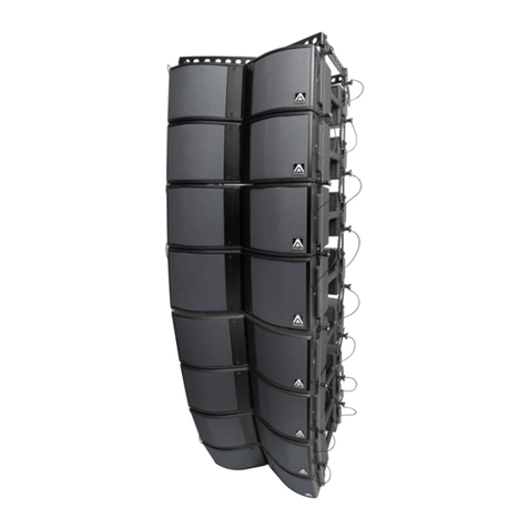
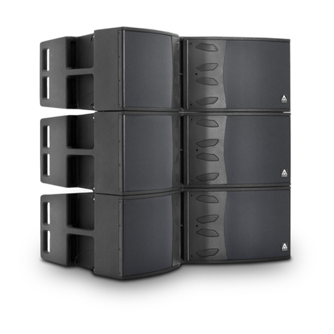
A line array is a group of independent sound sources, which are vertically stacked in
order to transform the spherical wave fronts generated by individual sources into a
single flat wave front.
Fig.1. Wave field interference for different wave fronts.
To carry out effectively arraying individual sound sources the system must follow the
acoustic coupling conditions based on the wavelength, the shape of each source, the
surface area of each transducer and the relative source separation.
An assembly of individual sound sources arrayed with regular separation between the
sources on a plane or curved continuous surface is equivalent to a single sound source
having the same dimensions as the total assembly if the following conditions are
fulfilled:
•The step of source separation, defined as the distance between the acoustic
centres of the individual sources, is smaller than half the wavelength over the
bandwidth of operation.
d<= λ/2
