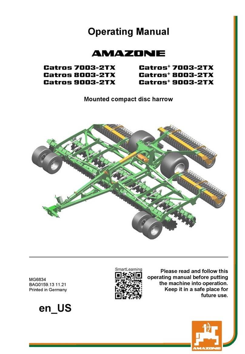
AMAZONEN-Werke AMAZONE Catros 7003XL-2TX User manual

Operating Manual
az
Catros 7003XL-2TX
Catros 8003 XL -2TX
Mounted compact disc harrow
MG7105
BAG0210.8
10.22
Printed in Germany
Please read and follow this
operating manual before pu
t
ting
the machine into opera
tion.
Keep it in a safe place for
future use.
en

2
Catros BAG0210.8
10.22
Reading the instruction
Manual and following it should seem to be in-
convenient and superfluous as it is not
enough to hear from others and to realize that a
machine is good, to buy it and to believe that now
everything should work by itself. The person in
question would not only harm himself but also
make the mistake of blaming the machine for pos-
sible failures instead of himself. In order to ensure
success one should enter the mind of a thing,
make himself familiar with every part of the ma-
chine and get acquainted with how it's handled.
Only in this way could you be satisfied both with
the machine and with yourself. This goal is the
purpose of this instruction manual.
Leipzig-Plagwitz 1872.

Identification data
Catros
BAG0210.8 10.22
3
Identification data
Enter the machine identification data here. You will find the identifica-
tion data on the rating plate.
Machine identification number:
(ten-digit)
Type: Catros
Year of manufacture:
Basic weight (kg):
Approved total weight (kg):
Maximum load (kg):
Manufacturer's address
AMAZONEN-WERKE
H. DREYER SE & Co. KG
Postfach 51
D-49202
Phone:
E-mail:
Hasbergen
+49 5405 501-0
amazone@amazone.de
Spare part orders
Spare parts lists are freely accessible in the spare parts portal at
www.amazone.de.
Please send orders to your AMAZONE dealer.
Formalities of the operating manual
Document number:
MG7105
Compilation date:
10.22
Copyright AMAZONEN-WERKE H. DREYER SE & Co. KG, 2022
All rights reserved.
Reprinting, even of sections, permitted only with the approval of
AMAZONEN-WERKE H. DREYER SE & Co. KG.

Foreword
4
Catros BAG0210.8
10.22
Foreword
Dear Customer,
You have chosen one of the quality products from the wide product
range of AMAZONEN-WERKE, H. DREYER SE & Co. KG. We thank
you for your confidence in our products.
On receiving the machine, check to see if it was damaged during
transport or if parts are missing. Using the delivery note, check that
the machine was delivered in full including the ordered special equip-
ment. Replacement will be made only if a claim is filed immediately!
Please read and follow this operating manual—
in particular, the safety
instructions—before putting the machine into operation. Only after
careful reading will you be able to benefit from the full scope of your
newly purchased machine.
Please ensure that all the machine operators have read this operating
manual before they put the machine into operation.
Should you have any questions or problems, please consult this op-
erating manual or contact your local service partner.
Regular maintenance and timely replacement of worn or damaged
parts increases the lifespan of your machine.
User evaluation
Dear Reader
We update our operating manuals regularly. Your suggestions for
improvement help us to create ever more user-friendly manuals.
AMAZONEN-WERKE
H. DREYER SE & Co. KG
Postfach 51
D-49202
Phone:
E-mail:
Hasbergen
+49 5405 501-0
amazone@amazone.de

Table of Contents
Catros
BAG0210.8 10.22
5
1User information ..........................................................................................8
1.1 Purpose of the document.........................................................................................................8
1.2 Locations in the operating manual...........................................................................................8
1.3 Diagrams used.........................................................................................................................8
2General safety instructions.........................................................................9
2.1 Obligations and liability ............................................................................................................9
2.2 Representation of safety symbols..........................................................................................11
2.3 Organisational measures .......................................................................................................12
2.4 Safety and protection equipment ...........................................................................................12
2.5 Informal safety measures.......................................................................................................12
2.6 User training...........................................................................................................................13
2.7 Safety measures in normal operation ....................................................................................14
2.8 Dangers from residual energy................................................................................................14
2.9 Maintenance and repair work, fault elimination .....................................................................14
2.10 Constructive changes ............................................................................................................14
2.10.1 Spare and wear parts and aids ..............................................................................................15
2.11 Cleaning and disposal............................................................................................................15
2.12 User workstation ....................................................................................................................15
2.13 Warning pictograms and other signs on the machine ...........................................................16
2.13.1 Positioning of warning pictograms and other labels ..............................................................16
2.14 Dangers if the safety information is not observed..................................................................23
2.15 Safety-conscious working ......................................................................................................23
2.16 Safety information for users ...................................................................................................24
2.16.1 General safety and accident prevention information .............................................................24
2.16.2 Hydraulic system....................................................................................................................27
2.16.3 Electrical system ....................................................................................................................28
2.16.4 Attached machines ................................................................................................................28
2.16.5 Brake system .........................................................................................................................29
2.16.6 Tyres ......................................................................................................................................30
2.16.7 Cleaning, maintenance and repairs .......................................................................................30
3Loading and unloading .............................................................................31
4Product description ...................................................................................32
4.1 Overview of subassemblies ...................................................................................................32
4.2 Safety and protection equipment ...........................................................................................33
4.3 Supply lines Safety and protection equipment.......................................................................33
4.4 Transportation equipment ......................................................................................................34
4.5 Intended use ..........................................................................................................................35
4.6 Danger area and danger points .............................................................................................36
4.7 Rating plate ............................................................................................................................37
4.8 Technical data........................................................................................................................38
4.8.1 Weights and tyre load capacity ..............................................................................................39
4.9 Necessary tractor equipment .................................................................................................40
4.10 Noise production data ............................................................................................................40
5Structure and function ..............................................................................41
5.1 Function .................................................................................................................................41
5.2 Hydraulic system connections ...............................................................................................42
5.2.1 Coupling the hydraulic hose lines ..........................................................................................43
5.2.2 Uncoupling the hydraulic hose lines ......................................................................................44
5.3 Dual-circuit service brake system ..........................................................................................45
5.3.1 Coupling the brake and supply lines ......................................................................................46
5.3.2 Uncoupling the brake and supply lines ..................................................................................47

Table of Contents
6
Catros BAG0210.8
10.22
5.4 Hydraulic service brake system ............................................................................................ 48
5.4.1 Coupling the hydraulic service brake system........................................................................ 48
5.4.2 Uncoupling the hydraulic service brake system .................................................................... 48
5.4.3 Emergency brake .................................................................................................................. 49
5.5 Parking brake ........................................................................................................................ 50
5.6 Two-row disc cultivator.......................................................................................................... 51
5.7 Side disc................................................................................................................................ 53
5.8 Deflector guides .................................................................................................................... 53
5.9 Crushboard (optional............................................................................................................. 54
5.10 Cutting roller .......................................................................................................................... 55
5.11 Wedge ring tyre roller ............................................................................................................ 56
5.12 Rear harrow (optional)........................................................................................................... 58
5.13 Running gear and drawbar.................................................................................................... 59
5.14 ContourFrame (CF) - Folding sections with compressive preloading................................... 60
5.15 No ContourFrame (CF) - Folding sections without pre-load pressure .................................. 60
5.16 Jack ....................................................................................................................................... 61
5.17 Moveable jack ....................................................................................................................... 61
5.18 Support wheels...................................................................................................................... 62
5.19 Safety chain between tractor and implements ...................................................................... 63
5.20 Safety device against unauthorised use ............................................................................... 63
5.21 Hectare counter (optional)..................................................................................................... 64
5.22 Central lubrication (optional) ................................................................................................. 65
5.23 GreenDrill catch crop sowing unit ......................................................................................... 66
5.24 Liquid manure equipment...................................................................................................... 66
6Commissioning ......................................................................................... 67
6.1 Checking the suitability of the tractor .................................................................................... 68
6.1.1 Calculating the actual values for the total tractor weight, tractor axle loads and load
capacities, as well as the minimum ballast ........................................................................... 68
6.1.2 Requirements for tractor operation with attached machines................................................. 72
6.2 Securing the tractor / machine against unintentional start-up and rolling ............................. 76
7Coupling and uncoupling the machine ................................................... 77
7.1 Coupling the machine............................................................................................................ 77
7.2 Uncoupling the machine........................................................................................................ 80
8Adjustments............................................................................................... 82
8.1 Aligning the implement horizontally....................................................................................... 82
8.2 Working depth of the discs.................................................................................................... 84
8.2.1 Manual working depth adjustment ........................................................................................ 84
8.3 Intensity of the crushboard.................................................................................................... 85
8.4 Adjusting the preload pressure of the cutting roller............................................................... 86
8.5 Working depth of the border elements .................................................................................. 86
8.6 Adjusting the scraper of the rollers........................................................................................ 87
8.7 Height of towing eye.............................................................................................................. 87
9Transportation ........................................................................................... 88
10 Use of the machine ................................................................................... 90
10.1 Transport and operational position........................................................................................ 91
10.1.1 Changeover from transport position to working position....................................................... 91
10.1.2 Changeover from transport position to working position....................................................... 92
10.1.3 Putting the side elements into transport position/working position ....................................... 94
10.1.4 Moving the edge harrow into transport position / working position ....................................... 94
10.1.5 Lifting and securing the cutting roller .................................................................................... 94
10.1.6 Transport and operating position of the drawbar cylinder..................................................... 95

Table of Contents
Catros
BAG0210.8 10.22
7
10.2 Use on the field ......................................................................................................................96
10.2.1 Using the cutting roller ...........................................................................................................96
10.3 Driving on the headlands .......................................................................................................97
11 Faults ..........................................................................................................98
11.1 Different working depths across the working width? .............................................................98
12 Cleaning, maintenance and repairs..........................................................99
12.1 Cleaning ...............................................................................................................................100
12.2 Lubrication regulations.........................................................................................................101
12.3 Service plan – overview .......................................................................................................103
12.4 Axle (running gear / support wheel) and brake....................................................................106
12.4.1 Inspection instructions for the dual-circuit service brake system.........................................111
12.4.2 Hydraulic brakes ..................................................................................................................112
12.5 Axle bolts..............................................................................................................................112
12.6 Checking the roller ...............................................................................................................112
12.7 Check the coupling device ...................................................................................................113
12.8 Tyres / wheels ......................................................................................................................114
12.8.1 Tyreinflation pressure ..........................................................................................................114
12.8.2 Mounting tyres (workshop work)..........................................................................................115
12.9 Replacing discs (workshop work) ........................................................................................115
12.10 Aligning the disc gangs relative to each other .....................................................................116
12.11 Replacing or turning the cutters of the cutting roller ............................................................116
12.12 Check the central lubrication................................................................................................117
12.13 Hydraulic system..................................................................................................................119
12.13.1 Labelling hydraulic hose lines ..............................................................................................120
12.13.2 Maintenance intervals ..........................................................................................................120
12.13.3 Inspection criteria for hydraulic hose lines...........................................................................120
12.13.4 Installation and removal of hydraulic hose lines ..................................................................121
12.14 Lower link pins check...........................................................................................................122
12.15 Screw tightening torques .....................................................................................................123

User information
8
Catros BAG0210.8
10.22
1 User information
The "User information" section supplies information on using the op-
erating manual.
1.1 Purpose of the document
This operating manual
•Describes the operation and maintenance of the machine.
•Provides important information on safe and efficient handling of
the machine.
•Is a component part of the machine and should always be kept
with the machine or the traction vehicle.
•Keep it in a safe place for future use.
1.2 Locations in the operating manual
All the directions specified in the operating manual are always viewed
in the direction of travel.
1.3 Diagrams used
Instructions for action and reactions
Tasks to be carried out by the user are presented as numbered in-
structions. Always keep to the order of the instructions. The reaction
to instructions is given by an arrow.
Example:
1. Instruction for action 1
→Reaction of the machine to instruction for action 1
2. Instruction for action 2
Lists
Lists without a mandatory sequence a presented as a list with bullet
points.
Example:
•Point 1
•Point 2
Item numbers in diagrams
Numbers in round brackets refer to the item numbers in the diagrams.
The first digit refers to the diagram; the second digit, to the item num-
ber in the illustration.
Example (6)
→Item 6

General safety instructions
Catros
BAG0210.8 10.22
9
2 General safety instructions
This section contains important information on safe operation of the
machine.
2.1 Obligations and liability
Comply with the instructions in the operating manual
Knowledge of the basic safety information and safety regulations is a
basic requirement for safe handling and fault-free machine operation.
Obligations of the operator
The operator is obliged only to let those people work with/on the ma-
chine who
•Are aware of the basic workplace safety information and acci-
dent prevention regulations.
•Have been trained in working with/on the machine.
•Have read and understood this operating manual.
The operator is obliged
•To keep all the warning pictograms on the machine in a legible
state.
•To replace damaged warning pictograms.
If you still have queries, please contact the manufacturer.
Obligations of the user
Before starting work, anyone charged with working with/on the ma-
chine is obliged
•To comply with the basic workplace safety instructions and acci-
dent prevention regulations.
•To read and understand the section "General safety information
"
of this operating manual.
•To read the section "Warning symbols and other labels on the
machine" (page 17) of this operating manual and to follow the
safety instructions represented by the warning symbols when
operating the machine.
•To get to know the machine.
•To read the sections of this operating manual, important for car-
rying out your work.
If the user discovers that a function is not working properly, then they
must eliminate this fault immediately. If this is not the task of the user
or if the user does not possess the appropriate technical knowledge,
then they should report this fault to their superior (operator).

General safety instructions
10
Catros BAG0210.8
10.22
Risks in handling the machine
The machine has been constructed to the state-of-the art and the
recognised rules of safety. However, there may be risks and re-
strictions which occur when operating the machine
•For the health and safety of the user or third persons,
•For the machine,
•For other goods.
Only use the machine
•For the purpose for which it was intended.
•In a perfect state of repair.
Eliminate any faults that could impair safety immediately.
Guarantee and liability
Our "General conditions of sales and business" are always applicable.
These shall be available to the operator, at the latest on the comple-
tion of the contract. Guarantee and liability claims for damage to peo-
ple or goods will be excluded if they can be traced back to one or
more of the following causes:
•Improper use of the machine.
•Improper installation, commissioning, operation and mainte-
nance of the machine.
•Operation of the machine with defective safety equipment or
improperly attached or non-functioning safety equipment.
•Non-compliance with the instructions in the operating manual
regarding commissioning, operation and maintenance.
•Independently-executed construction changes to the machine.
•Insufficient monitoring of machine parts that are subject to wear.
•Improperly executed repairs.
•Catastrophic events as a result of the impact of foreign objects
or force majeure.

General safety instructions
Catros
BAG0210.8 10.22
11
2.2 Representation of safety symbols
Safety instructions are indicated by the triangular safety symbol and
the highlighted signal word. The signal word (DANGER, WARNING,
CAUTION) describes the gravity of the risk and has the following sig-
nificance:
DANGER
Indicates an immediate high risk, which will result in death or
serious physical injury (loss of body parts or long term damage)
if not avoided.
If the instructions are not followed, then this will result in imme-
diate death or serious physical injury.
WARNING
Indicates a medium risk, which could result in death or (serious)
physical injury if not avoided.
If the instructions are not followed, then this may result in death
or serious physical injury.
CAUTION
Indicates a low risk, which could incur minor or medium level
physical injury or damage to property if not avoided.
IMPORTANT
Indicates an obligation to special behaviour or an activity re-
quired for proper machine handling.
Non-compliance with these instructions can cause faults on the
machine or in the environment.
NOTE
Indicates handling tips and particularly useful information.
These instructions will help you to use all the functions of your
machine to the optimum.

General safety instructions
12
Catros BAG0210.8
10.22
2.3 Organisational measures
The operator must provide the necessary personal protective equip-
ment, such as:
•Protective glasses
•Protective shoes
•Protective suit
•Skin protection, etc.
The operation manual
•Must always be kept at the place at which the machine is oper-
ated.
•Must always be easily accessible for the user and maintenance
personnel.
Check all the available safety equipment regularly.
2.4 Safety and protection equipment
Before each commissioning of the machine, all the safety and protec-
tion equipment must be properly attached and fully functional. Check
all the safety and protection equipment regularly.
Faulty safety equipment
Faulty or disassembled safety and protection equipment can lead to
dangerous situations.
2.5 Informal safety measures
As well as all the safety information in this operating manual, comply
with the general, national regul
ations pertaining to accident prevention
and environmental protection.
When driving on public roads and routes, then you should comply with
the statutory road traffic regulations.

General safety instructions
Catros
BAG0210.8 10.22
13
2.6 User training
Only those people who have been trained and instructed may work
with/on the machine. The operator must clearly specify the responsi-
bilities of the people charged with operation, maintenance and repair
work.
People being trained may only work with/on the machine under the
supervision of an experienced person.
People
Activity
Person special-
ly trained for the
activity 1)
Trained person
2)
Person with specialist
training (specialist work-
shop) 3)
Loading/Transport X X X
Commissioning -- X --
Set-up, tool installation -- -- X
Operation -- X --
Maintenance -- -- X
Troubleshooting and fault elimina-
tion
-- X X
Disposal X -- --
Legend:
X..permitted
--..not permitted
1) A person who can assume a specific task and who can carry out
this task for an appropriately qualified company.
2) Instructed persons are those who have been instructed in their
assigned tasks and in the possible risks in the case of improper
behaviour, have been trained if necessary, and have been in-
formed about the necessary protective equipment and
measures.
3) People with specialist technical training shall be considered as a
specialist. Due to their specialist training and their knowledge of
the appropriate regulations, they can evaluate the work with
which they have been charged and detect possible dangers.
Comment:
A qualification equivalent to specialist training can be obtained
through long term activity in the appropriate field of work.
Only a specialist workshop may carry out maintenance and repair
work on the machine, if such work is specifically designated "Work-
shop work". The per
sonnel of a specialist workshop shall possess the
appropriate knowledge and suitable aids (tools, lifting and support
equipment) for carrying out the maintenance and repair work on the
machine in a way which is both appropriate and safe.

General safety instructions
14
Catros BAG0210.8
10.22
2.7 Safety measures in normal operation
Only operate the machine if all the safety and protection equipment is
fully functional.
Check the machine at least once a day for visible damage and check
the function of the safety and protection equipment.
2.8 Dangers from residual energy
Note that there may be residual mechanical, hydraulic, pneumatic and
electrical/electronic energy at the machine.
Use appropriate measures to inform the operating personnel. You can
find detailed information in the relevant sections of this operating
manual.
2.9 Maintenance and repair work, fault elimination
Carry out prescribed setting, maintenance and inspection work in a
timely manner.
Secure all media such as compressed air and the hydraulic system
against unintentional start-up.
Carefully fix and secure larger subassemblies to lifting gear when
carrying out replacement work.
Regularly check that bolted connections are firmly secured and tight-
en if necessary.
When the maintenance work is completed, check the function of the
safety devices.
2.10 Constructive changes
You may make no changes, expansions or modifications to the ma-
chine without the authorisation of AMAZONEN-WERKE. This is also
valid when welding support parts.
Any expansion or modification work shall require the written approval
of AMAZONEN-WERKE. Only use the modification and accessory
parts released by AMAZONEN-WERKE so that the operating permit,
for example, remains valid in accordance with national and interna-
tional regulations.
Vehicles with an official type approval or with equipment conn
ected to
a vehicle with a valid type approval or approval for road transport
according to the German road traffic regulations must be in the state
specified by the approval.
WARNING
Risk of being crushed, cut, caught, drawn in or struck if support-
ing parts break.
It is forbidden to:
•Drill holes in the frame or on the chassis.
•Increasing the size of existing holes on the frame or the chassis.
•Welding support parts.

General safety instructions
Catros
BAG0210.8 10.22
15
2.10.1 Spare and wear parts and aids
Immediately replace any machine parts which are not in a perfect
state.
Use only genuine AMAZONE spare and wear parts or the parts
cleared by AMAZONEN-WERKE so that the operating permit retains
its validity in accordance with national and international regulations. If
you use wear and spare parts from third parties, there is no guarantee
that they have been designed and manufactured in such a way as to
meet the requirements placed on them.
AMAZONEN-WERKE accepts no liability for damage arising from the
use of unapproved spare parts, wear parts or auxiliary materials.
2.11 Cleaning and disposal
Handle and dispose of any materials used carefully, in particular:
•When carrying out work on lubrication systems and equipment
and
•When cleaning using solvents.
2.12 User workstation
The machine must be operated by only one person from the driver's
seat of the tractor.

General safety instructions
16
Catros BAG0210.8
10.22
2.13 Warning pictograms and other signs on the machine
2.13.1 Positioning of warning pictograms and other labels
The following diagrams show the arrangement of the warning picto-
grams on the machine.

General safety instructions
Catros
BAG0210.8 10.22
17
Always keep all the warning pictograms of the machine clean and in a
legible state. Replace illegible warni
ng pictograms. You can obtain the
warning pictograms from your dealer using the order number (e.g.
MD078).
Warning pictograms - structure
Warning pictograms indicate dangers on the machine and warn
against residual dangers. At these points, there are permanent or
unexpected dangers.
A warning pictogram consists of two fields:
Field 1
is a pictogram describing the danger, surrounded by triangular safety
symbol.
Field 2
is a pictogram showing how to avoid the danger.
Warning pictograms - explanation
The column Order number and explanation provides an explanation
of the neighbouring warning pictogram. The description of the warning
pictograms is always the same and specifies, in the following order:
1. A description of the danger.
For example: danger of cutting!
2. The consequence of nonobservance of the danger protection
instructions.
For example: causes serious injuries to fingers or hands.
3. Instructions for avoiding the danger.
For example: only touch machine parts when they have come to
a complete standstill.

General safety instructions
18
Catros BAG0210.8
10.22
Order number and explanation
Warning pictograms
MD078
Risk of contusions for fingers or hands
through accessible moving machine parts!
This danger causes extremely serious injuries
with the loss of body parts such as fingers or
hands.
Never reach into the danger area when the trac-
tor engine is running with PTO shaft / hydraulic
system connected.
MD079
Risk of materials or foreign objects being
flung away by or out of the machine!
These dangers can cause extremely serious and
potentially fatal injuries.
•Keep a sufficient safety distance from the
machine as long as the tractor engine is
running.
•Ensure that all other persons also keep a
sufficient safety distance from the danger
area of the machine as long as the tractor
engine is running.
MD082
Danger of falling from treads and platforms
when riding on the machine!
This danger will cause serious injuries anywhere
on the body or death.
It is forbidden to ride on the machine and/or
climb the running machine. This ban also applies
to machines with treads or platforms.
Ensure that no one rides with the machine.
MD084
Risk of contusions over the whole body from
machine parts moving down from above!
This danger will cause serious injuries anywhere
on the body or death.
•It is forbidden to stand in the swivel area of
moving machine parts.
•Instruct people to leave the swivel area of
moving machine parts before the machine
parts move down.

General safety instructions
Catros
BAG0210.8 10.22
19
MD094
Danger from electric shock or burns due to
unintentional contact with electric transmis-
sion lines or from approaching high-voltage
transmission lines without authorisation.
The danger will cause severe injuries anywhere
on the body or death.
Keep a safe distance to the electric overhead
power lines when swinging machine parts in and
out.
Nominal voltage Safety distance from
transmission lines
up to 1 kV
over 1 up to 110 kV
over 110 up to 220 kV
over 220 up to 380 kV
1 m
2 m
3 m
4 m
MD095
Read and understand the operating manual safe-
ty information before starting up the machine!
MD096
Danger of infection to the whole body from
liquids escaping at a high pressure (hydraulic
fluid)!
This danger will cause serious injuries over the
whole body, if hydraulic fluid escaping at high
pressure passes through the skin and into the
body.
Never attempt to plug leaks in hydraulic lines
using your hand or fingers.
Read and understand the information in the op-
erating manual before carrying out maintenance
and repair work.
If you are injured by hydraulic fluid, contact a
doctor immediately.
MD 101
This symbol indicates jacking points for lifting
gear (jack).

General safety instructions
20
Catros BAG0210.8
10.22
MD102
Danger from unintentional machine starting
and rolling during intervention in the ma-
chine, e.g. installation, adjusting, trouble-
shooting, cleaning, maintaining and repair-
ing.
This danger will cause serious injuries anywhere
on the body or death.
•Secure the tractor and the machine against
unintentional start-up and rolling before any
intervention in the machine.
•Depending on the type of intervention, read
and understand the information in the rele-
vant sections of the operating manual.
MD 114
This pictogram indicates a lubrication point
MD 154
Risk of injury due to non-
compliance with the
approved transport width.
Before folding the implement, install the transport
safety bar.
MD 155
This icon designates the restraint points for tieing
the machine to a transport vehicle allowing the
machine to be transported in a safe manner.
MD174
Danger resulting from the unintentional
movement of the machine!
Causes serious injuries anywhere on the body or
death.
Secure the machine against unintentional
movement before uncoupling the machine from
the tractor. For this, use the p
arking brake and/or
the wheel chock(s).
This manual suits for next models
1
Table of contents
Other AMAZONEN-Werke Farm Equipment manuals