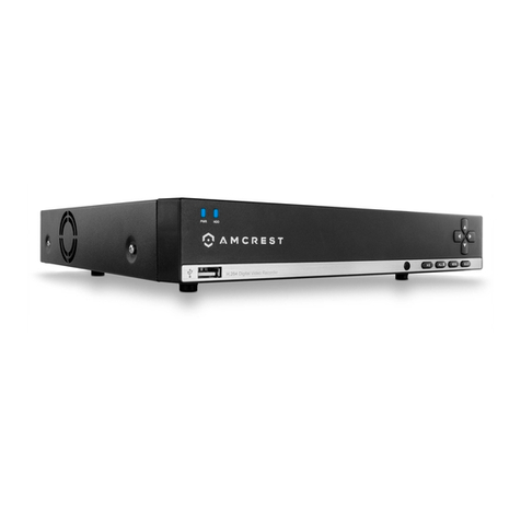
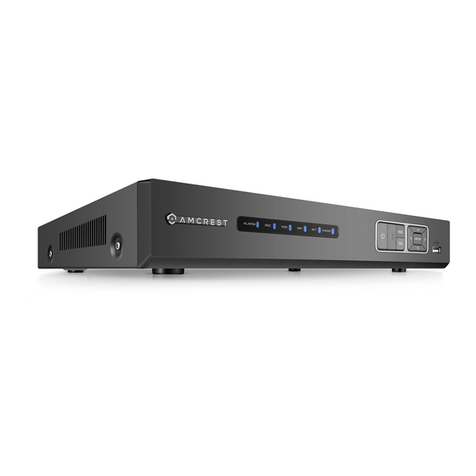
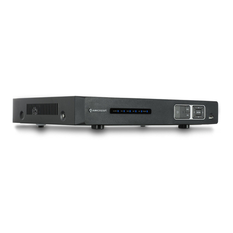
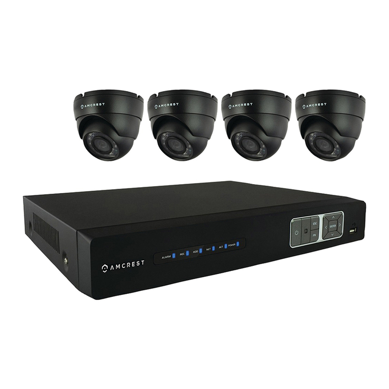
Amcrest A2 User manual

A2 Network Video Recorder
User Manual
Version 1.0.0.
June 15th, 2021

2
Contents
Welcome................................................................................................................................................3
Device Installation..................................................................................................................................7
Web Operation.....................................................................................................................................21
Main Menu ...........................................................................................................................................26
Camera.................................................................................................................................................27
Network................................................................................................................................................32
Storage.................................................................................................................................................43
System .................................................................................................................................................47
Account ................................................................................................................................................50
Live.......................................................................................................................................................51
Search..................................................................................................................................................53
AI..........................................................................................................................................................55
Alarm....................................................................................................................................................64
Maintain................................................................................................................................................74
BackUp.................................................................................................................................................77
Display..................................................................................................................................................77
Audio....................................................................................................................................................80
FAQs/Troubleshooting.........................................................................................................................80

3
Welcome
Thank you for purchasing an Amcrest NVR!
This user manual is designed to be a reference tool for the installation and use of your NVR. The
information provided in this manual may be subject to change without notice. At Amcrest, we want to
ensure the safety of our customers, their loved ones, homes, and businesses each product receives a full
1-year warranty and lifetime support provided directly from Amcrest. Thank you again for being a valued
Amcrest customer.
Important Safeguards and Warnings
All installations and operations of the device should conform to your local electrical safety codes. We
assume no liability or responsibility for any of the fires or electrical shocks caused by improper handling
or installation.
We are not liable for any problems caused by unauthorized modifications or attempted repair. Do not
submerge the device in water or install in areas with high levels of moisture or humidity. Handle with care,
avoid from dropping or placing the device in unsecure areas. The NVR does not have rack mount
compatibility and should be used on flat surfaces.
Overview
Amcrest NVRs use a Linux based operating system to maintain reliable operation. The AI features listed
on the NVR include, “Face Detection, IVS, People Counting, Heat Map, and SMD (Smart Motion Detection).
The features available for use in the NVR will be dependent on the type of camera used on the system as
the AI features are controlled by the camera only. This device allows the user to implement the AI
features from an Amcrest AI camera into the NVR and store the recorded events.
Check Hardware
When you receive the NVR system in the packaging, unpack it, and check all sides of the device to see if
there is any physical damage. The protective materials used for the packaging can protect most accidental
damage during transportation, but to ensure that your equipment is operating as expected, it is
recommended to inspect the product before proceeding further.
On the NVR, check that the label on the NVR is not damaged. The serial number of the unit may be needed
if requesting support and is provides a QR code for a quick means of adding the device to the Amcrest
View Pro app on your mobile device.
Front Panel
Applicable for A2 Series NVRs

4
Icon
Name
Function
NET
Network Abnormality
When a network error occurs or there is no network connection,
this light turns red.
PWR
Power indicator
When the NVR is on, this light remains on.
HDD
HDD abnormal
indicator light
When an HDD error occurs, or the HDD capacity is below the
specified threshold value, this light turns red.
Rear Panel
The rear panel of the NVR may differ model to model.
Non-PoE ports
PoE Ports.
USB 2.0 port
USB 2.0 port. Connect a mouse, USB storage device, etc.
Network port
10M/100Mbps self-adaptive Ethernet port.
HDMI
HDMI Output
High-definition audio and video signal output port.
VGA
VGA video
output port
VGA video output port. Outputs analog video signal. This connects
to the monitor to view analog video.
GND
Ground end
Power Port
DC12V, DC48V Depending on model.

5
MIC IN
Audio input port
Bidirectional talk input port. This is used to receive the analog
audio signal from the device such as a microphone.
MIC Out
Audio output
port
Audio output port. This is used to output the analog audio signal
to devices such as an external RCA speaker.
Bidirectional talk output.
Audio output on 1-window video monitoring.
Audio output on 1-window video playback.
PoE Ports
PoE ports
Built-in switch on certain compatible devices.
For PoE series products, you can use this port to provide power to
a PoE camera.
Connection & Setup
The following instructions will show you how to set up the cables for the NVR, cameras (PoE and Wi-Fi),
as well as a monitor or TV screen.
To set up the cable connections, there are 5 steps:
1. Connect a monitor or TV screen to your NVR. The NVR is compatible with any monitor or screen that
uses a VGA or HDMI connection. For purposes of this guide, we will use a VGA connection. Take a VGA
cable, and connect one end to the VGA port on your monitor/screen and the other end to the VGA port
on the back panel of your NVR.
2. Connect an Ethernet cable to your router then connect the other end of the cable to the Ethernet
port on the back of the NVR.
3.Connect the cameras to power.
For PoE NVRs/cameras: connect an Ethernet cable to the Ethernet port attached to the camera then
connect the other end of the Ethernet cable to a PoE port on the NVR.
Note: PoE cameras can either be powered with a PoE connection or with a standard power adapter (sold
separately). If the NVR does not have PoE ports, connect the PoE camera to a PoE compatible router or
switch that is on the same network as the NVR.
For non-PoE NVRs/cameras: Connect the power adapter to the power port attached to the camera.
Then, plug the adapter into a wall outlet or power strip.
4. Connect the NVR’s power adapter into the power port on the back of the NVR.
Note: If your NVR has a 3-prong power cord, connect the input of the cord into the power input of the
NVR.
5. Finally, connect the other end of the power cable into a wall outlet or power strip to turn on the NVR.
Some models may feature a power switch on the back which may need to be turned on to power the
device.

6
Hard Drive Installation
Hard drives are typically sold separately, when installing a hard drive to the device, please make sure to
use a hard drive with 7200rpm or higher. Please follow the instructions below to install a hard disk drive
(HDD).
All the figures listed below are for reference only. Slight differences may be found on the front or rear
panel.
The NVR has connections for only 1 hard drive inside the case and the hard drive must be no bigger than
10TB (Terabytes).
To install your hard drive, the following is needed:
A medium sized (regular) Phillips-head screwdriver - not included
A hard drive - not included (unless you purchased a ‘kit’ that does have one included)
Four hard drive fastening screws - included
Note: Before installing the hard drive, make sure the NVR is powered off and completely disconnected
from power.
1. Loosen the screws on
the upper cover and side
panel.
2. Attach four screws in the HDD
(Turn three times.)
3. Place the HDD in accordance
with the four holes on the bottom.
4. Turn the device over
secure the screws.
5. Connect the HDD data cable
and power cable to the HDD.
6. Attach the cover onto the NVR
and secure it using the screws.
Once the hard drive is installed, turn on the NVR. If the hard drive for your NVR was not setup properly
you may hear a beeping noise. This indicates the NVR does not have the proper connection with your hard
drive.

7
Factory Reset Procedures
A factory reset will revert the device back to its original factory settings. To begin the process, you will
need to remove the NVR cover. Use a Phillips head screwdriver to remove the screws on the back/sides
of the NVR. Once the screws have been removed, lift the lid to expose the NVR's motherboard. Please
make sure the NVR is powered on as well to complete the process.
On the motherboard you will notice a small black button. This is the factory reset switch for your NVR:
To factory reset the NVR, press, and hold the factory reset switch for 4 –5 seconds and unplug the power
adapter. Once power is removed from the unit, press, and hold the factory reset switch for an additional
4 - 5 seconds and power plug the adapter back into the unit. Continue pressing the factory reset button
until you hear a beep and release. The device will be reset to its original factory settings.
Device Installation
After applying power to the NVR, the system will turn on. Allow the NVR to finish loading. The Device
Initialization screen will appear. Select your location, language, and video standard then click Next to
continue.
Select your time zone as well as current date and time. Click Next to continue.

8
Enter Password
Create a new admin password for your NVR. The password for your device should be between 8 and 32
characters. A combination of letters, numbers, and symbols are recommended when setting up your
password.
Note: Please do not use special symbols like ‘ ‘ ; : &
Once you have entered a new password for your device, confirm the password in the next field. A hint for
the password is optional but is recommended in case you forget the password. You can also disable or
enable the unlock pattern toggle switch as this feature is optional. Click Next.
Unlock Pattern
This is an optional security measure for your device. To set an unlock pattern, use your mouse to draw a
design that you will remember. Draw the pattern again to confirm. If you do not want to assign an unlock
pattern, you can click ‘Skip’to skip this process.

9
If you have assigned an unlock pattern, you will need to draw the pattern again to confirm your assigned
unlock pattern.
Password Protection
Additional means of password protection and retrieval can be set up in this menu. If you would like to
reset your password using your email, make sure the email address checkbox is enabled and enter a valid
email address in the Email Address field. The email address will be retained in the system.
If you do not want to use an email address you can disable the email address option. As a secondary
means of recovering your password, you can apply security questions to your NVR. To add a question,
select a question from the drop-down menus for Question 1, Question 2, and Question 3 and enter the
answers to those questions in the Answer fields.

10
Once this section is complete, click on the Next button to Save your information to the device.
Startup Wizard Walkthrough
The first page of the Startup Wizard will appear which allows you to setup any network, P2P, camera, and
hard drive (HDD) settings.
Network
Unless you have a specific reason to change these settings, it is best to leave them as they are. Please
note, the IP address for the NVR will be the address used to access your NVR’s web user interface on a
laptop or PC. It is highly recommended to make sure the IP is set as static. To set the NVR to a static IP
address, click on “Modify” and disable the DHCP toggle switch. Click Save. This will set the network mode
to Static.
Click the Test to test the overall health and status of your network connection once complete, click the
Back button to return to the previous menu. Click Next.
P2P
The next screen that appears is the P2P screen. This screen allows you to connect your NVR to your mobile
device using the Amcrest View Pro App. Ensure the P2P toggle switch is enabled and the P2P status reads

11
“Online”. To download the app, use your mobile device’s camera and scan the Cell Phone Client QR code.
When using the app, use the SN QR Code for quick access to the serial number for your NVR. Click Next.
Camera Registration
The next screen that appears is the Camera Registration screen. This is where you can begin adding
cameras to the NVR. If the cameras are not directly connected to the back of the NVR, please make sure
they are active and on the same network as the NVR before proceeding.
To begin adding a device, click on Search Device to allow the NVR to scan for connected devices on your
network. A list of applicable connected devices will show on the screen. Select your devices by clicking on
the checkbox next to the device and click Add to add the device into the Added Devices menu.
If the status of your camera is red, it indicates the camera is not properly registered to the NVR. This could
be because the password for the camera is not entered properly in the system. To modify the password
for your camera, click on the edit icon (pencil) located in the Edit column in the Added Device menu.
Select the Password field and use the onscreen keyboard to enter the password for your camera. Once
the password has been entered, click Connect then click Save to continue.
Note: If this is a new device and a password has not been added the password will be admin.
Once the password has been properly set the Status indicator will turn green indicating the camera has
been properly added. Once the camera(s) have been successfully added, Click Next.
HDD Manager
The next screen will be the hard drive manager screen. This screen allows the user to verify the hard drive
is being read by the device as well as provides an option to format. Please note, it is highly recommended
to format the hard drive before proceeding.
To format the hard drive, select the hard drive you would like to format from the list and click Format.
Toggle the Clear HDD Database toggle switch on and click Save. Enter the password for the NVR and click
Save. Once the hard drive has been successfully formatted click Save.
Audio Ports
Device Connection
Connect an RCA microphone to the “Audio In” port on the back of the device. If using an audio out device,
such as an RCA speaker, plug the speaker into the “Audio Out” port on the back of the device.
Most audio codecs will use ACC as a default audio codec. To adjust audio settings, log into your NVR and
access the Encode menu for the specific device and click on “More Setting” (Camera > Encode > More
Setting). Verify the codec and settings are correct and click Save to Save the audio settings.

12
Mouse Operation
Please refer to the following sheet for mouse operation instructions.
Left click
When you have selected one menu item, left mouse click to view the menu
content.
Modify a checkbox or motion detection status.
Click a combo box to show the dropdown list
In an input box, you can select different input methods. Left click the
corresponding button on the panel to input a numeral/English character.
(small/capitalized). Here ← stands for backspace. _stands for space.
In English input mode: _ stands for inputting a space icon and ← stands for
deleting the previous character.
In numeral input mode: _ stands for clear and ← stands for deleting the previous
numeral.
Double left
Implement special control operations such as double click one item in the file list
to playback the video.
Mouse
click
In multiple-window mode, double left click one channel to view in full-screen.
Double left click the current video again to go back to previous multiple-window
mode.
Right click
In real-time monitor mode, this pops up a shortcut menu.
Exit the current menu without saving any modifications.
In a numeral input box: Increase or decrease the numeral value.

13
Scroll middle
button
Switch the items in the check box.
Page up or page down
Move mouse
Select current control or move control
Drag mouse
Select the motion detection zone
Select the privacy mask zone
Video Wall
Please note the displayed window amount may vary depending on how many channels your NVR can
support. The following figure is for reference only.
Please note, the video wall menu will also provide a separate portion that will display the current bit
rate of each channel. The bitrate for each device is measured in Kb/S.
1
Recording status
3
Direct PoE Connection
2
Motion detection
4
Camera lock

14
Preview Control Interface
Move the mouse to the top center of the video of the current channel, and the system pops up the
preview control interface. If your mouse stays in this area for more than 6 seconds and preforms no
operation, the control bar automatically hides.
Instant Playback
Click this button to instantly playback any previous motion detection events that were captured by the
camera. Please note, a hard drive must be installed in the device to playback any recorded events or
snapshots.
Digital Zoom
This option allows you to digitally zoom in on a specific area on the live view interface. To use digital
zoom, click the digital zoom button and click an area on the live view screen. Drag the mouse to select a
zone and release. The live view will zoom in on the set area. To exit digital zoom, right click on the live
view screen to return to its original view.
Manual Record
This option allows you to manually record video. Please note, the NVR can only record videos of a single
channel at a time, if multiple channels are enabled, no footage will be retained. To manually record
video, insert a USB flash drive into a USB port on the NVR and click on the manual record button. Click
on the manual record button again to stop recording. The recording will be Saved to the USB flash drive.
Manual Snapshot
Like the manual record button, this option allows you to manually snapshots. To manually take a
snapshot, insert a USB flash drive into a USB port on the NVR and click on the manual snapshot button.
The snapshot will be Saved to the USB flash drive.
Audio talk
This option allows for bidirectional talk. Please note, an external microphone and speaker will need to be
applied to the audio in and audio out ports on the back of the NVR for this to function. To activate, click
on the audio talk button and use an external RCA microphone and speaker to talk. To disable this function,
click on the audio talk button again.
Switch Stream
This option allows the device to switch between main stream and sub stream feeds. Please note, switching
to a sub stream feed will provide less quality than a main stream feed.
Adding Additional Devices
To add multiple devices from the video wall interface. Hover the mouse over the channel you would like
to select and click the (+) icon.

15
This will take you to a camera registration screen. Click on Device Search or Manual Add to begin adding
the device. If using Device Search, please make sure the camera is on the same network as the NVR before
searching. Once the camera has been detected, click on the device to highlight it, and click Add.
Please note, if the device is not registering to the device, the username or password may need to be
updated for the camera. This can be resolved by right clicking on the screen and choosing Camera
Registration.
In the registration screen, click on the Edit icon (pencil) and ensure the username and password are
correct and click Connect. Once this is verified click Save. The status indicator for the camera should turn
green, indicating the camera has been added successfully.

16
Note: For maximum compatibility when accessing your camera in a web browser or third-party
applications, our H.265 compatible products will be factory defaulted to H.264 but for increased
performance, the camera's settings can be upgraded to H.265 compression. H.265 provides a more
advanced technology than H.264 and allows the device to reduce file size which ultimately helps to reduce
required bandwidth without sacrificing frames per second or resolution. To activate H.265 compression,
click on the H.265 Auto Switch to switch the camera to H.265 compression.
For more information on H.265 compression, please visit: amcrest.com/support
To exit the registration menu, right click on the video wall to display the connected devices. The process
can be repeated to add additional cameras if needed. To add the device manually, click Manual Add and
enter the information for your camera into the interface. Click Save to activate the camera.

17
Shortcut Menu
To access the shortcut menu for the device, right click on the video wall screen to access the shortcut
options menu.
Main Menu: Click this option to exit the video wall and access the main menu options the NVR.
Search: Click this option to access the playback interface.
PTZ: Click this option to access the pan/tilt/zoom interface. Please note, this option is only applicable if a
PTZ device is connected to the NVR. PTZ allows you to control the PTZ direction, speed, zoom, focus, iris,
preset, tour, scan, pattern, aux function, light and wiper, rotation, etc.
Full Screen: Click the full screen option to display a selected feed in full screen.
Speed: Controls the PTZ movement speed. Its values can range from 1, being the slowest, and 8 being the
fastest.
Zoom: Use the “+” and “-“icons to zoom in or zoom out on the interface.
Focus: Use the “+” and “-“icons to focus the image.
Iris: Use the “+” and “-“ icons to control the iris behavior of the camera.
PTZ Trace: Provides the ability to store a sequence of camera movements as a preset.
In the middle of the eight direction arrows, there is a 3D intelligent positioning key. Please make sure
your protocol supports this function and you need to use the mouse to control it. Click this key and the
system goes back to the single screen mode. Drag the mouse in the screen to adjust the section size. The
dragged zone supports 4X to 16X speeds. The smaller zone you dragged, the higher the speed.

18
Name
Function key
Function
Function key
Function
Zoom
-
Out
+
In
Focus
-
Near
+
Far
Iris
-
Close
+
Open
Click the “>” icon to open the menu. You can set preset, tour, pattern, scan, etc.
Refer to the following sheet for detailed information.
Please note the above interface may vary due to different protocols. The button is grey and cannot be
selected if the current function is null.
Right click or click the ESC button on the front panel to go back
Icon
Function
Icon
Function
Preset
Auto Pan
Tour
Flip
Pattern
Reset
Auto Scan
PTZ Settings
Call PTZ Function
Preset
Input the Preset value and then click to call a preset. Click again to stop the call.
Call Tour
Input the Tour value and then click to call a tour. Click again to the stop call.
Call Pattern
Input the Pattern value and then click to call a pattern. Click again to stop the call.

19
Call Scan
Input the Scan value and then click to call a scan. Click again to stop the call.
Auto Pan
Click to enable the camera to enable any auto pan presets set in the device. Click again to
disable this preset.
Flip
Click to enable the camera to flip its image.
Reset
Click to return to exit the current PTZ operation.
PTZ Function Setup
Click to go to the following interface to set preset, tour, pattern, and scan.
Preset Setup
Click the Preset button and use the eight direction arrows to adjust camera to the proper position.
Click the box next to Preset and then input the preset number. Click the Set button to Save the current
preset.
Tour Setup
Click the Tour tab. Input tour value and preset No. Click the Add preset button to add the current preset
to the tour.
Tips
Repeat the above steps to add more presets to the tour. Click the Del preset button to remove it from the
tour. Please note some protocols do not support the delete preset function.

20
Pattern Setup
Click the Pattern button and input pattern number.
Click the Begin button to start the direction operation. Or you can go back to the screen below to operate
zoom/focus/iris/direction operation.
Click the End button.
Scan Setup
Click the Scan button.
Use the direction buttons to set the camera’s left limit and then click the Left button. Use the direction
buttons to set the camera’s right limit and then click the Right button. Now the scan setup process is
complete.
View 1: View a single device in the video wall.
View 4: View 4 simultaneous devices in the video wall. The same concept will apply to any other View
(Window Split) options in this menu.
Sequence: Allows the user to display in which sequence the cameras will be displayed in the video wall.
Custom Split: Allows the user to customize how the splits will be arranged on the video wall.
Table of contents
Other Amcrest DVR manuals

Amcrest
Amcrest NV42 EI Series User manual

Amcrest
Amcrest 960H User manual

Amcrest
Amcrest XVR/H5 User manual

Amcrest
Amcrest NVR11H Series User manual

Amcrest
Amcrest AMDV5M32-6TB User manual

Amcrest
Amcrest 960H User manual

Amcrest
Amcrest AMDV7204-2B2D User manual

Amcrest
Amcrest H5 Series User manual

Amcrest
Amcrest AMDV10808-8B User manual

Amcrest
Amcrest General 720P(V2) Mini 1U Series User manual
Popular DVR manuals by other brands

ApexCCTV
ApexCCTV AP-16CO Configuration guide

Privacy Electronics
Privacy Electronics DS-DVR04 Series user manual

urmet domus
urmet domus 1093/004H User manual/instructions

ArcVision
ArcVision ARC19817 user manual

TECHVIEW
TECHVIEW QV-3147 user manual

Security Camera King
Security Camera King PENDVR-EL8M4K manual