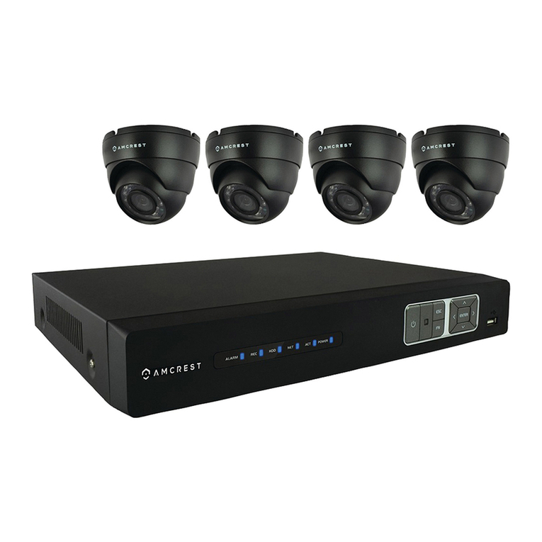
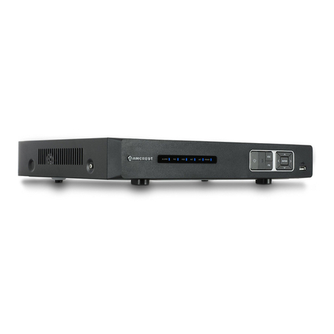
Amcrest AMDV4M4 User manual

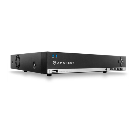
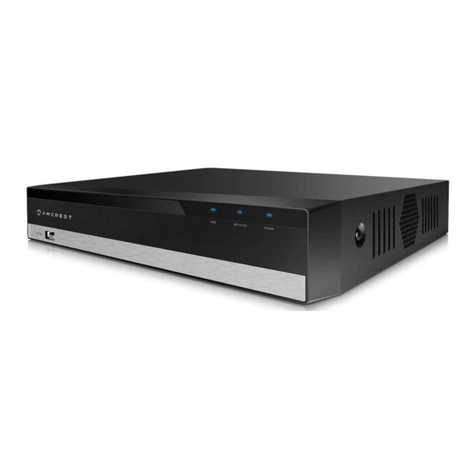
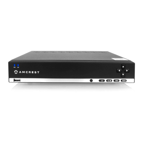
Amcrest AMDV4M4
4MP UltraHD 4CH HDCVI DVR
User Manual

2
Version 2.0.10
Revised April 12th, 2018
Contents
Welcome................................................................................................................................................................................ 4
Important Security Warning .............................................................................................................................................. 4
Important Safeguards and Warnings................................................................................................................................. 5
1. Features and Specification............................................................................................................................................. 5
1.1 Overview.................................................................................................................................................................. 5
1.2 Features ................................................................................................................................................................... 6
2. Overview and Controls .................................................................................................................................................. 7
2.1 Front Panel............................................................................................................................................................... 7
2.2 Rear Panel ................................................................................................................................................................ 8
2.3 Device Connection Example..................................................................................................................................... 9
2.4 Remote Control...................................................................................................................................................... 10
2.5 Mouse Control ....................................................................................................................................................... 12
3. Connection and Installation......................................................................................................................................... 14
3.1 Check Hardware..................................................................................................................................................... 14
3.2 Hard Drive Installation ........................................................................................................................................... 14
3.3 Connection Port Information................................................................................................................................. 15
3.4 DVR Assembly Guide.............................................................................................................................................. 20
4. Overview of Navigation and Controls.......................................................................................................................... 24
4.1 Startup and Shut down .......................................................................................................................................... 24
4.2 Startup Wizard ....................................................................................................................................................... 25
4.3 Live View ................................................................................................................................................................ 29
4.4 Right-Click Menu.................................................................................................................................................... 31
4.5 Navigation Bar........................................................................................................................................................ 38
4.6 USB Device Auto Popup ......................................................................................................................................... 40
4.7 Main Menu............................................................................................................................................................. 41
4.8 Main Menu: Operation .......................................................................................................................................... 42
4.9 Main Menu: Information ....................................................................................................................................... 51
4.10 Main Menu: Settings............................................................................................................................................ 58
5 Web Operation ........................................................................................................................................................... 115
5.1 Local Web Access................................................................................................................................................. 115
5.2 Remote Web Access ............................................................................................................................................ 116
5.3 Web Access Interface........................................................................................................................................... 119

3
5.4 Web Access Settings Menu.................................................................................................................................. 125
5.5 Web Access Information Menu ........................................................................................................................... 127
5.6 Log Out................................................................................................................................................................. 129
6. FAQs/Troubleshooting............................................................................................................................................... 129
Appendix A: Compatible Backup Device List.................................................................................................................. 133
Appendix B: Compatible CD/DVD Device List ................................................................................................................ 139
Appendix C: Compatible Display List.............................................................................................................................. 139
Appendix D: Compatible Switch List .............................................................................................................................. 140
Appendix E: Compatible Wireless Mouse List................................................................................................................ 141
Appendix F: Toxic or Hazardous Materials or Elements ................................................................................................ 141

4
Welcome
Thank you for purchasing our Amcrest HDCVI DVR!
This user manual is designed to be a reference tool for the installation and operation of your HDCVI DVR system.
Here you can find information about the DVR’s features and functions, as well as information to aid in troubleshooting.
Many of the setup and installation sections below have corresponding videos on YouTube
To access the setup videos, please go to http://amcrest.com/videos
NOTE: This user manual is applicable to all 4, 8 and 16 channel Amcerst HDCVI DVRs, including any S2, S3, and S4
models.
Important Security Warning
To keep your Amcrest camera secure and prevent unauthorized access, please make sure to follow the steps below:
•Always make sure that your camera has the latest firmware as listed on
www.amcrest.com/firmware
•Never use the default password for your camera. Always ensure that your password
is at least 8-10 characters long and contains a combination of lowercase characters,
uppercase characters as well as numbers.
For access to the quick start guide and other support information, go to http://amcrest.com/support
To contact Amcrest support, please do one of the following:
•Visit http://amcrest.com/contacts and use the email form
•Call Amcrest Support using one of the following numbers Toll Free: (888) 212-7538
International Callers (Outside of US): +1-713-893-8956
USA: 888-212-7538
Canada: 437-888-0177
UK: 203-769-2757
•Email Amcrest Customer Support support@amcrest.com

5
Important Safeguards and Warnings
1.Electrical Safety
All installation and operation should conform to your local electrical safety codes.
The product must be grounded to reduce the risk of electric shock.
We assume no liability or responsibility for any fires or electrical shock caused by improper handling or installation.
2.Transportation Security
Heavy stress, violent vibrations, and excess moisture should not occur during transportation, storage, and installation of
the device.
3.Installation
Handle the device with care. Keep the device right side up.
Do not apply power to the DVR before completing installation.
Do not place objects on top of the DVR.
4.Repair Professionals
All the examination and repair work should be done by qualified service engineers.
We are not liable for any problems caused by unauthorized modifications or user-attempted repair.
5.Environment
The DVR should be installed and kept in a cool, dry place away from direct sunlight, flammable materials, explosive
substances, etc.
This product should be transported, stored, and used only in the specified environments as stated above.
6. Accessories
Be sure to use only the accessories recommended by manufacturer.
Before installation, please open the package and check to ensure that all the components are present.
Contact the retailer that you purchased from, or Amcrest directly if anything is broken or missing in the package.
NOTE: This user manual is applicable to all 4, 8 and 16 channel Amcerst HDCVI DVRs, including any S2, S3, and S4
models.
1. Features and Specification
1.1 Overview
The Amcrest HDCVI is an excellent digital surveillance product designed for the security field. The DVR uses a Linux
based OS to maintain reliable operation. It’s easy to use and can be set up in a relatively small amount of time. It has
various functions such as recording, playback, and monitoring functionality and it synchronizes audio and video by
default.
This HDCVI DVR adopts a high-quality design to achieve high levels of reliability and security. It can be configured to
work locally, as well as on a network. With the provided professional surveillance software (PSS) tool, as well as many
built-in tools on the DVR’s OS, this device can also help monitor and track network usage by the device itself.

6
By using industry standard cables and the latest technology, the DVR can be used with a variety of different cameras
(Analog, HDCVI, or IP, etc) and can work with most standard security system cable setups. This product can be used in a
variety of locations such as banks, residential neighborhoods or homes, factories, warehouses, transportation
(trucking), and more.
1.2 Features
The Amcrest HDCVI has the following features:
•Real-time Monitoring
The HDCVI has an analog output port, VGA port, and an HDMI port. You can use a variety of monitors to
display the DVR’s interface, and the DVR can support VGA and HDMI output at the same time.
•Storage Functionality
The DVR can record multiple video and audio streams to the built-in hard drive to allow for playback of any
recorded media.
•Compression Format
By utilizing advanced compression, the DVR can support multiple channels of audio and video, decoding audio
and video from each channel to maintain video and audio synchronization.
•Backup Function
The DVR supports backup of recorded media and settings via the USB port. A variety of devices can be used for
backup purposes, such as a flash drive, portable HDD, or even a CD/DVD burner.
•Advanced Playback Function
This device supports independent real-time recording for each channel and can support search, fast forwarded
playback, recorded searches, and downloading of videos and screenshots. The DVR can also playback in slow
motion, backwards, and frame by frame as needed. When recording, the DVR shows a date/time overlay to
ensure accurate viewing of events when they occurred. Lastly, the DVR can support video enlargement of
certain zones within a stream.
•Network Operation
The DVR has built-in tools to allow for remote network real-time monitoring, remote recording of searches,
and remote PTZ control.
•Alarm Activation Function
On the back of the DVR there are ports for installation and connection of alarm outputs to enable alarm or
light activation based on activity within the video stream. The alarm input and output circuits are protected to
ensure device safety.
•Communication Port
By including an RS485 port, the device can support PTZ decoding, as well as various other decoding protocols
to allow PTZ control of the attached cameras.
•Intelligent Operation
The DVR supports a variety of mouse and keyboard devices to enable easy use of the device. There is also a
feature that allows for the saving of settings on the device.

7
•Advanced Network Protocol Support
The DVR is UPnP compatible, and includes functionality for use with PPPoE, and DDNS protocols to allow
remote and local connection with a large variety of network hardware.
Note: There may be slight differences in functionality due to the existence of different product series.
2. Overview and Controls
This section provides information about the physical design and controls for the HDCVI DVR. Please refer to the
diagrams below to become acquainted with the DVR and its physical features.
2.1 Front Panel
2.1.1 4-Channel Front Panel

8
2.2 Rear Panel
2.2.2 General 720p/1080p 4-Channel System
Note: This is for example purposes only, the diagram represents a 4 Channel system however, is applicable to all units
provided in the description.
The 4-channel system rear panel is as shown below.
Please refer to the following table for detailed information:
SN
Icon
Name
Note
1
A
RS485(RS-485)
communication port
RS485_A port. It is the cable A. You can
connect to the control devices such as
speed dome PTZ.
RS485_B. It is the cable B. You can
connect to the control devices such as
speed dome PTZ.
B
2
Power Input port
Input 12V DC.
3
Network port
100M Ethernet port
4
VGA
VGA video output port
VGA video output port. Output analog
video signal. Can connect to the monitor
to view analog video output.
5
VIDEO IN
Video input port
Connect to analog camera, video input
signal.
6
Audio
OUT
Audio output port
Connect to video output device such as
sound box.
7
Audio IN
Audio input port
Connect to audio input device such as
microphone.

9
8
HDMI
High definition media
interface
High definition audio and video signal
output port. It transmits uncompressed
high definition video and multiple-channel
data to the HDMI port of the display
device.
9
USB 2.0 port
Connect to USB storage device, mouse,
burning DVD-ROM etc.
10
GND
Ground end.
2.3 Device Connection Example
The below diagram provides an example of the variety of devices the DVR can interface and connect with.

10
2.4 Remote Control
The diagram below shows the remote control that comes with the Amcrest HDCVI System.
Serial Number
Name
Function
1
Power button
Click it to boot up or shut down the device.
2
Address
Click it to input device number, so that you can control
it.
3
Forward
Various forward speeds and normal speed playback.
4
Slow play
Multiple slow play speeds or normal playback.
5
Next record
In playback mode, playback the next video.
6
Previous record
In playback mode, playback the previous video.
7
Play/Pause
In pause mode, click this button to start normal
playback.
In normal playback click this button to pause playback.

11
In real-time monitor mode, click this button to enter
video search menu.
8
Reverse/pause
Reverse playback pause mode, click this button to
start normal playback.
In reverse playback click this button to pause playback.
9
Cancel
Go back to previous menu or cancel current operation
(close upper interface or control)
10
Record
Start or stop record manually
In record interface, work with the direction buttons to
select the record channel.
Click this button for at least 1.5 seconds and the
system will go to the Manual Record interface.
11
Direction keys
Switch current activated control, go left or right. In
playback mode, click up/down button to switch
playback channel. In 1-window playback mode,
click left/right button to control playback speed.
Aux function(such as switch the PTZ menu,
enable/disable reuse button)
12
Confirm /menu key
Go to default button
Go to the menu
13
Multiple-window switch
Switch between multiple-window and one-window.
14
Auxiliary key
In 1-ch monitor mode: pop up assistant function:PTZ
control and Video color.
Switch the PTZ control menu in PTZ control interface.
In motion detection interface, working with direction
keys to complete setup.
In text mode, click it to delete character.
15
0-9 number key
Input password, channel or switch channel.
Shift is the button to switch the input method.

12
2.5 Mouse Control
The following table details the different uses for a computer mouse regarding the DVR’s controls.
Left click
mouse
System pops up password input dialogue box if you have not logged in. In
real-time monitor mode, you can go to the main menu.
When you have selected one menu item, left click mouse to view menu content.
Implement the control operation.
Modify checkbox or motion detection status.
Click combo box to pop up drop down list
In the input box, you can select input methods. Left click the corresponding button on the
panel and you can input numeral/English character (small/capitalized). Here, ← stands for
backspace button. _stands for the space button.
In English input mode: _ stands for input a backspace icon and ← stands for deleting the
previous character.
Double left
click mouse
Implement special control operation such as double click one item in the file list to
playback the video.
In multiple-window mode, double left click one channel to view in full-window.
Double left click current video again to go back to previous multiple-window mode.

13
Right click
mouse
In real-time monitor mode, pops up shortcut menu: one-window, four-window, nine
window and sixteen-window, Pan/Tilt/Zoom, color setting, search, record, alarm input,
alarm output, main menu.
Among which, Pan/Tilt/Zoom and color setting applies for current selected channel. If
you are in multiple-window mode, system automatically switches to the corresponding
channel.
Exit current menu without saving the modification.
Press middle
button
In numeral input box: Increase or decrease numeral value.
Switch the items in the check box.
Page up or page down
Move mouse
Select current control or move control
Drag mouse
Select motion detection zone
Select privacy mask zone.

14
3. Connection and Installation
3.1 Check Hardware
When you receive the DVR system in the packaging, unpack it, and check all sides of the DVR to see if there is any
physical damage. The protective materials used for the packaging of the DVR can protect most accidental damage
during transportation, but to ensure that your equipment is operating as expected, it is recommended to inspect
the product before proceeding further.
On the DVR unit, check specifically that the label on the bottom of the DVR is not damaged. The serial number of
the unit is usually needed to provide support.
Please check that all required items for your DVR are present and accounted for. To check what is included with
your purchase, go to http://amcrest.com/hdcvi-security-camera-systems.html/ and find the product you
purchased, then scroll down and click the “What’s Included” tab. If any item is missing, please contact us as soon
as possible so we can send you the missing component.
3.2 Hard Drive Installation
You can refer to the Appendix for recommended HDD brands and models. Please use a HDD of 7200rpm or higher.
Please follow the instructions below to install a hard disk drive (HDD).
All the figures listed below are for reference only. Slight differences may be found on the front or rear panel.
1. Loosen the screws of the
upper cover and side panel.
2. Attach four screws in the HDD
(Turn three times).
3. Place the HDD in accordance with
the four holes on the bottom.

15
4. Turn the device upside down
and then turn the screws in
firmly in the chassis.
5. Attach the HDD firmly.
6. Connect the HDD cable and
power cable.
7. Put the cover on in accordance
with the clip and then place the
upper cover back on.
8. Secure the screws in the rear
panel and the side panel.
Note:
•An HDD is included with the DVR by default.
•To connect the HDD, connect the HDD data cable and the power cable before attaching the HDD in the device.
•To remove the front cover, push the clip first, and then slide the cover off.
3.3 Connection Port Information
3.3.1 Power Supply Connection
Please check to make sure the input voltage is correct, and the power button is in the off position when connecting
the power supply.
We recommend you use an Uninterruptible Power Supply (UPS) to guarantee steady operation of the DVR, as well
as to elongate the life span of the DVR and other peripheral equipment such as attached cameras and other
accessories.
3.3.2 Video Input/Output Connections
3.3.2.1 Video Input Connection Information
The video input interface is BNC.
The input video format includes: PAL/NTSC BNC (1.0VBP- P, B75Ω)
The video signal should comply with your national standards.

16
The input video signal should have high SNR, low distortion; low interference, natural color and suitable
brightness.
To guarantee the stability and reliability of the camera signal, the camera should be installed in a cool, dry place
away from direct sunlight, flammable materials, explosive substances, etc.
The camera and the DVR should have the same grounding to ensure the normal operation of the camera.
Guarantee stability and reliability of the transmission line
Please use high quality, well shielded BNC cable. Please select suitable BNC model according to the transmission
distance.
If the distance is too long, you should use twisted pair cable. You can add video compensation devices or use
optical fiber to ensure video quality.
You should keep the video signal away from the strong electromagnetic interference, especially power lines.
Keep connection lugs closely contacted.
The signal line and shielded wire should be fixed firmly and in well connection. Avoid dry joint, lap welding, and
oxidation.
3.3.2.2 Video Output Connection Information
Video output includes a BNC (PAL/NTSC1.0VP-P,75Ω)output, a VGA output, and a HDMI output. The system
supports BNC, VGA and HDMI output at the same time.
When you are using pc monitor, please pay attention to the following points:
•To defer aging, do not allow the pc monitor to run for a long time.
•Regular demagnetization will keep your device in proper working condition. Keep it away
from strong electromagnetic interference devices.
Using a TV as video output device is not a reliable substitution method. When using a TV as a video output device,
it is advised to turn off the TV from time to time to ensure its longevity. The use of a low-quality TV may result in
the damage of the device.
3.3.3 Audio Input/Output Connections
3.3.3.1 Audio Input Connection Information
The DVR audio input ports uses a BNC type connection.
Due to high impedance of audio input, please use an active sound microphone to get the best audio quality.
Audio transmission is similar to video transmission. Try to avoid interference, look out for dry joints, loose
contacts, and keep the audio devices and cables away from power lines.

17
3.3.3.2 Audio Output Connection Information
The audio output signal parameter is usually over 200mv 1KΩ (BNC or RCA).
It can directly connect to a low impedance earphone, active speaker, or amplifier-drive audio output device.
If the speaker and the microphone cannot be separated spatially, it may create a feedback loop. In this case you
can adopt the following measures:
•Use a better directional microphone.
•Reduce the volume of the speaker.
•Using more sound-absorbing materials in the surrounding area can reduce voice echo and improve the
acoustic environment.
Adjust the layout of the audio output cables to reduce the occurrence of a feedback loop.
3.3.4 Alarm Input/Output Connections
Please read the following before connecting any alarm devices
3.3.4.1 Alarm Input Connection Information
a. Please make sure the alarm input mode is grounded.
b. A grounding signal is needed for alarm input.
c. Alarm input uses a low-level voltage signal.
d. Alarm input mode can be either NO (Normal Open) or NC (Normal Close).
e. When you are connecting two DVRs, or one DVR and one other device, please use a relay to separate them.
3.3.4.2 Alarm Output Connection Information
The alarm output port should not be connected to a high-power load directly (The power load should be less than
1 amp) to avoid high current which may result in relay damage.
3.3.4.3 Connecting a PTZ Decoder
a. Ensure that the decoder has the same grounding with the DVR, otherwise you may not be able to control
the PTZ. Shielded twisted wire is recommended and the shielded layer is used to connect to the ground.
b. Avoid high voltage. Ensure proper wiring and take some thunder protection measures.
c. For signal wires that are too long, 120Ω should be connected in parallel between A, B lines on the far end to
reduce reflection and guarantee the signal quality.
d. “485 A, B” of DVR cannot parallel connect with “485 port” of another device.
e. The voltage between the A,B lines of the decoder should be less than 5v.
3.3.4.4 Alarm Input/Output Details
Important!
Please refer to the specifications for the alarm input and output channel amount. Do not merely count the alarm
input and output channel amount according to the ports on the rear panel.

18
The following interface is based on the 8-channel advanced 1080P (V2) mini 1U Series. Note:
The 32-channel alarm interface diagram is shown below, on page 38.
1,2,3,4,5,6,
7,8,9,10,11,
12,13,14,15,16
ALARM 1 to ALARM 16. The alarms become active in low voltage.
NO1 C1,NO2 C2,
NO3 C3,
Three normal open groups (on/off signal)
Earth cable.
3.3.4.5 Alarm Input Ports
•Grounding alarm inputs. (Normal Open or Normal Close type)
•Please parallel connect COM end and GND end of the alarm detector (Provide external power to the alarm
detector).
•Please parallel connect the Ground of the DVR and the ground of the alarm detector. Please connect
the NC port of the alarm sensor to the DVR alarm input (ALARM) Use the same ground with that of
DVR if you use external power to the alarm device.
3.3.4.6 Alarm Output Ports
•Provide external power to any external alarm device.
•To avoid overloading, please read the following relay parameters sheet carefully.

19
•RS485 A/B cable is for the A/B cable of the PTZ decoder. T+,T-,R+,R- are four-wire double duplex RS485
port.
T+ T-: output wire
R+ R-: input wire
Relay Specification
Model:
JRC-27F
Material
Silver
Rating
(Resistance Load)
Rated switch capacity
30VDC 2A, 125VAC 1A
Maximum switch power
125VA 160W
Maximum switch voltage
250VAC, 220VDC
Maximum switch currency
1A
Insulation
Between contacts with same polarity
1000VAC 1 minute
Between contacts with different
polarity
1000VAC 1 minute
Between contacts and winding
1000VAC 1 minute
Surge voltage
Between contacts with same polarity
1500V (10×160us)
Length of open
time
3ms maximum
Length of close
time
3ms maximum
Longevity
Mechanical
50×106 times (3Hz)
Electrical
200×103 times (0.5Hz)
Temperature
-40°C~+70°C
3.3.5 RS485 Port
When the DVR receives a camera control command, it transmits that command up the coaxial cable to the PTZ
device. RS485 is a single-direction protocol; the PTZ device can’t return any data to the unit. To enable the
operation, connect the PTZ device to the RS485 (A,B) input on the DVR.
Below is a diagram of the 32-channel alarm I/O ports:

20
Since RS485 is disabled by default for each camera, you must enable the PTZ settings first. This series DVR supports
multiple protocols such as Pelco-D, Pelco-P.
To connect PTZ devices to the DVR:
1. Connect RS485 A,B on the DVR rear panel.
2. Connect the other end of the cable to the proper pins in the connector on the camera.
3. Please follow the instructions to configure a camera to enable each PTZ device on the DVR.
3.3.6 USB Port
On the device there is a standard USB port. For information on which devices are supported by this USB port,
please see Appendix F.
3.4 DVR Assembly Guide
Before setting up the HDCVI DVR, you will probably need the following items. These items are not included:
•A computer monitor or TV with either an HDMI or VGA input
•A power strip with room for 4 large power plugs
Note: It is recommended to connect all components of the system as shown below BEFORE mounting any of the
cameras. This is to ensure all components are working. If any components are not functioning, please contact
Amcrest Support.
To set up the DVR hardware, there are 7 major steps:
1. Connecting a monitor to the DVR. The DVR is compatible with any monitor that uses a VGA or HDMI
connection. For purposes of this guide, we will use a VGA connection.
This manual suits for next models
3
Table of contents
Other Amcrest DVR manuals

Amcrest
Amcrest AMDV5M8 User manual

Amcrest
Amcrest AMDV5M32-6TB User manual

Amcrest
Amcrest AMDV10808-8B User manual

Amcrest
Amcrest HDCVI User manual

Amcrest
Amcrest 960H User manual

Amcrest
Amcrest NV42 EI Series User manual

Amcrest
Amcrest AMDVTENL8 User manual

Amcrest
Amcrest NVR11H Series User manual

Amcrest
Amcrest 960H User manual

Amcrest
Amcrest A2 User manual