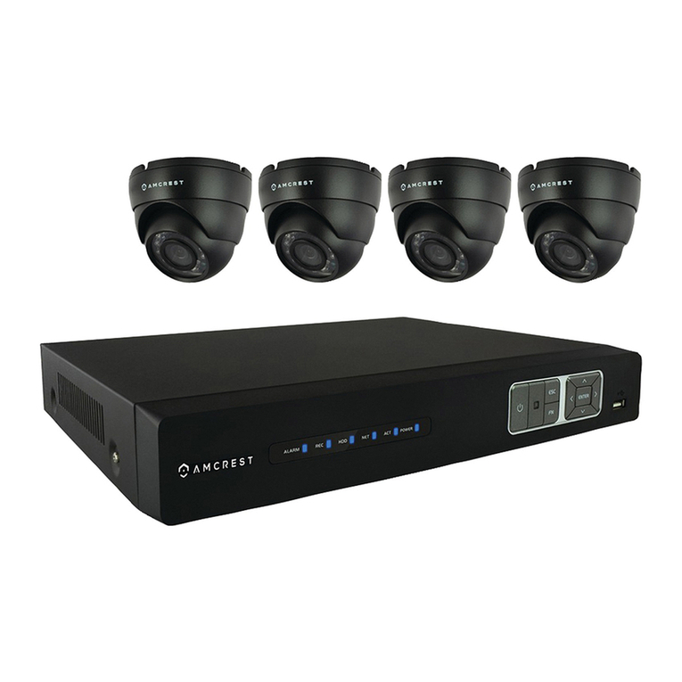
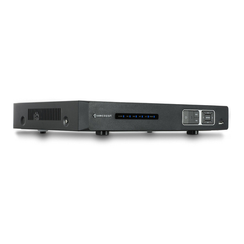
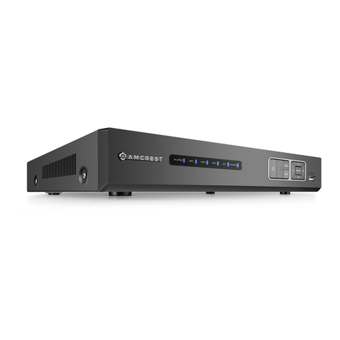
Amcrest AMDV960H4 User manual

AMDV960H4 User Manual
www.amcrest.com 1
AMDV960H4 User Manual
Version 1.2.1

AMDV960H4 User Manual
www.amcrest.com 2
TABLE OF CONTENTS
1PRODUCTION 4
1.1. Product Key Features 4
1.2. Front Panel Controls 5
1.3. USB Mouse 6
1.4. Soft Keyboard 7
1.5. Rear Panel Diagram 7
2GETTING STARTED 9
3LIVE VIEW 10
3.1. Understanding Live Preview Icons 10
3.2. Understanding Live Preview Toolbar 10
3.3. Understanding Home Menu 11
3.4. Using Digital Zoom 11
3.5. PTZ Control 12
3.5.1 PTZ Presets, Patrols & Patterns 12
3.5.2 PTZ Context Menu 12
4IP CHANNEL 14
5DISPLAY SETTINGS 15
5.1. Camera Settings 15
5.2. Displays Output Settings 16
6RECORD SETTINGS 17
6.1. Initializing Record Settings 17
6.2. Scheduling a Recording 18
7PLAYBACK AND BACKUP 20
7.1. Playback files from a video search 20
7.2. Understanding the Playback Interface 21
7.3. Backup the recorded file 22
8NETWORK SETTINGS 24
8.1 Configuring General Settings 24
8.2 Configuring Advanced Settings 25
8.2.1 DDNS 26
8.2.2 NTP 26
8.2.3 E-mail Settings 26

AMDV960H4 User Manual
www.amcrest.com 3
8.2.4 FTP Settings 27
8.2.4 IP Filter 28
9ALARM SETTINGS 29
9.1 Motion Detection 29
9.2 Detecting Video Loss 30
9.3 Detecting Exception 31
10 DEVICE MANAGEMENT 32
10.1 Managing HDDs 32
10.2 Configuring PTZ Settings 33
11 SYSTEM SETTINGS 34
11.1 General 34
11.2 User 35
11.2.1 Adding a New User 35
11.3 System Information 37
11.4 Maintenance 38
12 APP FOR PHONE AND TABLET 40
12.1 Configure the Amcrest Link 40
12.2 Live view in Amcrest Link 41
12.3 Playback in Amcrest Link 42
13 SMARTCLIENT/WEB FOR PC 44
13.1 Login Your Device 44
13.2 Live View 45
13.3 Playback 46
13.3.1 Remote playback and download 46
13.3.2 Playback Control 47
13.3 Local Settings 47
13.4 Device Settings 48

AMDV960H4 User Manual
www.amcrest.com 4
1 PRODUCTION
Thank you for your purchase of our Amcrest DVR. To get the most out of your device(s), please
read through this User Manual thoroughly. This user manual covers all the models of our DVR.
1.1.Product Key Features
Compression
Analog channels support PAL/NTSC video input, and the recording resolution supports up
to 960H
Digital channels support 1M, 1.3M, 2M pixels IP camera. Some models support up to 3M
pixel IP camera.
Video encoding parameters of each channel can be set separately, including frame rate and
bit rate.
Supports both composite stream and video only stream. Audio and video streams are strictly
simultaneous.
Monitoring
Supports VGA and HDMI video output. The display resolution supports up to 1080P.
Supports 1/4/8/9/16 screen live view.
Supports digital zoom on live view.
Supports privacy mask.
Supports PTZ preset and patrol.
HDD Management
Supports 1~8 internal SATA HDD(s) up to 3TB capacity.
Supports 1~2 external eSATA HDD(s) up to 3TB capacity.
Supports S.M.A.R.T. technology.
Use pre-allocating hard disk management technology and no disk fragments.
Recording and Playback
Supports cycle and non-cycle recording modes.
Supports manual, continuous, and motion recording.
Supports 8 recording time periods with separate recording types.

AMDV960H4 User Manual
www.amcrest.com 5
Supports Pre-record and Post-record.
Supports video data search and playback by channel number, recording type, time, and
event,
Supports pause, rewind, play fast, play slow, skip forward, and skip backward when in
playback, located in the progress bar.
Backup
Supports USB device and network remote backup.
Alarm and Exception
Supports various alarm inputs such as hard disk full, network break, IP conflict, and hard
disk error.
Supports various alarm responses such as camera recording, on screen warning, audible
warning, send email, etc.
Network
Supports 10/100 adaptive network interface.
Supports TCP/IP protocols, PPPoE, DHCP, DNS, DDNS, NTP, UPnP, ONVIF, RTSP etc.
Supports remote search, playback, and download video files.
Supports remote configuration.
Supports remote image capturing.
Supports remote PTZ control.
Others
Supports front panel, mouse, IR control operation.
Supports multi-level user management; each user can have individual DVR access rights.
Powerful DVR log, including operation, alarm, information, and exception log.
1.2.Front Panel Controls
AMDV960H4 User Manual
www.amcrest.com 6
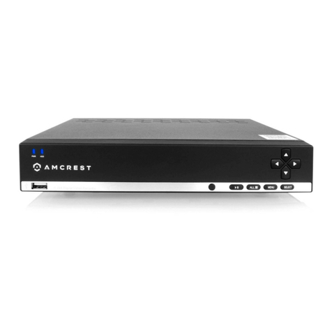
The controls on the front panel include:
1. USB Ports: Universal Serial Bus (USB) ports for additional devices such as a USB mouse
and USB Hard Disk Drive (HDD).
2. POWER: POWER indicator lights on when DVR is powered on.
3. HDD: HDD indicator lights up when the hard drive is active and, flashes rapidly when
recording.
4. IR Receiver: Receiver for IR remote.
5. Function button:
a) Play / pause button is used for playback control
b) ALL button is used to live-view all the channels
c) Menu button is used to pop-up the main menu
d) Select button is used to confirm selection in any of the menu modes
6. Direction button: DIRECTION buttons are used to navigate between different fields and
items in menus. In Preview mode, these buttons can be used to cycle through channels.
1.3.USB Mouse
A regular 3-button (Left/Right/Scroll-wheel) USB mouse can also be used with this DVR. The
buttons on the mouse correspond to:
1. Left Button:
Single-Click: Select a component of a menu, such as a button or an input field.
Double-Click: Switch between single screen and multi-screen mode in Preview/
Playback mode.
Click and Drag: Clicking and dragging the Left mouse button can be used to control the
digital zoom area. It can also be used to change the live view channel sequence or
setup the alarm areas.
2. Right Button:
Single-Click: Shows pop-up menu or exit current UI page.
3. Scroll-wheel:
This is used to change the selected item for list control.

AMDV960H4 User Manual
www.amcrest.com 7
1.4.Soft Keyboard
When a mouse is used to perform task on the DVR, clicking on a text input field will bring up the
Soft Keyboard.
The buttons on the soft keyboard represents:
Lowercase: Designates lowercase input is being used.
Uppercase: Designates uppercase input is being used.
Backspace: Delete the character in front of the cursor.
Space: Input spaces between letters.
Enter: Confirm selection.
ESC: Exit out of Soft Keyboard.
1.5.Rear Panel Diagram
No
Item
Description
1
AUDIO IN
RCA connectors for analog audio input.
2
VIDEO IN
BNC connector for analog video input.
3
AUDIO OUT
RCA connectors for analog audio output.
4
VGA
DB9 connector for VGA output. Display local video output and menu.
5
eSATA
eSATA port, connect eSATA HDD for recording or backup
6
HDMI
HDMI output, Display local video/Audio output and menu.
7
LAN
Connector for LAN (Local Area Network).
8
USB
Connector for USB device.
9
PTZ
PTZ control port (Some models don’t support this feature)- RS485.

AMDV960H4 User Manual
www.amcrest.com 8
10
DC POWER IN
12V DC power input.

AMDV960H4 User Manual
www.amcrest.com 9
2 GETTING STARTED
2.1 Starting and Shutting Down Your DVR
Proper startup and shutdown procedures are crucial to extending the life of your DVR. To startup
your DVR, please plug the power supply into an electrical outlet. It is HIGHLY recommended that
an Uninterruptible Power Supply (UPS) be used in conjunction with the unit. The Power indicator
LED on the front panel should turn on, indicating the unit is receiving power.
To shutdown the DVR:
1. Enter the Shutdown menu, click on Menu > Shutdown.
2. Select the Shutdown button.
3. Click the OK button.
4. Unplug the power supply on the rear panel to safely shutting down the system.
2.2 Rebooting and Locking Your DVR
In the Shutdown menu, you may also reboot or lock your DVR. Locking your DVR will return you
to the Live Preview mode. The username and password must be re-entered to access the menus
again. The Reboot button will reboot your DVR. To reboot or lock your DVR:
1. Enter the Shutdown menu by clicking Menu > Shutdown.
2. Select the Lock button to lock the DVR or the Reboot button to reboot the DVR.

AMDV960H4 User Manual
www.amcrest.com 10
3 LIVE VIEW
The Live Preview mode is automatically started after the DVR boots up. It is also at the very top
of the menu hierarchy, thus hitting the ESC multiple times (depending on which menu you’re on)
will bring you to the Live Preview mode.
3.1.Understanding Live Preview Icons
There are multiple icons on each display in Live Preview mode to indicate different camera
status. These icons include:
Motion Detection Icon: Indicates motion detection.
IP Channel Icon: Indicates this is an IP channel. It could be 720P, 960P, 1080P.
Record Icon: Indicates the current channel is recording.
Audio Icon: Indicates the current channel is outputting audio.
Video Disable Icon: Indicate the preview of this channel is disabled.
3.2.Understanding Live Preview Toolbar
Click any channel in live view mode and a toolbar will be pop up:
1. Playback: click this icon to enter the playback menu;
2. Audio: mute/unmute this channel;
3. PTZ: control the PTZ of this channel

AMDV960H4 User Manual
www.amcrest.com 11
4. Digital Zoom
5. Image parameter control: change the parameters of this camera
6. Channel configuration
7. Exit toolbar
3.3.Understanding Home Menu
Click the right-button of the mouse and the home menu will be pop up:
1. Home Icon: enter the main menu;
2. Single channel live view;
3. Four channels live view;
4. Eight channels live view;
5. Nine channels live view;
6. Next group live view;
7. Picture in picture mode;
8. Manual record;
9. Setup wizard;
3.4.Using Digital Zoom
To use digital Zoom in Live Preview mode:
1. Click one channel on live view, the toolbar will be pop up;
2. Select Digital Zoom, enter digital zoom mode:
: To enlarge the picture 2 times for each click. 6 times at most;
: To shrink the enlarged picture until normal size;
: To enlarge the selected area to full screen;
: To turn the picture into normal size;
: Exit.

AMDV960H4 User Manual
www.amcrest.com 12
3.5.PTZ Control
Clicking the PTZ icon on the live-view toolbar will bring up the PTZ control panel.
3.5.1 PTZ Presets, Patrols & Patterns
The controls on the PTZ panel include:
1. Directional Pad/Auto-scan Buttons: Controls the movements and directions of the PTZ.
Center button is also used to start auto-scan of PTZ.
2. Speed: Adjusts the movement speed of the PTZ.
3. Zoom: Used to zoom in and out with the PTZ.
4. Focus: Used to adjust the focus of the PTZ.
5. Iris: Used to open up or close the iris of the camera.
6. Preset: A Preset is a position that the camera is in which is saved to memory to be retrieved
later. Choose this button to enter preset configuration menu.
7. Patrol: Initiates patrol mode. You’ll need to define a series of Preset points for the camera to
patrol between. Choose this button to enter patrol configuration menu.
8. Exit: Closes the PTZ controls.
3.5.2 PTZ Context Menu

AMDV960H4 User Manual
www.amcrest.com 13
1. Camera No: Switch quickly between cameras.
2. Call Preset: Returns the camera to a Preset point.
3. Call Patrol: Initiates a patrol of your choice.
4. Preset: Defines a Preset point.
5. Patrol: Initiates or stops a patrol.
6. PTZ Menu: Toggles the appearance of the PTZ Control Menu onscreen. While the PTZ
Control Menu is hidden, the DVR will still be in PTZ mode. The context menu can still be
opened via right-clicking the interface.
7. PTZ Settings: Opens the PTZ Settings menu where you can adjust the control method for
the camera.

AMDV960H4 User Manual
www.amcrest.com 14
4 IP Channel
The IP Channel menu enables you to view specific information about cameras that are currently
connected to your DVR such as channel number, IP address, and status.
Auto-adding: If you check this, your DVR will automatically display video from cameras it has
detected in your local area network. This option is disabled by default, so you have to manually
add the IP cameras to your DVR.
IP Camera list: In this list, all the IP cameras in your local area network will be listed
automatically after you click the button of Scan.
To add an IP camera to your DVR, please select an available channel to which you
want to assign a camera from the channel drop-down list, and then input the user name
and password. Also you can manually add an IP camera by inputting the IP
address/port or RTSP URL, user name, and password into the list. When you’re
finished, click the Apply button to save the new configuration.
To delete an IP camera from your DVR, please select that IP camera and select None
from the channel drop-down list. When you’re finished, click the Apply button to save
the new configuration.
Detail: If one IP camera is connected with your DVR, you can click this button to show this IP
camera’s status:
Scan: Click this button and all the IP cameras in your local area network will be listed.

AMDV960H4 User Manual
www.amcrest.com 15
5 DISPLAY SETTINGS
5.1.Camera Settings
Camera menu is where you can make adjustments to how the DVR displays the feed coming
from your cameras. You can adjust aspects of each channel/camera, including:
Camera No.: Choose the camera / channel you want to edit here. The Camera No. is the
same as the number written on the rear panel next to the BNC socket used to connect the
camera.
Camera Name: Select a name for the camera you’ve selected. By default, all channels are
named the same as the Camera No. field, but this can be set to anything you’d like up to 16
characters.
Disable Preview: When checked, the live view of the channel you’ve selected will be
disabled.
Display Camera Name: When checked, the name you’ve selected for the camera/channel
will be displayed on-screen as an overlay.
Record Date: When checked, the date (as displayed) will be recorded directly on your
videos. This can be useful, as it creates an inseparable record of exactly when the footage
was captured.
OSD Display Position: Gives you access to a screen where you can easily set the exact
positions of any overlayed text, such as the camera name and the date and time. You can
simply select any item you want to move (such as the Channel Name and/or the Date and
Time) and click and drag it to the position you’d like it to be. To exit the OSD Display Position
screen, press the right click button. A context menu will appear with two options: Save and
Exit. To exit without saving, simply choose Exit. If you want to save your changes, choose
Save first.

AMDV960H4 User Manual
www.amcrest.com 16
Image Settings: Gives you access to change camera image, including brightness, contrast,
saturation, and hue
Mask: When checked, this allows you to create, place, and shape a “privacy mask” which
obscures part of the image on the associated channel.
5.2.Displays Output Settings
Live Preview allows you to customize your display to your own needs.
The settings available in this menu include:
Display resolution
Transparency: To adjust the menu transparency.
Mouse Sensitivity
Border Adjustment: To adjust the border of video output.
Audio: Enables/disable audio output for the selected video output.

AMDV960H4 User Manual
www.amcrest.com 17
6 RECORD SETTINGS
There are multiple ways to setup your DVR for recording. They include setting up a recording
schedule, triggering recording by motion detection, and manually starting the recording.
6.1.Initializing Record Settings
Before setting your DVR up for recording, certain settings should be configured first. The steps to
configuring these settings are:
1. You should initialize the HDD through HDD management before proceeding.
2. Navigate to Main Menu > Recording. You will be taken to the Recording Settings menu.
3. Select the camera you would to configure the settings for.
4. Configure settings for:
Encoding Parameters: Select main stream or sub stream.
Record Audio: Select to record the audio of the camera.
Resolution.
Frame Rate: Select recordings frame rate.
BitRate Type: Select either Variable or Invariable bit rate.

AMDV960H4 User Manual
www.amcrest.com 18
Set additional recording settings:
Overwrite: Set to overwrite the HDD to continue recording when it is full.
Pre-record: Set to pre-record before the actual recording begins.
Post-record: Sets the time to post-record after the actual recording ended.
Pack Duration: Sets the time for how long the DVR will be recording before splitting the
output file.
6.2.Scheduling a Recording
Scheduling a recording allows you to setup the DVR to only record when you want it to.
To setup a recording schedule:
1. Enter the Record Settings menu (Main Menu > Recording > Schedule).

AMDV960H4 User Manual
www.amcrest.com 19
2. Select the Camera to edit schedule for.
3. Check Enable Schedule.
4. Select recording Type. Recording type can be based on time and triggered by a schedule,
motion detection, motion or alarm, and alarm. Motion detected and alarm triggered
recordings are further explained in Configuring Alarms.
5. Repeat the steps for other cameras or copy settings from one channel to others by Copy To.
6. Click OK to finish and save the schedule settings.

AMDV960H4 User Manual
www.amcrest.com 20
7 PLAYBACK AND BACKUP
7.1.Playback files from a video search
To initiate playback:
1. Select the channel you’d like to playback.
2. From the Video Type menu, select the type of video you’d like to playback. The options are
Manual, Schedule, Motion, and All.
3. Set your Start Date/Time and your End Date/Time. If you want to see a graphical
representation of when recordings were made and what recording mode triggered them,
Table of contents
Other Amcrest DVR manuals

Amcrest
Amcrest 960H User manual

Amcrest
Amcrest AMDVTENL8 User manual

Amcrest
Amcrest HDCVI User manual

Amcrest
Amcrest NV42 EI Series User manual

Amcrest
Amcrest H5 Series User manual

Amcrest
Amcrest AMDV5M8 User manual

Amcrest
Amcrest AMDV10808-8B User manual

Amcrest
Amcrest AMDV5M32-6TB User manual

Amcrest
Amcrest General 720P(V2) Mini 1U Series User manual

Amcrest
Amcrest NVR11H Series User manual