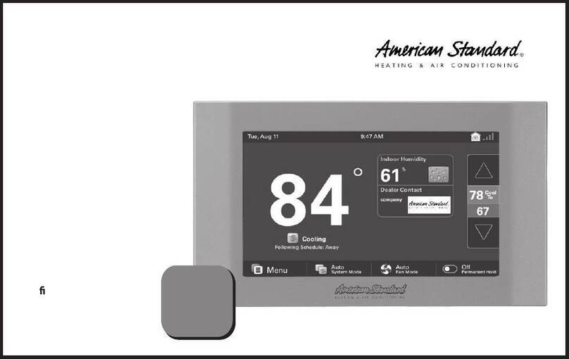
American Standard AccuLink Platinum 1040 Operation manual

AccuLink™ Platinum 1040
AZON1040 Zone Sensor
Installation & User Guide
The 1040 is an easy to use communicating zone sensor with a color touch screen.
This guide will help you install and congure your AZON1040 zone sensor quickly and easily.
11-HD22D1-1D-EN

page 1AZON1040 Installation and User Guide
AccuLink AZON1040
Welcome!
Communicating Zone Sensor with touch screen interface
This guide will introduce you to the 1040’s many features and get you
started using your Zone Sensor.
The intuitive interface and powerful features incorporated into the
compact design of the color touch screen zone sensor represent the
ultimate in climate control and comfort technology from the industry’s
leader in residential HVAC systems.
CONTENTS
Welcome . . . . . . . . . . . . . . 1
User Guide . . . . . . . . . . . . . 2
Touch Screen . . . . . . . . . . . 2
Home Screen . . . . . . . . . . . 3
Menu Screen . . . . . . . . . . . 5
Name Sensor Screen. . . . . . . . 6
Brightness . . . . . . . . . . . . 7
Backlight . . . . . . . . . . . . . 8
Screen Saver . . . . . . . . . . . 9
Color Themes . . . . . . . . . . 10
Calibration . . . . . . . . . . . 11
Clean Screen . . . . . . . . . . 12
Reboot . . . . . . . . . . . . . 12
Installation . . . . . . . . . . . . 13
Safety . . . . . . . . . . . . . . 13
General Information . . . . . . . 14
Location . . . . . . . . . . . . 15
Mounting . . . . . . . . . . . . 17
Wiring. . . . . . . . . . . . . . 18
Zone Assignment . . . . . . . . 20
Power-Up Sequence . . . . . . . 21 NOTE: 1050 software version 5.7 or later is required.

page 2
11-HD22D1-1D-EN
User Guide
CAUTION:
Do not use hard
or sharp objects
to touch the
screen.
The 1040 utilizes a resistive touch screen, which allows you
to apply light pressure with your nger or any non-sharp
object in order to interact with the device.
Touch Screen

page 3AZON1040 Installation and User Guide
User Guide
Home Screen
Current Indoor
Humidity
Heating
or Cooling
temperature
adjustment
Current
temperature
and status
Current Outdoor
Temperature
Menu Screen
Day/Date*
* Day/Date/Time set on 1050 control
Time*
Fan Mode (Auto/On)
View and adjust
other zone
settings
Permanent hold
temperature setting
Notication and System Alerts
Increase
temperature
Decrease
temperature

page 4
11-HD22D1-1D-EN
User Guide
F n Mode
Back
Auto On
F n will run when the system runs
On
Perm nent Hold
Holding Perm nently
He t
to
62
72
6:30 PMSat, Aug 9
62
Cool
to
72
Menu Off
Permanent Hold
Following Schedule
Fan Running
Screen Off
Indoor Humidity
%
32
75
Fan Mode
On
OutdoorTemp
94
Upstairs
Heating & Cooling
Setpoints:
- Select a setpoint
to modify
- Use the arrows
to increase or
decrease the
highlighted
setpoint
Home Screen
Select the Permanent Hold
button to toggle between On/O
options.
The 1040 System Mode is
bound to the 1050 System
Mode and cannot be modied
from the 1040 zone sensor.
The Fan Mode button allows you to
choose between Auto or On fan modes.
* Auto Fan Mode turns the fan
o and on with the heating and
cooling system operation.
*
On Fan Mode
runs the fan
continuously. If enabled, the
Smart Continuous Fan feature may
disable fan operation when the
indoor humidity level rises above
the humidity setpoint.
* ON: maintains current temperature setpoint until you manually
change the setpoint.
* OFF: resumes scheduling if enabled. A zone schedule may
be created or modied from the 1050 control’s Schedules &
Presets screen.

page 5AZON1040 Installation and User Guide
User Guide
page 5
Menu
Back
Ren me
Sensor C libr tionDis/l y RebootCle n Screen
About
Rename
sensor Reboot the
zone sensor
Model and serial number, software version,
other zone sensor information.
Clean screen function
Return to the
Home Screen
Menu Screen
Display features (Brightness/
Backlight/Screen Saver/
Color Themes)
Calibration osets (Indoor
Temperature/ Indoor
Humidity)

page 6
11-HD22D1-1D-EN
User Guide
page 6
Name Sensor Screen
This screen allows you to assign
a unique name to the 1040 zone
sensor.
On rst boot-up this screen will
appear to allow you to set a name
for the 1040 zone sensor.
The sensor name may include up
to 20 characters. Select Done to
apply the changes.
Navigate to Name Sensor Screen by selecting:
Home Screen > Menu > Rename Sensor

page 7AZON1040 Installation and User Guide
User Guide
Screen Settings
C ncelApply
Screen Settings
Select a tab to
view dierent
screen setting
options
Adjust the
screen active
and standby
brightness
Navigate to Screen Settings by selecting: Home Screen >
Menu > Screen Settings > Brightness
Brightness
Apply changes Return to the Menu without saving

page 8
11-HD22D1-1D-EN
User Guide
Return to the Menu without saving
Screen Settings
C ncelApply
Adjust how
long the screen
will remain
active after
the last screen
touch
Backlight
Apply changes
Navigate to Screen Settings by selecting: Home Screen
> Menu > Screen Settings > Backlight

page 9AZON1040 Installation and User Guide
User Guide
Screen Settings
C ncelApply
Select the
screen saver
you would
like displayed
during standby
mode
Adjust how long the zone sensor will wait to display screen saver
Screen Saver
Return to the Menu without savingApply changes
Navigate to Screen Settings by selecting: Home Screen
> Menu > Screen Settings > Screen Saver

page 10
11-HD22D1-1D-EN
User Guide
C ncelApply
Screen Settings
Select a custom
color theme for
the zone sensor
Color Themes
Return to the Menu without savingApply changes
Navigate to Screen Settings by selecting: Home Screen
> Menu > Screen Settings > Color Themes

page 11 AZON1040 Installation and User Guide
User Guide
Calibration
Adjust the Indoor Temp and Humidity values
Return to the Menu
Navigate to the Calibration screen by selecting:
Home Screen > Menu > Calibration

page 12
11-HD22D1-1D-EN
User Guide
The Clean Screen feature temporarily locks the screen
for 30 seconds to allow the display to be cleaned.
From the Reboot screen, you can reboot the zone
sensor with the push of a button. When you select this
option you will be prompted to ensure you would like
to reboot your zone sensor.
NOTE: The HVAC system will not stop operation while
the zone sensor reboots.
Clean Screen Reboot
Navigate to Clean Screen by selecting: Home Screen
> Menu > Clean Screen
Navigate to the Reboot screen by selecting: Home
Screen > Menu > Reboot

page 13 AZON1040 Installation and User Guidepage 13
Installation
NOTE: Use 18-gauge color-coded
thermostat cable for proper wiring.
Shielded cable is not typically
required. Keep this wiring at least
one foot away from large inductive
loads such as electronic air cleaners,
motors, line starters, lighting
ballasts and large distribution
panels.
Failure to follow these wiring
practices may introduce electrical
interference (noise) which can
cause erratic system operation.
All unused thermostat wire to be
grounded at indoor unit chassis
ground only. Shielded cable may
be required if the above wiring
guidelines cannot be met. Ground
only one end of the shield to the
system chassis.
This information is intended for
use by individuals possessing
adequate backgrounds of electrical
and mechanical experience. Any
attempt to repair a central air
conditioning product may result
in personal injury and/or property
damage. The manufacturer or
seller cannot be responsible for the
interpretation of this information,
nor can it assume any liability in
connection with its use.
LIVE ELECTRICAL COMPONENTS!
During installation, testing,
servicing, and troubleshooting of
this product, it may be necessary
to work with live electrical
components. Failure to follow
all electrical safety precautions
when exposed to live electrical
components could result in death
or serious injury.
Safety
⚠WARNING ⚠ ⚠ WARNING ⚠

page 14
11-HD22D1-1D-EN page 14
Installation
Box Contents
— 1 Control
— 1 Sub-base
— 2 #6 18x1 Phillips slotted head mounting screws
— 2 #6x1 Nylon Drywall Anchors
— 1 Installation and User Guide
— 1 USB “On-the Go”Adapter Cable
(Micro USB plug to Standard USB receptacle)
The 1040 Connected Zone Sensor has a 4.3” color
touch screen and oers a full-featured and easy-to-
use interface.
General Information

page 15 AZON1040 Installation and User Guidepage 15
Installation
Location
The 1040 is designed for installation in climate
controlled living spaces when applied with American
Standard’s’s AccuLink™zone control system. Place the
zone sensor in a central location with good circulation.
For proper temperature sensing, avoid exposing the
1040 to heat radiated from lamps, sun light, replaces
or any other radiant heat source.
Avoid locations close to windows, behind doors or
alcoves with poor air circulation, adjoining outside
walls, or doors that lead to the outside.
Select a location that prevents the 1040 from being
directly exposed to air currents from supply registers or
ceiling fans. Installation Figure 1
Natural heat dissipation
from the Touch Screen
Onboard
Thermistor
Sensor
5 FEET
2 FEET
Zone
Floor
Vent
Window
Celing
Optimum
Correct
Placement
Zone
Sensor

page 16
11-HD22D1-1D-EN page 16
Installation
Location
Mount the zone sensor on a section of interior wall that
does not contain hot or cold water pipes or duct work.
IMPORTANT: The 1040 zone sensor utilizes a 4.3” color
touch screen. This screen generates heat which is
vented out the top of the zone sensor utilizing natural
convection. If an air source is directed at or from above,
heat from the screen can be trapped within the zone
sensor and may cause the indoor temperature to be
biased. (Installation Figure 1 & 2)
Installation Figure 2
Problematic Air Patterns Incorrect
Placement
Locate the zone sensor in an area
with minimal airow patterns thereby
avoiding interruption of natural heat
dissapation.

page 17 AZON1040 Installation and User Guidepage 17
Installation
Mounting
1. Turn OFF all power to heating and cooling
equipment.
2. If an existing zone sensor is being replaced:
a. Remove the existing zone sensor from the wall.
b. Disconnect the wires from the existing zone
sensor being careful not to allow them to fall
back into the wall.
3. Carefully pry the sub-base away from the 1040
using a small at-blade screwdriver. Note that the
tight t is normal and ensures that the sensor is held
securely to the sub-base when mounted on the wall.
4. Route the wires through the opening on the sub-
base.
B/CRDODT
RS1
Thermostat
Wires
RJ-45
Plug
Mounting Holes Optional Mounting Hole
Installation Figure 3
NOTE: RS1 and ODT terminals are disabled. They
are not compatible with the 1040 zone sensor.
NOTE: RJ-45 plug is disabled. It is not compatible
with the 1040 zone sensor.

page 18
11-HD22D1-1D-EN page 18
Installation
Mounting Wiring
5. Drill the holes in the wall where marked.
6. Mount the sub-base to the wall using included
mounting screws and drywall anchors. Make sure
all wires extend through the hole in the sub-base
(Installation Figure 4).
Installation Figure 4
Wall
If a more secure
mounting is
needed an optional
mounting hole is
available.
1. Adjust the length and position of each wire to
reach the proper terminal on the connector block
of the sub-base. Strip 1/4” of insulation from
each wire. Do not allow adjacent wires to short
together when connected.
2. Match and connect zone sensor wires to the
proper terminals on the connector block. Refer to
Field Wiring Diagrams included in the Zone Panel
document.
3. Push excess wire back into the wall and seal the
hole to prevent air leaks.
NOTE: Air Leaks coming through the wiring hole may
bias the ability of the zone sensor to accurately
measure and display the zone temperature.
4. Attach the 1040 zone sensor to the sub-base.
5. Turn ON power to the heating and cooling
equipment.

page 19 AZON1040 Installation and User Guidepage 19
Installation
Zone Assignment
This is the Indoor Sensor Setup screen on the 1050
control. When setting up zoning it will ask you if you
have zone sensors to assign and take you to this menu.
When the 1040 is powered and wired into the zone
system you should see it in the list of available sensors.
Navigate to the selected zone on the top left, then
select the 1040 on the right column and select Assign.
Once assigned, the sensor will move over to the left
column and average with the other sensors assigned in
that zone. You can assign up to 4 sensors per zone.
NOTE: 1050 software version 5.7 or later is required.
Features may dier depending on software version.
Refresh Assign
Done Wireless
Sensor
Upstairs Gr at Room-01
1040
14ACD - Onlin
Zon and Assign d S nsors Availabl S nsors
W ightMod l / S rial NoS nsor Nam
1Comfortlink II 1050 100%
Onboard S nsor
Downst...
Navigate to Indoor Sensor Setup on the 1050 control
from the Service Menu.
This manual suits for next models
1
Table of contents
Other American Standard Control System manuals